


 Loading...
INSTALLATION AND
OPERATION MANUAL
Microprocessor controller for fan coils
ECFWEB6
ECFWER6
ECFWDER6
1 |
2 |
3 |
4 |
5 |
6 |
7 |
8 |
9 |
1 |
|
|
|
|
|
|
|
|
2 |
|
|
|
|
|
|
3 |
|
|
|
5 |
||
|
|
|
|
|
|
|
|
|
|
22.5°C |
|||
|
|
|
|
|
|
1 |
|
16.5°C |
|
|
28.5°C |
||
|
|
|
|
|
|||||||||
|
|
|
|
|
|
2 |
|
|
|
||||
|
|
|
|
|
|
|
|
|
|
||||
|
|
|
|
|
|
|
|
|
|||||
|
|
|
|
3 |
|
|
|
|
|
|
|
||
|
|
4 |
|
3 |
|
|
|
|
|
||||
|
|
|
|
|
|
||||||||
|
|
|
|
|
|
|
4 |
1 |
2 |
2 |
|
||
|
|
|
|
|
|
|
|
|
|||||
|
|
|
|
|
5 |
|
|
|
|
|
|
|
|
|
|
|
|
|
|
|
|
|
|
|
|
||
|
|
|
|
|
|
|
|
|
|
|
|
||
|
|
|
|
|
|
|
|
||||||
|
|
|
|
|
|
|
|
|
|
|
|
|
|
2 |
|
4 |
5 |
|
|
7 |
8 |
|
|
|
105 |
|
|
|
7 |
|
|
|
0 |
|
2 |
|
90 |
|
|
|
|
|
1 |
|
|
6 |
|
7 |
8 |
86 |
10 |
11 |
12 |
|
|
|
9.319
7 |
|
2 |
|
24 |
2 |
|
|
|
|
|
1 |
130 |
|
1 |
93 |
|
2 x (ø5x8) |
17.7 |
7 |
|
9 |
|
10 |
|
11 |
|
12 |

13 |
|
16 |
|
17 |
|
19
20
14 |
|
17 |
|
18 |
|
15 |
|
18 |
|
20 |
21
4
2
21
ECFWEB6 |
Microprocessor controller |
|
ECFWER6 |
||
for fan coils |
||
ECFWDER6 |
||
|
Installation and operation manual
TABLE OF CONTENTS |
Page |
Main features ................................................................. |
1 |
Main functions and equipment....................................... |
1 |
Packing list.............................................................. |
2 |
If options need to be installed, always refer to the relevant manual of the option for additional information.
Control panel .......................................................... |
2 |
MAIN FEATURES |
|
Temperature range |
2 |
||
|
LED indicators ........................................................ |
2 |
Description of the operating modes........................ |
3 |
Technical data and operation limits ........................ |
5 |
Possible configurations .................................................. |
7 |
Before installation .......................................................... |
9 |
ECFWEB6 installation instructions ................................ |
9 |
Installation on the support and on the fan coil ........ |
9 |
ECFWER6 + ECFWDER6 installation instructions...... |
10 |
Installation ............................................................ |
10 |
Setting the microswitches ............................................ |
10 |
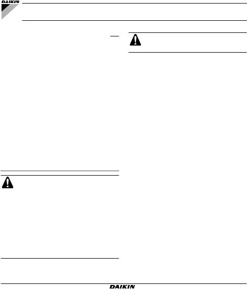
Installing the air and water temperature probes........... |
11 |
Position of the air temperature probe ................... |
11 |
Position of the water temperature probe............... |
11 |
Installing the power contactor ...................................... |
12 |
This controller is designed to control Daikin fan coil units.
■ ECFWEB6 |
Built-in for FWV and FWL |
■ ECFWER6 |
Remote for FWV, FWL and FWM |
■ ECFWDER6 |
Remote for FWD |
MAIN FUNCTIONS AND EQUIPMENT
■Regulation of the air temperature via automatic variation of the fan speed.
■Regulation of the air temperature via ON/OFF switch of the fan at a fixed speed.
■Time function (only for ECFWEB6).
■Regulation of the air temperature via control of ON/OFF valves (on 2-pipe or 4-pipe systems).
Wiring diagrams........................................................... |
12 |
Wiring parts table ................................................. |
12 |
Read this manual attentively before starting up the unit. Do not throw it away. Keep it in your files for future reference.
Improper installation or attachment of equipment or accessories could result in electric chock, short-circuit, leaks, fire or other damage to the equipment. Be sure only to use accessories made by Daikin which are specifically designed for the use with the equipment and have them installed by a professional.
If unsure of installation procedures or use, always contact your Daikin dealer for advice and information.
■Control of the electric heater as integration or replacement of a heating circuit with delayed fan stopping.
■Cooling/Heating switching mode in following way:
■Manual — on the controller
■Manual — on the remote switch
■Automatic — based on the water temperature
■Automatic — based on the air temperature
■The controller is also equipped with:
■Free contacts for external enabling signal (i.e.: reed contact, remote ON/OFF switch, proximity contact etc.) that may enable or disable the unit. (Closed contact = OFF; open contact= ON)
■Free contacts for the centralized cooling/heating switching system. (Closed contact = cooling, open contact = heating)
■Water temperature probe (white)
■Air temperature probe (black)
Installation and operation manual |
|
ECFWEB6+ECFWER6+ECFWDER6 |
1 |
4PW17551-1 |
Microprocessor controller for fan coils |
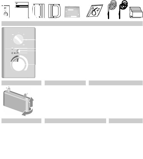
Packing list (See figure 1)
|
Part |
ECFWEB6 |
ECFWER6 ECFWDER6 |
|
1 |
Controller |
1 |
1 |
1 |
|
|
|
|
|
2 |
Manual |
1 |
1 |
1 |
|
|
|
|
|
3 |
Cover plate left |
1 |
0 |
0 |
|
|
|
|
|
4 |
Cover plate right |
1 |
0 |
0 |
|
|
|
|
|
5 |
Support |
1 |
0 |
0 |
|
|
|
|
|
6 |
Accessory bag |
|
|
|
|
• wire clamp |
1 |
1 |
1 |
|
• 2 screws |
|||
|
|
|
|
|
|
• probe holder |
|
|
|
|
|
|
|
|
7 |
Water probe |
1 |
1 |
1 |
|
|
|
|
|
8 |
Air probe |
1 |
integrated in controller |
|
|
|
|
|
|
9 |
Power interface |
0 |
0 |
1 |
|
|
|
|
|
Control panel
Refer to figure 2 to catch the look of the controller.
1Operation mode selector, to turn the fan coil on and off, to choose the type of operating mode (automatic or at fixed speed) and to control the electric heating.
2Operation LED indicating that cooling operation mode is active (blue).
3Cooling/Heating selector.
4Operation LED indicating that heating operation mode is active (red).
5Thermostat to control the room temperature.
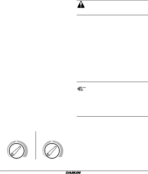
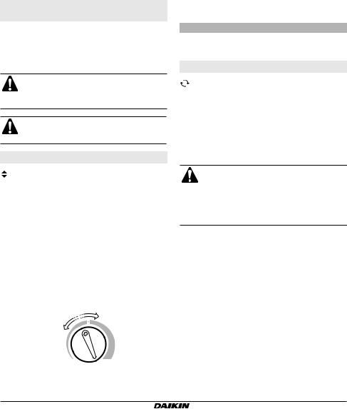
Temperature range
The print around the selector switch of the thermostat represents temperature ranges from minimum, over comfort, to maximum. The ranges refer to different temperatures, depending on the selected operating mode as illustrated in the figure below.
Cooling mode |
|
Heating mode |
25°C |
|
20°C |
19°C |
31°C 14°C |
26°C |
When automatic cooling/heating switching mode based on the air temperature is running, the temperature of the thermostat is as illustrated in figure 3.
LED indicators
The various combinations in which the LED lights up indicate procedures and operating status of the controller.
■Blue LED lit indicates that the cooling mode is running. The unit is running or waiting for an input from the thermostat.
■Red LED lit indicates that the heating mode is running. The unit is running or waiting for an input from the thermostat.
■Blue and red LEDs lit indicates that the unit did not receive an enabling signal. The water temperature does not enable the air cooling or heating functions (see "Automatic cooling/heating switching mode based on the water temperature" on page 3) or the temperature of the air is within the neutral zone (see "Automatic cooling/heating switching mode based on the air temperature" on page 4).
NOTE To determine which operating mode is
selected when an enabling signal is missing (blue and red LEDs are both lit), turn the knob of the thermostat until one of the two LEDs starts to flash and then remains lit. This LED points out the selected operating mode. Once the operating mode has been established, turn the thermostat back to the desired position.
■Double flashing of the blue LED means that the thermostat has sent an input to the unit for starting cooling mode. It flashes when the room temperature and the set cooling temperature are the same.
■Double flashing of the red LED means that the thermostat has sent an input to the unit for starting heating mode. It flashes when the room temperature and the set heating temperature are the same.
The temperature of the air in the room can be seen at any time on the thermostat range turning the knob of the thermostat.
ECFWEB6+ECFWER6+ECFWDER6 |
|
Installation and operation manual |
Microprocessor controller for fan coils |
4PW17551-1 |
2 |
Description of the operating modes
Room thermostat with air temperature control
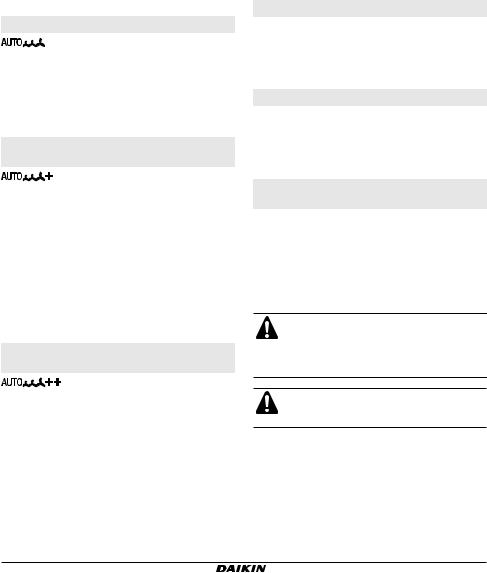
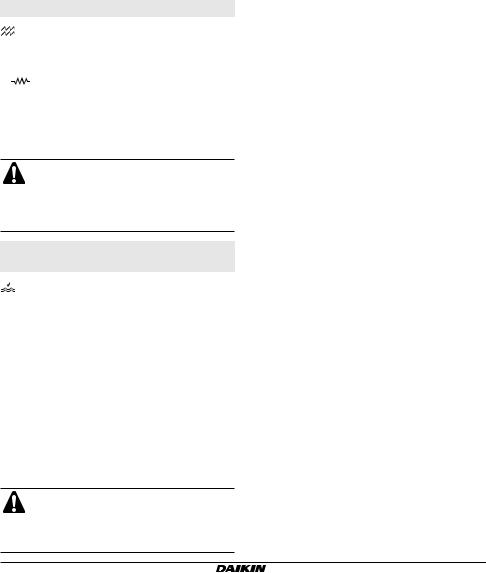
With the speed selector switch turned to 
 , the fan speed is switched automatically based on the difference between the temperature set on the thermostat and the room temperature.
With the selector switch turned to  ,
,  , or
, or  the ventilation mode is of the ON/OFF type.
Room thermostat with ON/OFF valve control for 2-pipe systems
With the speed selector switch turned to 
 , the fan speed is switched automatically based on the difference between the temperature set on the thermostat and the room temperature.
With the selector switch turned to  ,
,  , or
, or  the ventilation mode is of the ON/OFF type.
The water valve is shut off once the desired temperature is reached
In cooling mode the fan continues at minimum speed, even after the valve of the cooling circuit has shut off.
In heating mode the fan is stopped as soon as the valve of the heating circuit is shut off.
Room thermostat with ON/OFF valve control for 4-pipe systems
With the speed selector switch turned to 
 , the fan speed is switched automatically based on the difference between the temperature set on the thermostat and the room temperature.
With the selector switch turned to  ,
,  , or
, or  the ventilation mode is of the ON/OFF type.
The water valve is shut off once the desired temperature is reached
In cooling mode the fan continues at minimum speed even after the valve of the cooling circuit has shut off.
In heating mode the fan is stopped as soon the valve of the heating circuit is shut off.
Manual built-in cooling/heating switching mode

 M
M
The controller is pre-arranged to operate manually in the desired mode. It is enabled by pressing the selector key. The blue (cooling) and red (heating) LEDs point out the selected operating mode.
Manual remote cooling/heating switching mode

 MD
MD
The controller is pre-arranged to operate manually and remotely in the desired mode. This mode is carried out by connecting the system to a remote switch. Use the special terminals on the electronic PCB of the controller.
Automatic cooling/heating switching mode based on the water temperature

 H2O
H2O
The controller automatically selects the cooling or heating mode based on the temperature of the water and according to the following logic:
Water temperature <17°C — cooling mode is set Water temperature >37°C — heating mode is set Water temperature between 17°C and 37°C — the system is disabled
For switching based on water temperature, the supplied water probe needs to be installed.
See chapter "Position of the water temperature probe" on page 11 for installation of the water temperature probe.
In this type of configuration, the input for the centralised cooling/heating switching mode is disabled.
Installation and operation manual |
|
ECFWEB6+ECFWER6+ECFWDER6 |
3 |
4PW17551-1 |
Microprocessor controller for fan coils |
Automatic cooling/heating switching mode based on the air temperature

 AIR
AIR
The controller selects the cooling or heating mode based on the temperature of the air compared to a neutral temperature interval (neutral zone) centred on the set value of the thermostat.
When this function is selected, the temperature range of the thermostat refers to the values indicated in figure 3, both for cooling and for heating.
In this type of configuration, the input for the centralised cooling/heating switching mode is disabled.
Selecting the range of the neutral zone
The neutral zone is a parameter related to the function "automatic cooling/heating switching mode based on the air temperature".
The neutral zone is a temperature interval astride the set temperature. When the air is warmer than the top limit of the neutral zone, the cooling mode is selected.
When the air is cooler than the lower limit of the neutral zone, the heating mode is selected.
The following figure illustrates an example with: Neutral zone = 5°C
Set room air temperature = 21°C
For temperatures above 23.5°C the cooling operating mode is selected
For temperatures below 18.5°C the heating operating mode is selected.
Neutral zone
>23.5°C = 
21°C
<18.5°C =
On the controller, the range of the neutral zone is 2°C or 5°C and can be defined by setting microswitch number 4 (see "Setting the microswitches" on page 10).
Position of microswitch no. 4 |
Range of the neutral zone |
ON |
2°C |
|
|
OFF |
5°C |
|
|
Time function
The time function is used to start the fan at medium speed for 2 minutes at regular intervals (every 10 minutes) once the room temperature has reached the level as set on the thermostat. It ensures the constant monitoring of the air temperature in the room. It is only used in summer and only if the enabling signal of the water temperature probe is positive.
The time function cycle is also executed when the controller is powered (first start-up or voltage reset).
The thermostat and the operating mode selector switch are disabled when the time function is in use.
The time function can be used only for units without valves and only in summer.
The time function is not foreseen for the ECFWER6 and ECFWDER6 versions.
ECFWEB6+ECFWER6+ECFWDER6 |
|
Installation and operation manual |
Microprocessor controller for fan coils |
4PW17551-1 |
4 |
Electric heater control
The thermostat controls an electric heater as integration or replacement of a hot water heating system.
When |
the operating mode selector switch is turned |
to |
and the electric heater is turned on, the fan runs |
continuously at medium speed.
For safety reasons, the fan is turned off 2 minutes after the electric heater is turned off, whether this occurs when the desired air temperature is reached or when the electric heater is turned off manually using the operating mode selector.
■During operation of the electric heater, the fan runs at medium speed only.
■During heating operation of 2-pipe system units equipped with an electric heater and motorised valves, only the electric heater works.
Fan coil enabling system based on the water temperature
Technical data and operation limits
Warehouse temperatures |
–40°C~85°C |
||
|
|
||
Operation temperatures |
0°C~40°C |
||
|
|
||
Accuracy of temperature probes |
±0.5°C |
||
|
|
|
|
Maximum current on terminal V1, V2 |
1.1 |
A |
|
and V3 (fan speed) |
|||
|
|
||
|
|
|
|
Maximum current on terminal R and |
0.15 |
A |
|
V (valve and electric heater) |
|||
|
|
||
|
|
|
|
The controller starts the unit according to the following logic based on the water temperature that is detected by a dedicated probe:
■Water temperature <17°C: Cooling mode enabling signal
■Water temperature >37°C: Heating mode enabling signal
In installations with electric heater control, the same probe sends the enabling signal for the electric heater to turn on according to the following logic:
■Water temperature <37°C: Additional electric heater enabling signal. (This enabling signal is sent only if
the operating mode selector switch is turned to  ).
).
■Water temperature >39°C: The additional electric heater is switched off.
For switching based on water temperature, the supplied water probe needs to be installed.
See "Position of the water temperature probe" on page 11 for installation of the water temperature probe.
Installation and operation manual |
|
ECFWEB6+ECFWER6+ECFWDER6 |
5 |
4PW17551-1 |
Microprocessor controller for fan coils |
Loading...