


DCS601C71
Table of contents
 Loading...
Operation Manual
Before use
Safety Considerations
Be sure to follow the instructions below 1
System Overview 3
Features and Functions 4
Part Names and Functions 5
Part Names on the Monitoring
Screen and the Functions
List 7
Icon
Before useOperation
9
Model
DCS601C71
¡ Thank you for purchasing intelligent Touch Controller.
¡ This operation manual contains notes for safe use of the
product.
For correct use, be sure to read this manual
carefully before use.
¡ When you have read this manual, be sure to store it in a
place where the operator can conveniently refer to at
anytime.
In case of personnel change, be sure to give the manual
to the new operator.
Operation
Operation
Quick Reference
Air Conditioner Operation 15
Monitoring Operation of Air Conditioner
System Setup Menu
Maintenance
Precautions 96
Maintenance
LCD Maintenance 97
When Leaving the Product
Turned OFF for a Long Time
Troubleshooting 98
For Your Information
Options 106
Specication 107
After-sales Service 108
13
26
32
97
Maintenance
For Your Information
Use smart and save smart
Safety Considerations
Please read these “SAFETY CONSIDERATIONS”
carefully before installing air conditioning equipment
and be sure to install it correctly.
After completing the installation, make sure that the
unit operates properly during the start-up operation.
Please instruct the customer on how to operate the
unit and keep it maintained.
Also, inform customers that they should store this
installation manual along with the operation manual
for future reference.
This air conditioner comes under the term “appliances
not accessible to the general public”.
Meaning of danger, warning, caution and note symbols.
DANGER
WARNING
CAUTION
NOTE
Keep these warning sheets handy so that you can
refer to them if needed.
Also, if this equipment is transferred to a new user,
make sure to hand over this operation manual to the
new user.
Indicates an imminently hazardous
situation which, if not avoided,
will result in death or serious injury.
Indicates a potentially hazardous
situation which, if not avoided,
could result in death or serious
injury.
Indicates a potentially hazardous
situation which, if not avoided,
may result in minor or moderate
injury. It may also be used to alert
against unsafe practices.
Indicates situation that may result
in equipment or property-damageonly accidents.
DANGER
¡Any abnormalities in the operation of the air
conditioner such as smoke or fire could result
in severe injury or death.
Turn off the power and contact your dealer
immediately for instructions.
¡Do not install the unit in an area where
flammable materials are present due to risk of
explosion resulting in serious injury or death.
¡Safely dispose of the packing materials.
Packing materials, such as nails and other metal or
wooden parts, may cause stabs or other injuries.
Tear apart and throw away plastic packaging bags
so that children will not play with them. Children
playing with plastic bags face the danger of death
due to suffocation.
WARNING
¡Ask your dealer for installation of the air
conditioner.
Incomplete installation performed by yourself may
result in a water leakage, electric shock, and fire.
¡Ask your dealer for improvement, repair, and
maintenance.
Incomplete improvement, repair, and maintenance
may result in a water leakage, electric shock, and fire.
¡
Improper installation or attachment of
equipment or accessories could result in electric
shock, short-circuit, leaks, fire or other damage
to the equipment. Be sure only to use
accessories made by Daikin which are
specifically designed for use with the equipment
and have them installed by a professional.
¡Ask your dealer to move and reinstall the air
conditioner or the remote controller.
Incomplete installation may result in a water
leakage, electric shock, and fire.
¡Never let the indoor unit or the remote
controller get wet.
It may cause an electric shock or a fire.
¡Never use flammable spray such as hair spray,
lacquer or paint near the unit.
It may cause a fire.
¡Do not allow children to play on or around the
unit as they could be injured.
¡Never replace a fuse with that of wrong ampere
ratings or other wires when a fuse blows out.
Use of wire or copper wire may cause the unit to
break down or cause a fire.
¡Never inspect or service the unit by yourself.
Ask a qualified service person to perform this work.
¡Cut off all electric waves before maintenance.
¡Do not wash the air conditioner or the remote
controller with excessive water.
Electric shock or fire may result.
¡Do not touch the switch with wet fingers.
Touching a switch with wet fingers can cause
electric shock.
¡Never touch the internal parts of the controller.
Do not remove the front panel because some parts
inside are dengerous to touch. In addition, some
parts may be damaged by touching. For checking
and adjusting internal parts, contact your dealer.
¡
Check the unit stand for damage on a continuous
basis, especially if it had been in use for a long time.
If left in a damaged condition the unit may fall and
cause injury.
¡Placing a flower vase or other containers with
water or other liquids on the unit could result in
a shock hazard or fire if a spill occurs.
1
CAUTION NOTE
¡Avoid placing the controller in a spot splashed
with water.
Water coming inside the machine may cause an
electric leak or may damage the internal electronic
parts.
¡Do not operate the air conditioner when using a
room fumigation - type insecticide.
Failure to observe could cause the chemicals to
become deposited in the unit, which could
endanger the health of those who are
hypersensitive to chemicals.
¡Do not turn off the power immediately after stop-
ping operation.
Always wait at least five minutes before turning off
the power. Otherwise, water leakage and trouble
may occur.
¡The appliance is not intended for use by young
children or infirm persons without supervision.
¡The remote controller should be installed in
such a way that children cannot play with it.
¡Never press the button of the remote controller
with a hard, pointed object.
The remote controller may be damaged.
¡Never pull or twist the electric wire of the
remote controller.
It may cause the unit to malfunction.
¡Do not place the controller exposed to direct
sunlight.
The LCD display may get discolored, failing to display the data.
¡Do not wipe the controller operation panel with
benzine, thinner, chemical dustcloth, etc.
The panel may get discolored or the coating peeled
off. If it is heavily dirty, soak a cloth in water-diluted
neutral detergent, squeeze it well and wipe the
panel clean. And wipe it with another dry cloth.
¡Dismantling of the unit, treatment of the refriger-
ant, oil and eventual other parts, should be
done in accordance with the relevant local and
national regulations.
Before use
2
System Overview
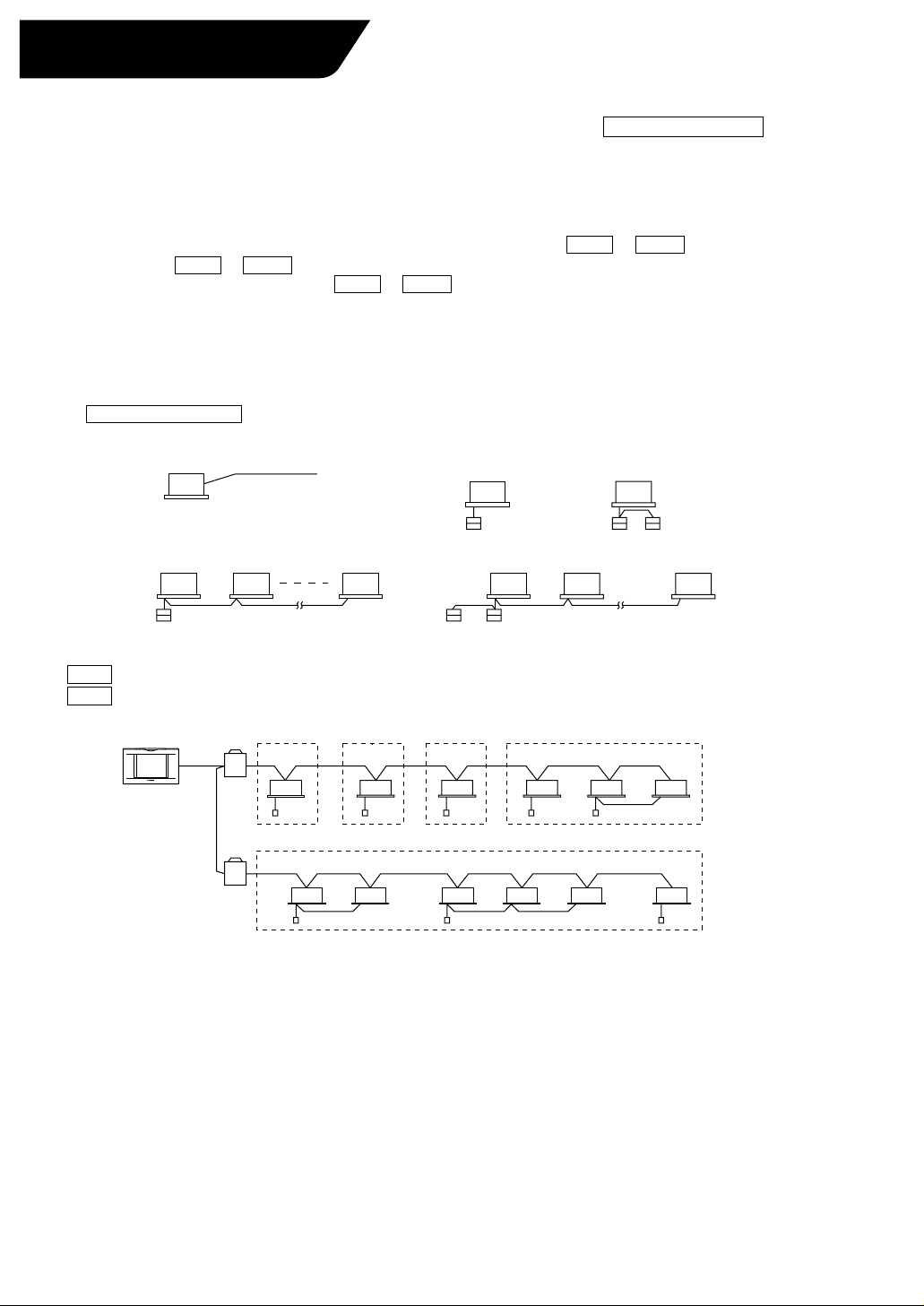
This intelligent Touch Controller is capable of controlling / monitoring up to 64 groups of indoor units henceforth
termed
Main functions of the intelligent Touch Controller:
1. Collective starting / stopping of operation of the indoor units connected to the
2. Starting / stopping of operation, temperature setting, switching between temperature control modes and
3. Scheduling by zone or group .
4. Monitoring of the operation status by zone or group .
5. Display of the air conditioner operation history.
6. Forced STOP contact input from a central monitoring panel (no voltage, normally open contact).
∗ A group of indoor units include :
group(s)
enabling / disabling of operation with the hand-held remote control by zone or group .
q One indoor unit without a remote control.
.
intelligent
w One indoor unit controlled with one or two remote controls.
Indoor unit
Touch Controller.
No remote control
e Up to 16 indoor units controlled with one or two remote controls.
Up to 16 units Up to 16 unitsTwo remote controlsRemote control
∗ Zone control with the intelligent Touch Controller
∗ Zone control, which allows collective settings for more than one group, is available with the intelligent Touch
Controller, which facilitates the setting operations.
Zone 1
intelligent Touch Controller
Zone 5
¡One setting commands all of the units in one zone.
¡Up to 128 zones can be set with one intelligent Touch Controller.
(The maximum number of groups in one zone is 64.)
¡Groups can be zoned at will with the intelligent Touch Controller.
¡Units in one group can be divided into more than one zone.
Zone 2 Zone 3 Zone 4
Remote control Remote control
or
3
Features and Functions
■ Operation Menu
The intelligent
group or zone. Collective starting / stopping is also available.
Touch Controller is capable of starting / stopping operation by the
■ Air Conditioner Detail Setup
Temperature setting, switching between temperature control modes, switching of
speed and direction of airflow and remote control mode setting are available by
the group, by the zone or collectively.
■ Monitoring of Various Information on Indoor Units
Information on operation such as the operation mode and temperature setting of
the indoor units, maintenance information including the filter or element cleaning
sign, and troubleshooting information such as error codes can be displayed by the
group or the zone.
■
Diversified Operation Modes
Operation can be controlled both with the main unit and the remote controller to
provide diversified operation management. Setting the main unit allows the
following remote control settings by the group, by the zone or collectively:
1. Start/Stop 2. Operation Mode 3.Temperature Setting
: (Remote control) Inhibited
: (Remote control) Permitted
: Priority
: (Remote control) Inhibited
: (Remote control) Permitted : (Remote control) Permitted
: (Remote control) Inhibited
See pages
15 17
to
See pages
18 22
to
See pages
26 30
to
See page
22
Before use
■
Zone Control Simplifying Complicated Setting Operations
Up to 64 groups can be controlled with the intelligent Touch Controller.
More than one group can be consolidated into a registered zone with specific
settings that apply to all groups within that zone. This eliminates the need for
repeating the same setting operation for each group. A collective setting for all
groups is also available. Available settings are:
¡Start / stop
¡Temperature setting
¡Switching between operation modes
¡Setting of direction and fan speed
¡Disabling / enabling the remote control
■ Detailed Scheduled Operation Control
The intelligent Touch Controller allows detailed scheduled operation by the group,
by the zone or collectively. Up to 8 options for the annual schedule can be set.
Each schedule can include four types of plans : Weekdays, Holidays, Special
Days 1 and Special Days 2. Each of the plans allows setting of up to 16 operations.
■ Handy Automated Control
The Intelligent Touch Controller enables the following:
¡
Automatic Changeover : automatically switches between cooling and heating
according to the room temperature.
¡
Temperature Limit : prevents the temperature from rising too high or
too low in unmanned rooms.
¡
Heating Mode Optimization : stops uncomfortable discharge from the Indoor
Unit during the Thermo-Off heating conditions.
¡
FC Change Over : automatically switches between cooling, heating and
fan, and automatically switches intaking outside air or not, according to the
room temperature and outside temperature.
See pages
15 30
to
See pages
35 36
to
See pages
37 53
to
4
Part Names and Functions
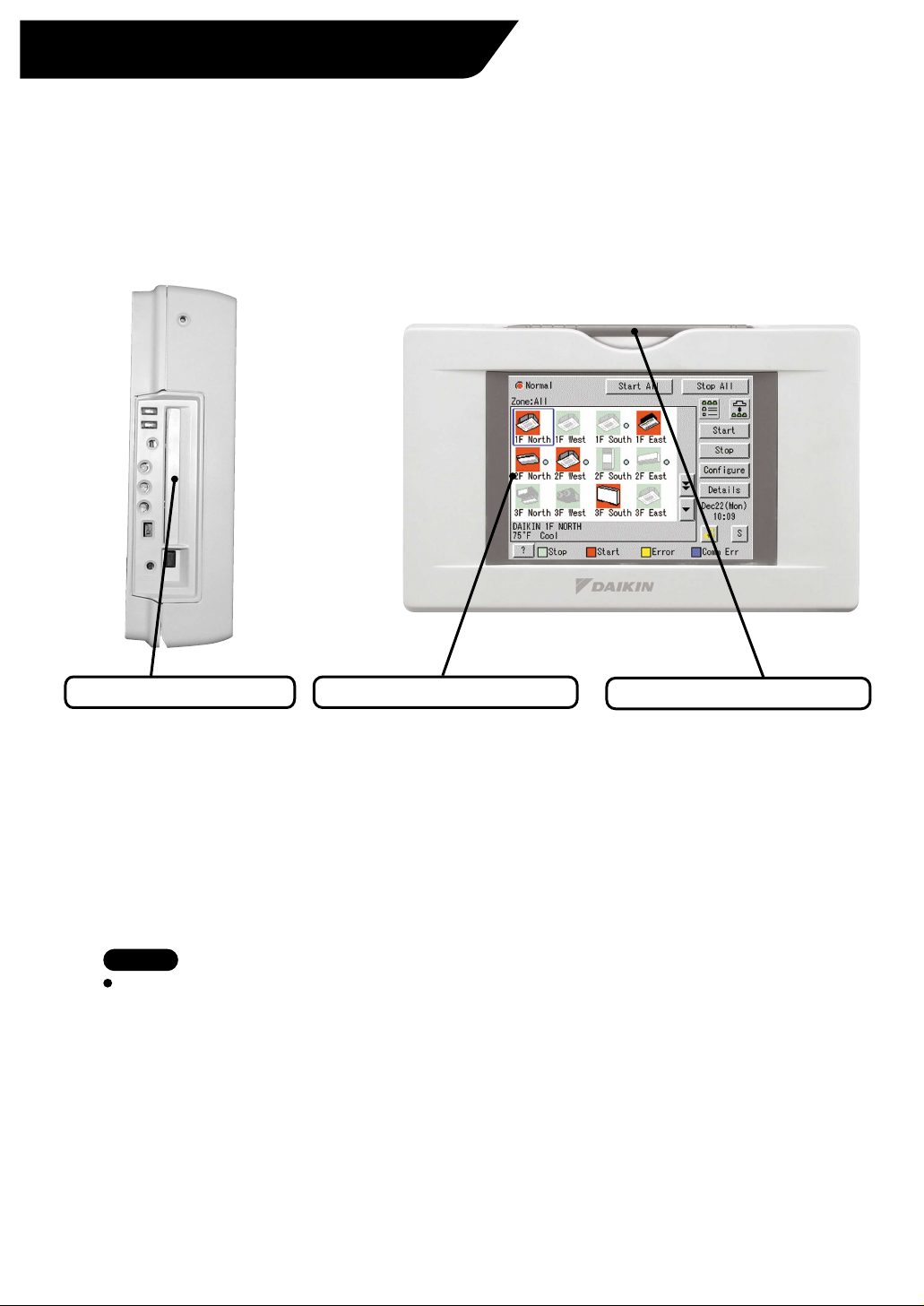
Front and Side View
PCMCIA Card Slot
Used when updating the
intelligent Touch Controller
software to a newer version and
downloading the other data.
Note
You must always use the
provided touch pen as any other
object can damage the panel.
Be sure to use the touch pen for
operation.
Color LCD with Touch Panel
Provides a display for monitoring
and operation.
Monitoring display should be
operated with the touch pen.
Be sure to use the touch pen
provided for operation.
Touch Pen
Be sure to operate with the touch
pen and take care not to lose it. In
the event it is lost, contract your
dealer.
Use the touch pen for operation.
5
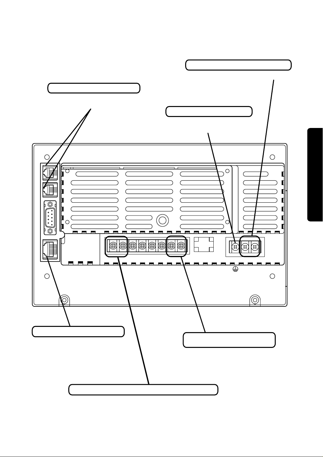
Terminals on the Back of intelligent Touch Controller
Terminal block for power supply
Connect to AC24V power supply.
Terminal size is M4.
Modem connector for AIRNET
When using AIRNET service,
connect it to the telephone line.
Earth terminal block
Securely connect the earth wire.
Terminal size is M4.
LINE
PHONE
Before use
RS-232C LAN
COM L0Dil Pi3 COM Pi2 Pi1 F2 F1
Ethernet connector for web
When monitoring and operating
the indoor units using the optional
Web and E-mail function software
sold separately, connect to LAN
via Ethernet cable.
Terminal block for force stop input of indoor units
This is used when stopping the indoor units compulsorily
by contact input.
The size of terminal block is M3.5.
24
24
VAC
VAC
COM
Terminal block for D3-NET
communication
The terminal size of the terminal
block for communication with
indoor units is M3.5.
6
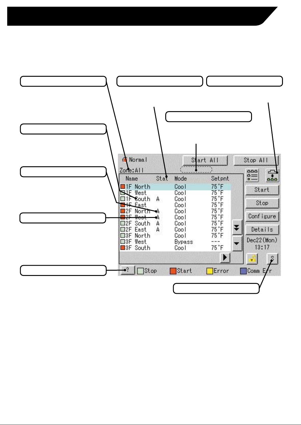
Part Names on the Monitoring Screen and the Functions
List
Contents of the List Currently Displayed
¡When Group List is displayed
Zone :
Zone Name
¡
When Zone List is displayed
Zone List
Zone / Group Name
Set the names in the Group
Registration or Zone Registration
in the System Settings Mode.
Target of Automatic Control
Displayed when any air
conditioner has a registered
schedule in the zone or group.
Filter / Element Sign
Displayed when there is any air
conditioner showing a filter or
element sign in the zone or the
group.
Zone / Group Currently Displayed
The name of the zone / group
currently selected is highlighted
in light-blue.
Display Mode Selection
Press the button and display
change between Zone and Group.
System Condition Displayed Domain
System condition such as Forced Stop and
System Error, etc. is displayed here. When
normal operation, nothing is displayed.
Monitoring Screen Legend
Pressing the “?” button shows
more detailed legend.
7
Button to Switch to the System Settings Mode
Use this button for settings
including the time, group, zone
and schedule.
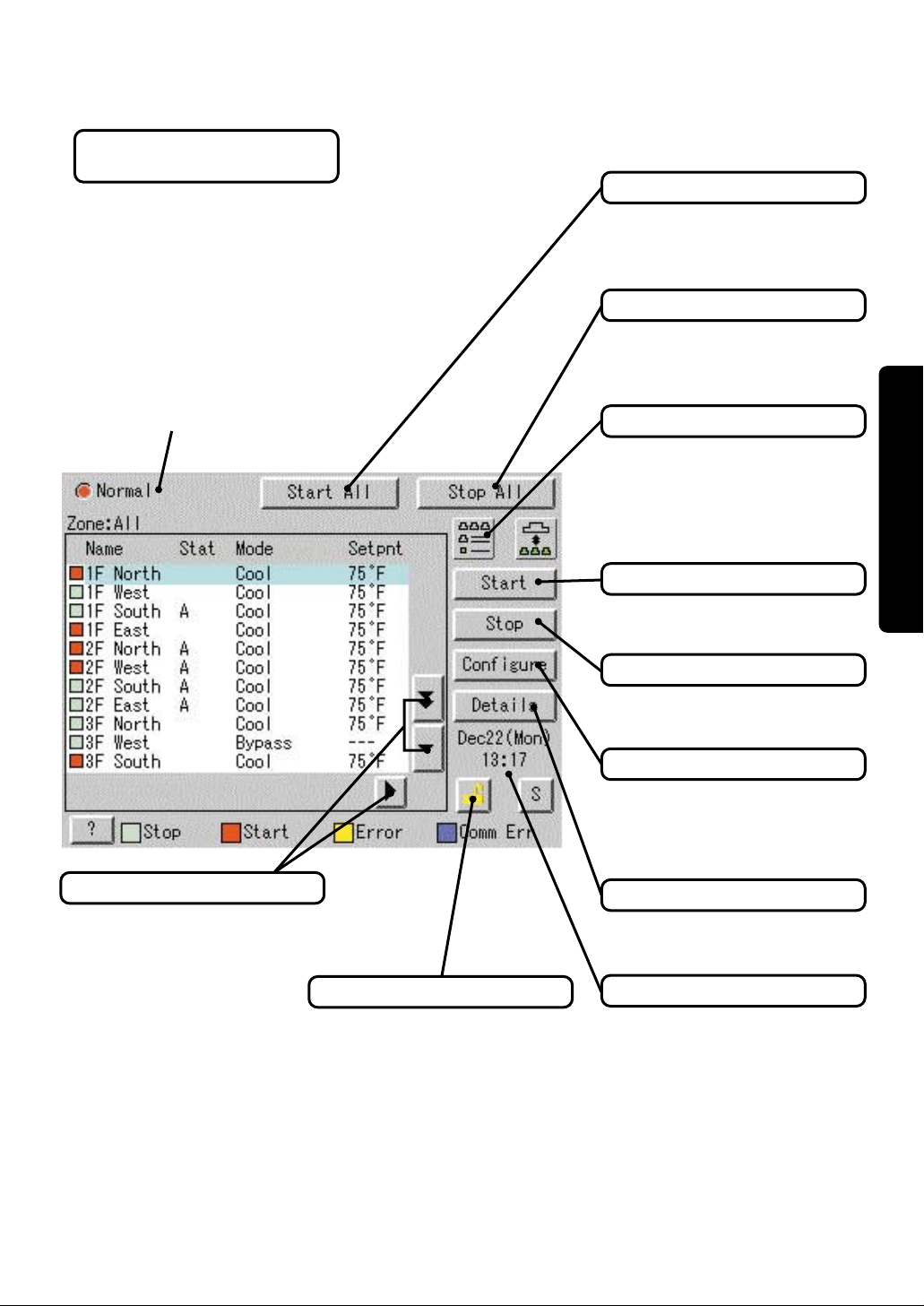
List
Display for Collective Monitoring of Air
Conditioners Connected to intelligent Touch Controller
When operation is normal and any air
conditioner is in operation :
Red / Normal
When operation is normal and all air
conditioners are in stoppage :
Green / Normal
When there is any air conditioner
generating an error :
Yellow / Abnormal
When there is any air conditioner with
communication error :
Blue / Abnormal
Change in color of Start/Stop is
possible by Iconcolor Settings in
System Settings.
Start All Button
Button to collectively start all the
air conditioners connected to
intelligent Touch Controller.
Stop All Button
Button to collectively stop all the
air conditioners connected to
intelligent Touch Controller.
Display Mode Selection
Select the mode among icon / list /
detailed icon.
See Icont Displays on Pages 9-10.
See Detailed Icon Displays on
Pages 11-12.
Group / Zone Start Button
Button to start operation of the
group / zone selected.
Before use
Scroll Buttons
Up / Down scroll button used
when monitoring zone / group
which are not currently displayed.
Left / Right scroll button to locate
areas to monitor not visible on
screen.
Lock Setting / Cancel Button
Displays if monitor is locked or
available to use. See detailed
information on Page 31.
Group / Zone Stop Button
Button to stop operation of the
group / zone selected.
Group / Zone Configure Button
Makes settings (temperature
setting, temperature control mode,
etc.) and display of the group /
zone selected.
Group / Zone Details Button
Detailed display of the group /
zone selected
Current Time Display
Shows the current date and time.
8

Icon
Contents of the List Currently Displayed
¡The particular Zone being
monitored appears here.
Zone :
Zone Name
¡When Zone List is displayed
Zone List Display
Zone / Group Currently Displayed
The name of the zone / group currently
selected is highlighted in blue flame.
Filter / Element Sign
Displayed when there is any air
conditioner showing a filter or
element sign in the zone or the
group.
Zone / Group Name
Set the names in the Group
Registration or Zone Registration
in the System Settings Mode.
Target of Automatic Control
Displayed when any air
conditioner has a registered
schedule in the zone or group.
Description of Zone / Group
Set the names in the Group
Registration or Zone Registration
in the System Setup Mode.
Display Mode Selection
Select between Zone and Group.
System Condition Displayed Domain
System condition such as Forced Stop and
System Error, etc. is displayed here. When
normal operation, nothing is displayed.
Monitoring Screen Legend
Pressing the “?” button shows
more detailed legend.
Information on Zone / Group Currently Displayed
Generally, the temperature setting
and the operation mode are
displayed. If any error occurs in the
air conditioner, the error code is
displayed.
9
Displayed Abnormality in Air Conditioner or Communication
Blue or Yellow triangles indicate an
abnormality in the air conditioner.
Button to Switch to the System Settings Mode
Use this button for settings
including the time, group, zone
and schedule.
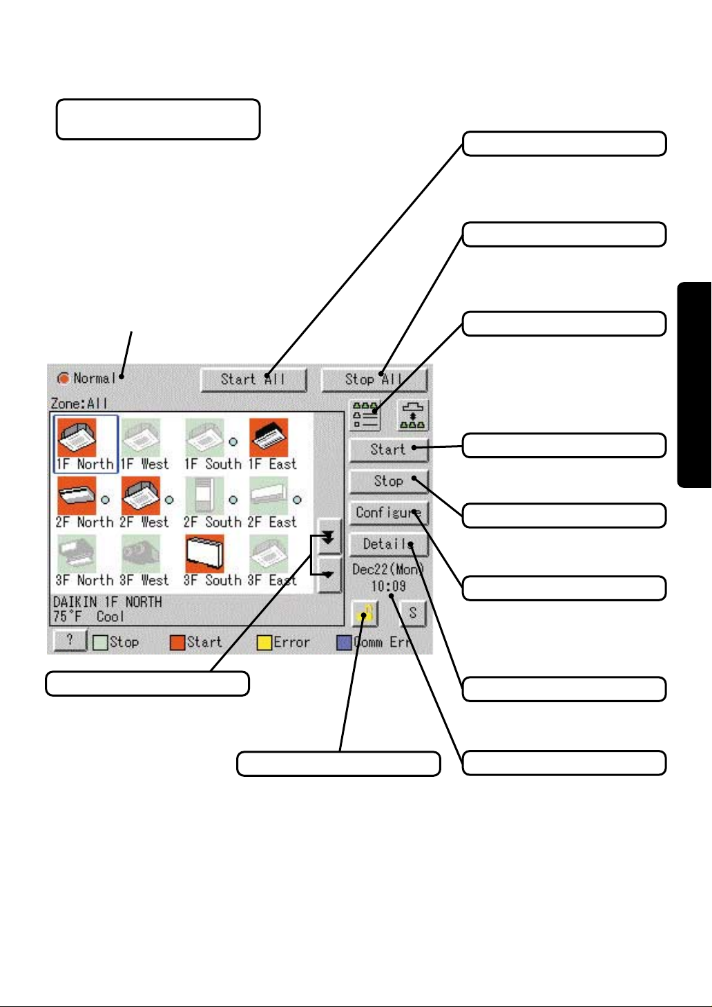
Icon
Display for Collective Monitoring of Air
Conditioners Connected to intelligent Touch Controller
When operation is normal and any air
conditioner is in operation :
Red / Normal
When operation is normal and all air
conditioners are in stoppage :
Green / Normal
When there is any air conditioner
generating an error :
Yellow / Abnormal
When there is any air conditioner with
communication error :
Blue / Abnormal
Change in color of Start / Stop is
possible by Iconcolor Settings in
System Settings.
Start All Button
Button to collectively start all the
air conditioners connected to
intelligent Touch Controller.
Stop All Button
Button to collectively stop all the
air conditioners connected to
intelligent Touch Controller.
Display Mode Selection
Select the mode among icon / list /
detailed icon.
See List Displays on Pages 7-8.
See Detailed Icon Displays on
Pages 11-12.
Before use
Group / Zone Start Button
Button to start operation of the
group / zone selected.
Scroll Buttons
Up / Down scroll button used
when monitoring zone / group
which are not currently displayed.
Lock Setting / Cancel Button
Displays if monitor is locked or
available to use. See detailed
information on Page 31.
Group / Zone Stop Button
Button to stop operation of the
group / zone selected.
Group / Zone Configure Button
Makes settings (temperature
setting, temperature control mode,
etc.) and display of the group /
zone selected.
Group / Zone Details Button
Detailed display of the group /
zone selected
Current Time Display
Shows the current date and time.
10
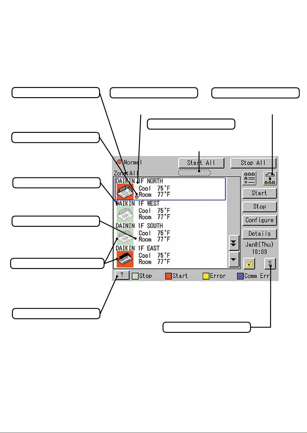
Icon
Contents of the List Currently Displayed
¡The particular Zone being
monitored appears here.
Zone :
Zone Name
¡When Zone List is displayed
Zone List Display
Filter / Element Sign
Displayed when there is any air
conditioner showing a filter or
element sign in the zone or the
group.
Zone / Group Currently Displayed
The name of the zone / group currently
selected is highlighted in blue frame.
System Condition Displayed Domain
System condition such as Forced Stop and
System Error, etc. is displayed here. When
normal operation, nothing is displayed.
Zone / Group Name
Set the names in the Group
Registration or Zone Registration
in the System Settings Mode.
Target of Automatic Control
Displayed when any air
conditioner has a registered
schedule in the zone or group.
Displayed Abnormality in Air Conditioner or Communication
Blue triangular mark shows
communication abnormality in air
conditioner.
Yellow triangular mark shows
abnormality in air conditioner.
Display Mode Selection
Press the button ana display
change between Zone and Group.
Monitoring Screen Legend
Pressing the “?” button shows
more detailed legend.
11
Button to Switch to the System Settings Mode
Use this button for settings
including the time, group, zone
and schedule.
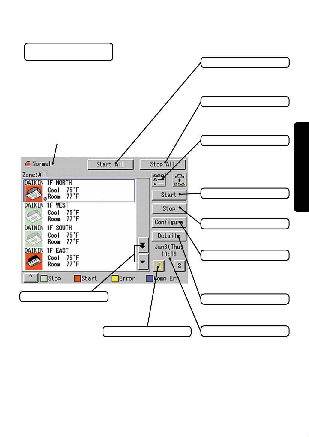
Icon
Display for Collective Monitoring of Air
Conditioners Connected to intelligent Touch Controller
When operation is normal and any air
conditioner is in operation :
Red / Normal
When operation is normal and all air
conditioners are in stoppage :
Green / Normal
When there is any air conditioner
generating an error :
Yellow / Abnormal
When there is any air conditioner with
communication error :
Blue / Abnormal
Change in color of Start / Stop is
possible by Iconcolor Settings in
System Settings.
Start All Button
Button to collectively start all the
air conditioners connected to
intelligent Touch Controller.
Stop All Button
Button to collectively stop all the
air conditioners connected to
intelligent Touch Controller.
Display Mode Selection
Select the mode among icon / list /
detailed icon.
See List Displays on Pages 7-8.
See Icon Displays on Pages 9-10.
Before use
Group / Zone Start Button
Button to start operation of the
group / zone selected.
Scroll Buttons
Up / Down scroll button used
when monitoring zone/group
which are not currently displayed.
Lock Setting / Cancel Button
Displays if monitor is locked or
available to use. See detailed
information on Page 31.
Group / Zone Stop Button
Button to stop operation of the
group / zone selected.
Group / Zone Configure Button
Makes settings (temperature
setting, temperature control mode,
etc.) and display of the group /
zone selected.
Group / Zone Details Button
Detailed display of the group /
zone selected
Current Time Display
Shows the current date and time.
12
Quick Reference
Air Conditioner Operation
■ To collectively start / stop the operation of all devices connected
to the intelligent Touch Controller
■ To start / stop the operation of devices by group
■ To start / stop the operation of devices by zone
■ To change the operation mode
■ To change the temperature setting
■ To reset the filter or element sign
■ To change the direction or fan speed
■ To change the range of operation allowed with remote control
■ To change the ventilation mode
■ To change the ventilation volume
■ To permit / prohibit the remote control at hand for ventilation
See page
See page
See page
See page
See page
See page
See page
See page
See page
See page
See page
15
16
17
18
19
20
21
22
23
24
25
Air Conditioner Operation Monitoring
■ To monitor by zone or by group
■ To monitor detailed information
■ To monitor the operation condition for ventilation
■ To set / release the lock of screen operation
13
See pages to
See pages to
See page
See page
26 27
28 29
30
31
System Settings Menu
■ To change the name of a group
■ To change the zone settings
■ To change the schedule
■ To change the Automatic Changeover
■ To change the temperature limit
■ To change the heating optimization settings
■ To change the FC Change Over settings
■ To calibrate the touch panel
■ To review the history of errors
■ To set the locale
■ To set the icon color
See page
See page
See pages to
See pages to
See pages to
See pages to
See pages to
See page
See page
See page
See page
33
33
35 36
37 41
42 44
45 46
47 53
62
62
34
34
■ To set the network
■ To set the activation key
■ To adjust the contrast of the screen
■ To set the e-mail
■ To set the Simple Interlock
See page
See page
See page
See pages to
See pages to
34
34
105
54
57 61
Operation
56
14
Air Conditioner Operation
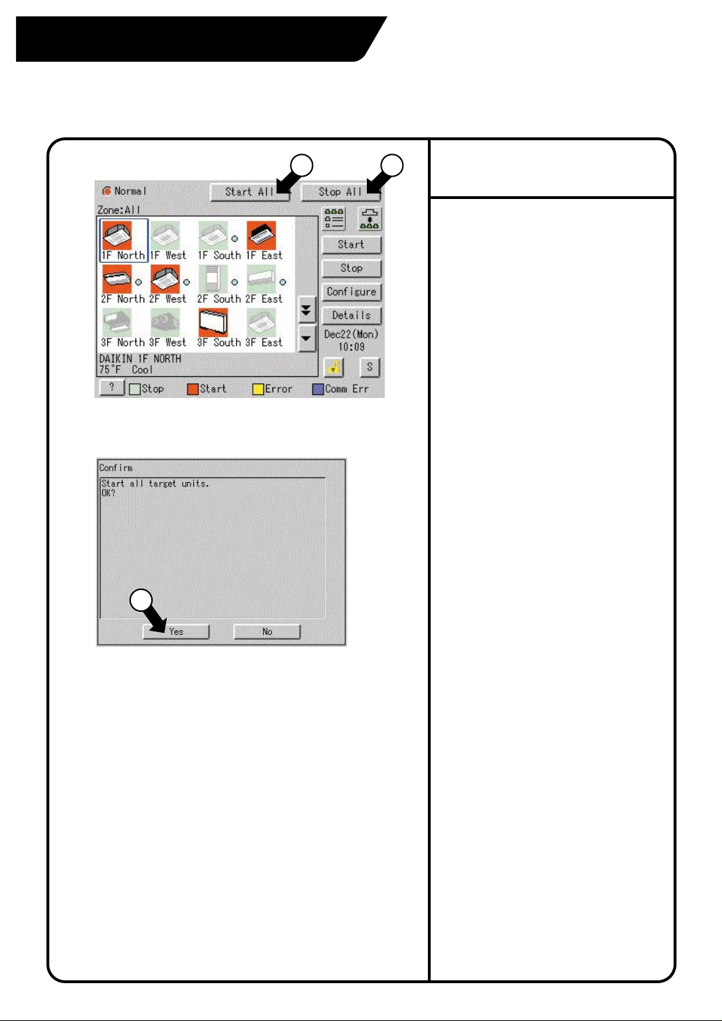
Starting / Stopping Operation Collectively
Screen 1 Monitoring
Screen 2 Confirm
1 2
To start / stop the operation
of all devices connected
Start or stop collectively the operation of
devices connected.
On the Monitoring screen, operation is
allowed with either Zone or Group as the
display mode and with either Icon or List as
the display type. In the example on the left,
the display mode is Group in the collective
mode and the display type is Icon.
[Procedure]
On Screen 1 Monitoring, press the [Start
1.
All] button q or [Stop All] button w .
2.
Screen 2 appears to confirm. Press the
[Yes] button e.
To exit without activating collective
start or stop, press the [No] button.
15
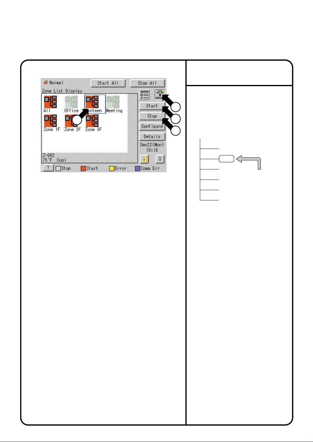
3
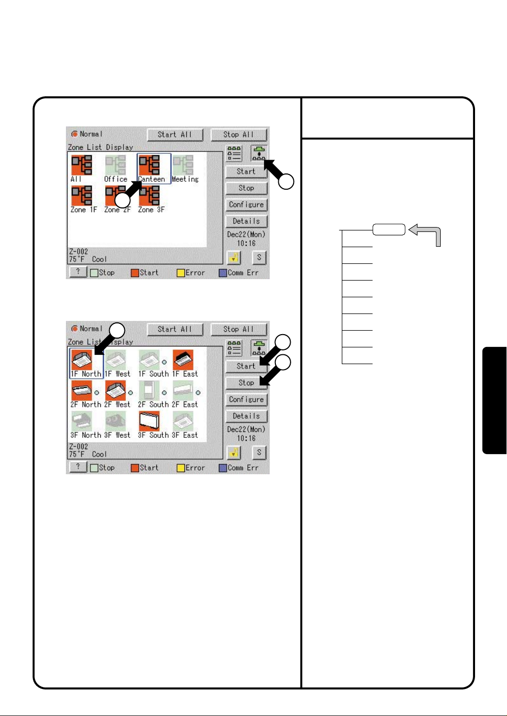
Starting / Stopping Operation by the Group
Screen 1 Monitoring
2
Screen 2 Monitoring (Group)
3
To start / stop the operation
of devices by group
Start or stop the operation of air conditioners
by group.
The example on the left shows the
1
screen for starting / stopping the
operation of Group Name : 1F North
registered for Zone Name : Canteen.
Zone Name
Canteen
4
5
[Procedure]
1F North
1F West
1F South
1F East
2F North
2F West
2F South
2F East
3F North
Air conditioner
group to be
started or
stopped
On Screen 1 Monitoring, select a zone
1.
from the button q.
Select a zone that includes the group of
2.
which the operation is to be started or
stopped w.
Select a group from the button q.
3.
Screen 2 Monitoring (Group) appears.
Select a group to be started or stopped
4.
as in e and press the [Start] button r
or [Stop] button t.
Operation
16
Starting / Stopping Operation by the Zone
Screen 1 Monitoring
2
To start / stop the operation
of devices by group
Start or stop by zone the operation of groups
of air conditioners set in zones.
1
The example on the left shows a screen for
starting or stopping the operation of air
conditioners in the canteen.
3
4
Zone Name
Collective Zone
Office
Canteen
Meeting
1F
2F
3F
Air conditioner
group to be
started or
stopped
[Procedure]
On Screen 1 Monitoring, select a zone
1.
from the button q.
Select the zone of which the operation is
2.
to be started / stopped as shown in w.
3.
Press the [Start] button e or [Stop]
button r.
17
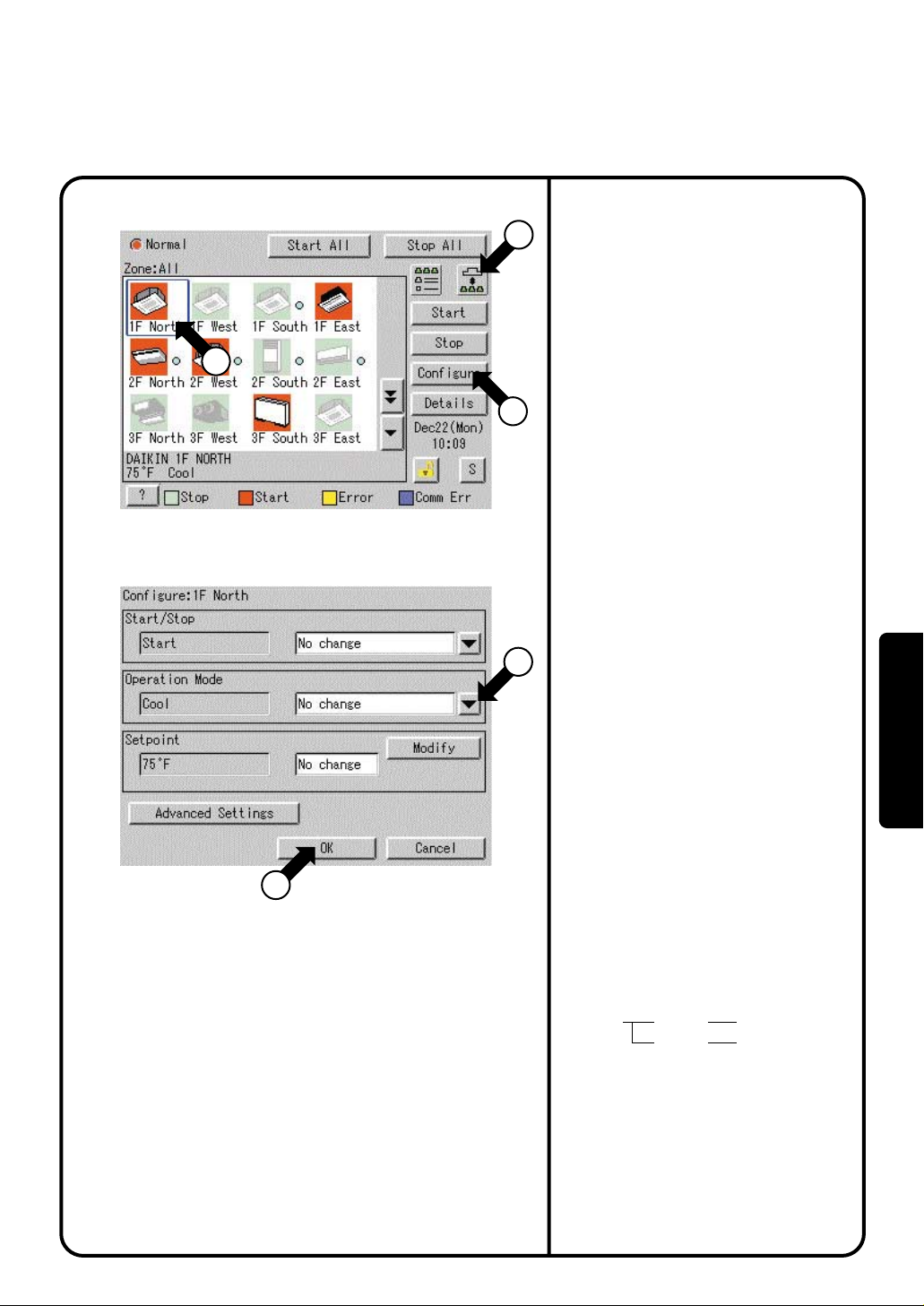
Switching the Operation Mode
Screen 1 Monitoring
2
Screen 2 Operation
1
3
[Procedure]
4
Switch the operation mode of the air
conditioner.
On the Monitoring screen, operation is
allowed with either Icon or List as the display
type.
The operation mode can be switched by
zone or by group.
Selecting a zone and switching the
operation mode switches the mode of
all air conditioners in the zone.
Selecting a group and switching the
operation mode switches the mode of air
conditioners in the group selected.
On Screen 1 Monitoring, select a zone
1.
or a group from the button q.
Select with w a zone or a group of
2.
which the operation mode is to be
switched.
3.
Press the [Configure] button e.
Screen 2 Operation is displayed.
Select the operation mode to be set
4.
from the pull down menu r.
On the menu, operation modes
available for air conditioners in the
zone are displayed if the switching is
to be made by zone. See the
example below.
Operation
Press the [OK] button t.
5.
To cancel the setting, press the Cancel
button.
5
Ex.: For the following zone setting, the
operation modes available are Fan,
Cool, Heat and Auto.
If Changeover option is not available for
any air conditioner in the zone, Fan and
Dependent are the available operation
modes.
Zone name Group name
Canteen
1F North
1F West
Operation modes available
Cool Fan
Cool Heat
Auto Fan
18
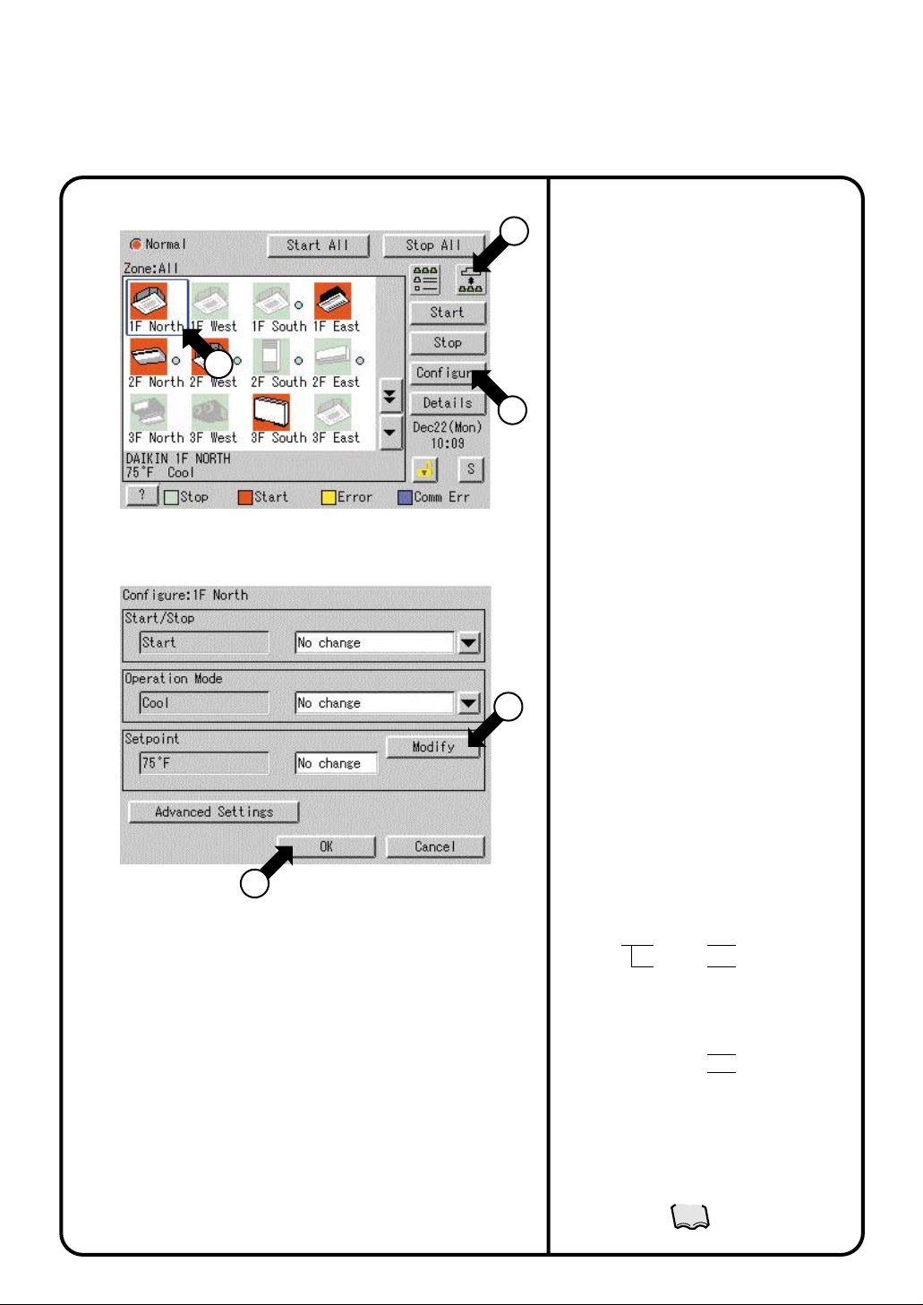
Changing the Temperature Setting
Screen 1 Monitoring
2
Screen 2 Operation
1
3
[Procedure]
4
Change the temperature setting of air conditioners.
On the Monitoring screen, operation is allowed
with either Icon or List as the display type.
The temperature setting can be switched by zone
or by group.
Selecting a zone and changing the temperature
setting changes the setting of the air conditioner
groups in each selected operation in the zone.
Selecting a group and changing the temperature
setting changes the temperature setting of air
conditioners in the group selected.
If all of the air conditioners in the group selected
are in Fan operation, temperature setting cannot
be changed.
On Screen 1 Monitoring, select a zone or a
1.
group from the button q.
Select a zone or a group of which the
2.
temperature setting is to be changed w.
Press the [Configure] button e.
3.
Screen 2 Operation is displayed.
For temperature setting, press the [Modify]
4.
button r.
Setpoint dialog is displayed and input
temperature for setting.
On the menu, temperature settings
available for air conditioners in the zone are
displayed if the setting is to be made by the
zone. See the example below.
19
5.
Press the [OK] button
To cancel the setting, press the [Cancel]
button.
Ex.: For the following zone setting, the
temperature settings available are between
5
68°F and 86°F inclusive.
Zone name Group name
Canteen
When the temperature setting is 86°F, the
actual temperature settings for air
conditioners are as shown below:
Note: Range of temperature settings available is
the range specified in accordance with the
following.
¡
the air conditioner main unit.
¡
restriction by the temperature setting limit.
1F North 11 to 86
1F West
Group name
1F North 86
1F West
Range of temperature setting inherent to
Range of temperature as a result of the
See page
67
t
.
Range of temperature
settings available
(see Note)
°F
68 to 77
°F
Temperature setting
°F
77
°F
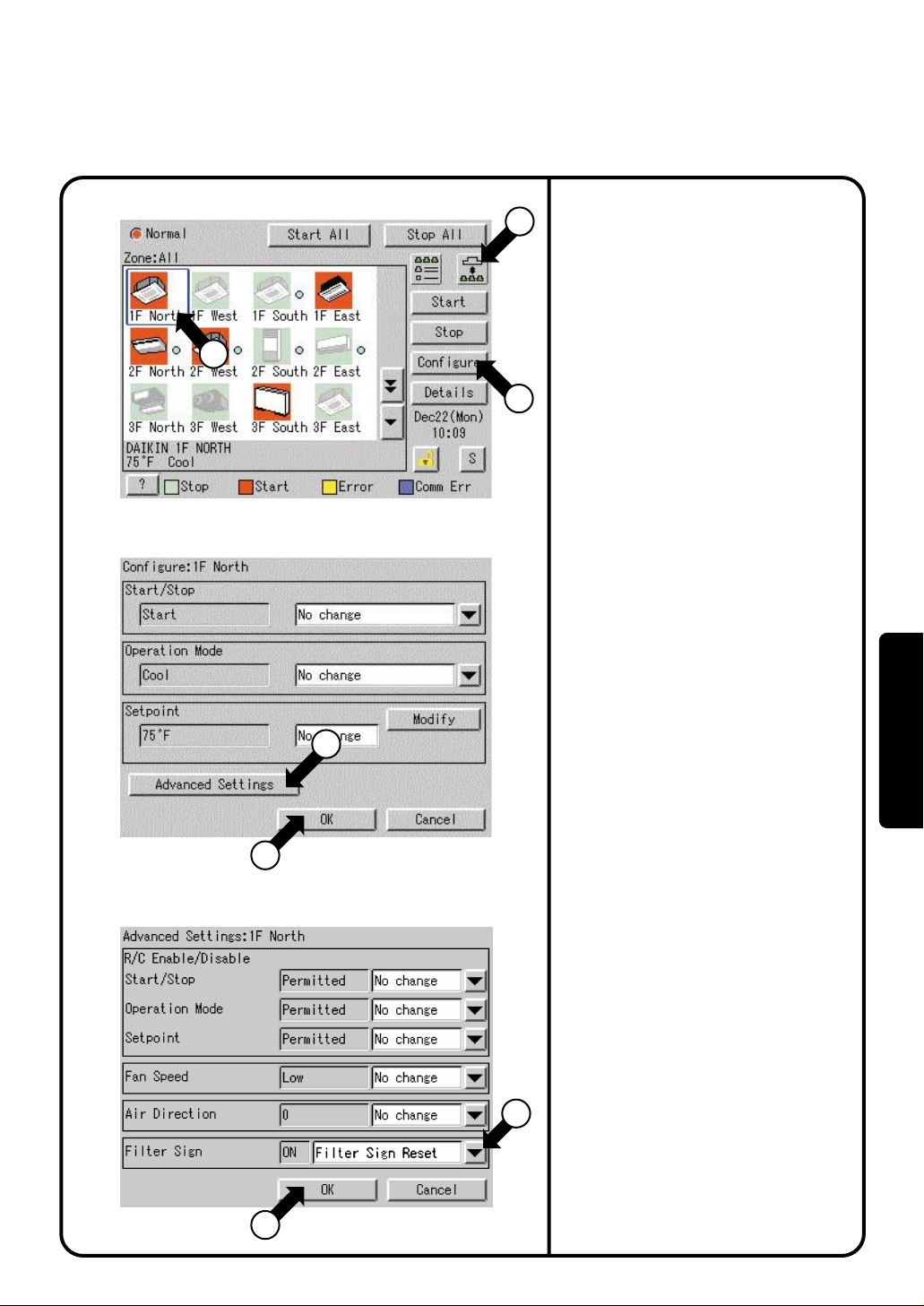
Resetting the Filter / Element Sign
Screen 1 Monitoring
2
Screen 2 Operation
Reset the filter or element sign after
1
cleaning any air conditioner showing the
filter or element sign.
On the Monitoring screen, operation is
allowed with either Icon or List as the display
type.
The filter or element sign can be reset by
zone or by group.
[Procedure]
3
4
On Screen 1 Monitoring, select a zone
1.
or a group from the button q.
2.
Select a zone or a group of which the
filter or element sign is to be reset w.
3.
Press the [Configure] button e.
Screen 2 Operation is displayed.
Press the [Advanced Settings] button r.
4.
Screen 3 Advance Operation is displayed.
To reset the filter / element sign, select
5.
Filter Sign Reset
Then press the [OK] button y.
To cancel the setting, press the
[
Cancel] button.
Screen 2 Operation is displayed again.
Then press the
6.
2 Operation.
To cancel the setting, press the
[
Cancel] button.
in pull-down menu
[OK]
button u on Screen
t.
Operation
7
Screen 3 Advanced Settings
6
5
20
Changing the Direction / Fan Speed
Screen 1 Monitoring
2
Screen 2 Operation
8
Screen 3 Advanced Settings
Change the air direction or volume of air
1
conditioners.
On the Monitoring screen, operation is allowed
with either Icon or List as the display type.
The air direction or volume can be changed by
zone or by group.
[Procedure]
On Screen 1 Monitoring, select a zone
1.
or a group from the button q.
3
4
Select a zone or a group of which the
2.
air direction or volume is to be reset w.
Press the [Configure] button e.
3.
Screen 2 Operation is displayed.
4.
Press the [Advanced Settings] button r.
Screen 3 Advance
Set the direction with the pull-down
5.
menu y.
The larger the value for wind direction
setting (0 - 6), the closer to vertical the
direction becomes. The value 7 indicates
automatic swing.
(Note: See the figure below.)
The description given above may not
exactly apply depending on the model.
Check the airflow direction sign on the
remote control after operation.
Select the Fan Speed with the pull-down
menu t.
Then press the [OK] button u.
To cancel the setting, press the
[Cancel] button.
Screen 2 Operation is displayed again.
Then press the
6.
2 Operation.
To cancel the setting, press the
[Cancel] button.
Settings
is displayed.
[OK]
button i on Screen
21
Note: Guidelines for airflow direction value and
actual direction
Indoor unit
5
6
0
4
5
6 7: Airflow direction auto
swing
7
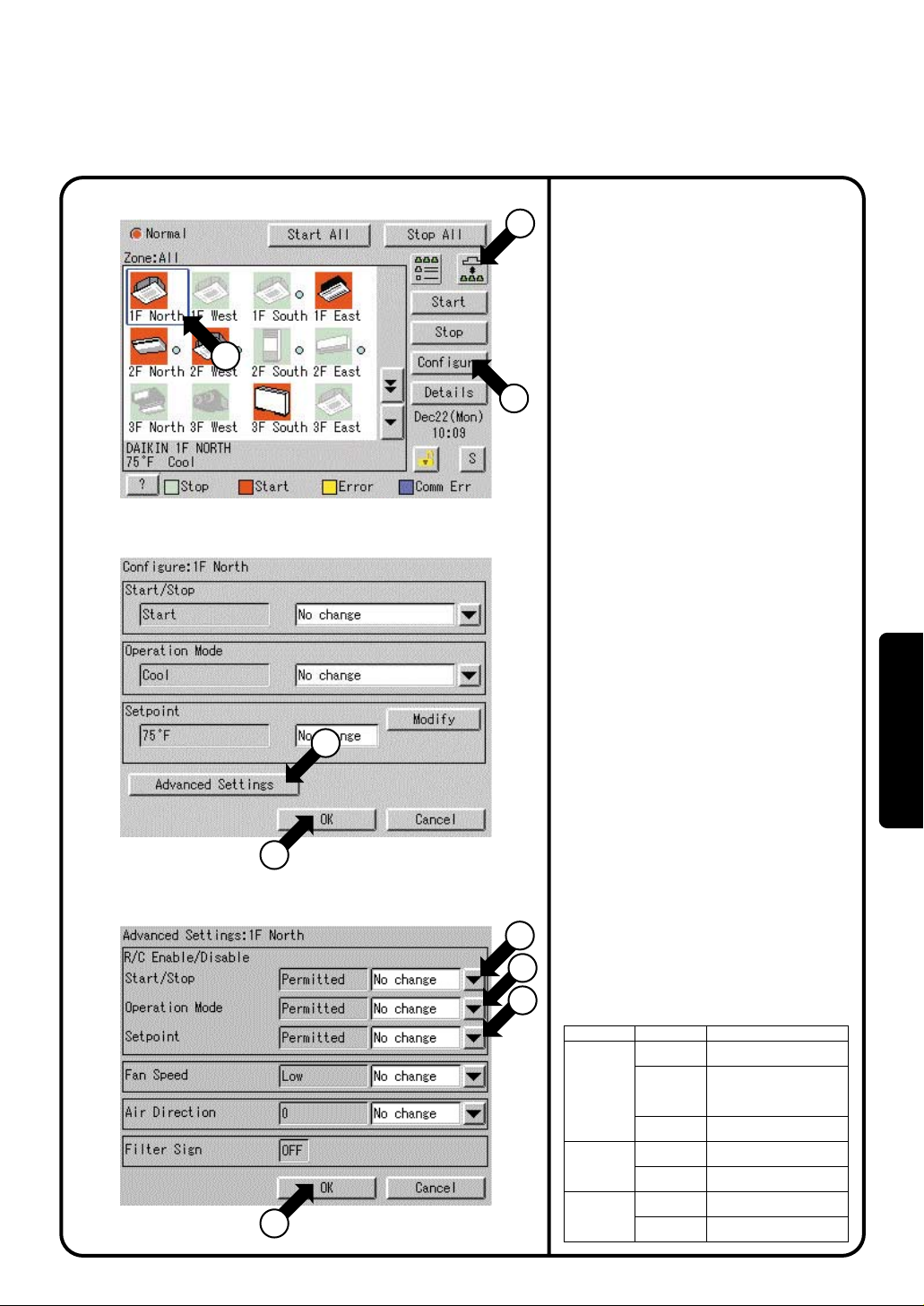
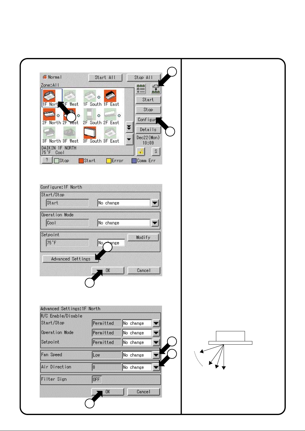
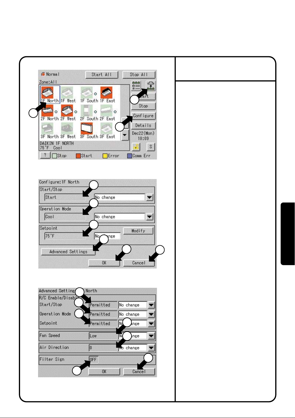
Changing the Range of Operation Allowed with Remote Control
Screen 1 Monitoring
2
Screen 2 Operation
9
Screen 3 Advanced Settings
8
Change the setting of operation with the remote
control of air conditioners between Permitted and
1
Prohibited.
On the Monitoring screen, operation is allowed
with either Icon or List as the display type.
The setting between Permitted and Prohibited
can be changed by zone or by group.
[Procedure]
On Screen 1 Monitoring, select a zone
1.
3
4
5
6
7
or a group from button q.
Select with w a zone or a group for which
2.
the setting of the range of operation
allowed with remote control is to be reset.
Press the [Configure] button e.
3.
Screen 2 Operation is displayed.
Press the [Advanced Settings] button r.
4.
Screen 3 Advance Settings is displayed.
Then make setting with the pull-down
5.
menus t - u.
There are three settings as shown below:
tStart/Stop
Prohibited
Stop Only
Permitted
No change
yOperation Mode
Permitted
No change
uSetpoint
Permitted
No change
Press the [OK] button i after setting
t - u.
To cancel the setting, press the
[Cancel] button.
Screen 2 Operation is displayed again.
Then press the [OK] button o on Screen
6.
2 Operation.
To cancel the setting, press the
[Cancel] button.
or
Prohibited
or
Prohibited
[Details of Setting]
Item Setting Meaning
Prohibited
Start/Stop
Operation
Mode
Setpoint
Stop Only
Permitted
Permitted
Prohibited
Permitted
Prohibited
The remote control cannot
start or stop operation.
The remote control can stop the
operation of air conditioners in
operation but cannot start air
conditioners not in operation.
The remote control can start
or stop operation.
The remote control can
change the operation mode.
The remote control cannot
change the operation mode.
The remote control can change
the temperature setting.
The remote control cannot
change the temperature setting.
Operation
22
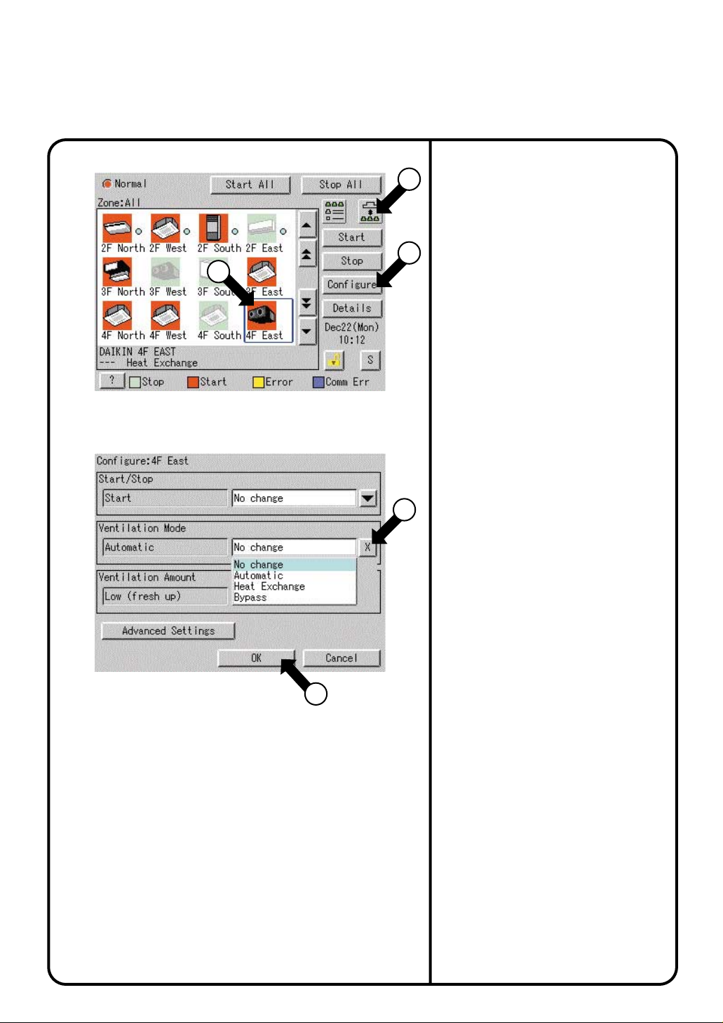
Set Ventilation Mode
Screen 1 Monitoring (Icon)
2
Screen 2 Operation
Perform the following procedure to switch
the ventilation mode:
1
On the monitoring screen, you can select
any of the following display types:
Icon, Detailed Icon, or List.
When changing the ventilation modes of all
the ventilation groups of a zone, select the
3
zone and switch the ventilation mode.
When changing the ventilation mode of a
group, select the group and switch the
ventilation mode.
[Procedure]
1.
2.
3.
4.
4
5.
∗
On Monitoring Screen Screen 1, select
a zone or group by pushing the button q
To select a zone or group subject to
ventilation mode switching, push the icon w.
Push [Configure] button e to display
Operation Screen Screen 2.
Select a desired ventilation mode on
the pull-down menu r.
Last, press [OK] button t.
To cancel above settings, press
[Cancel] button.
Not all models permit the above settings.
.
23
5
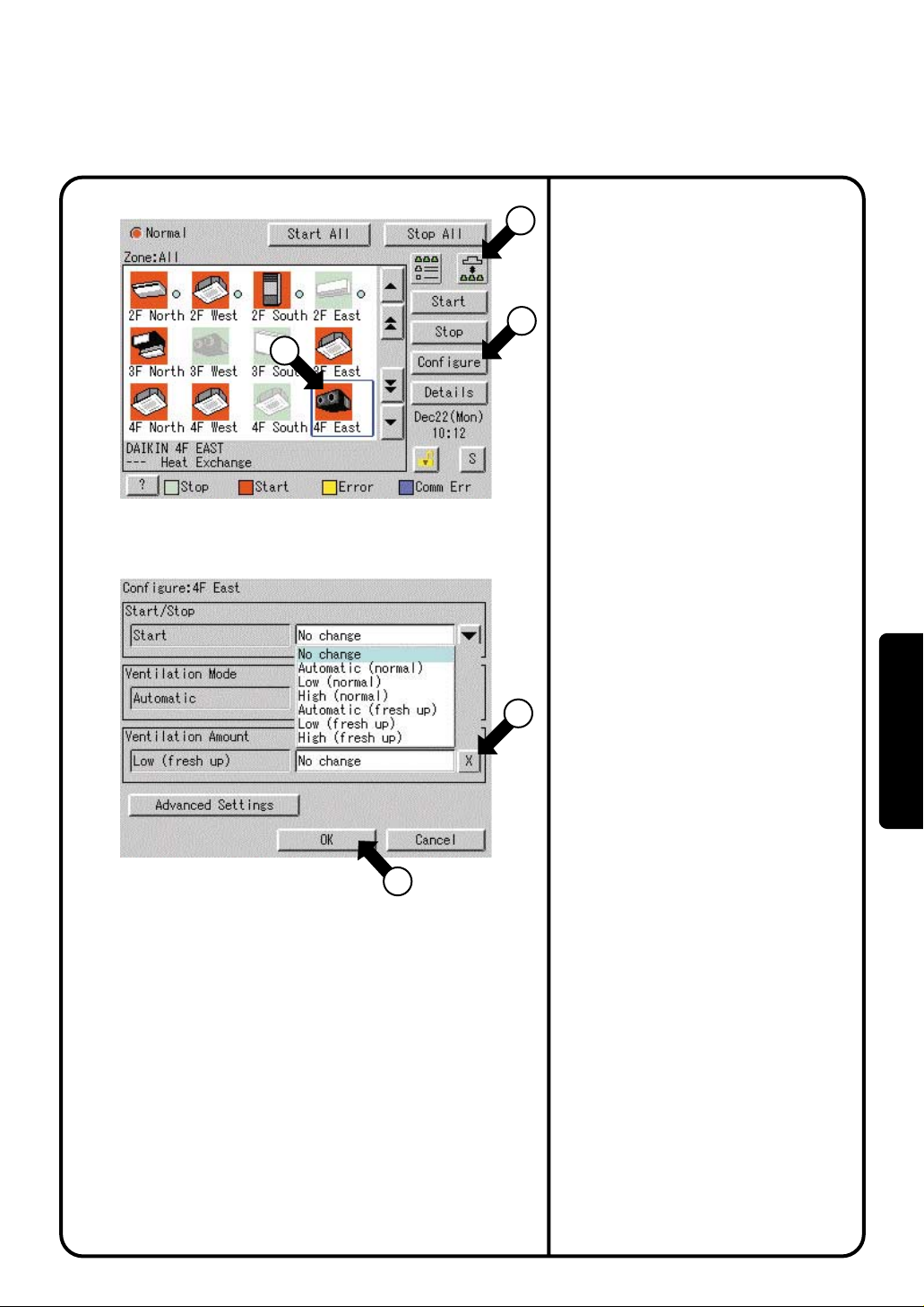
Set Ventilation Volume
Screen 1 Monitoring
Screen 2 Operation
Perform the following procedure to change
the ventilation volume:
1
On the monitoring screen, you can select
any of the following display types:
Icon, Detailed Icon, or List.
When changing the ventilation volumes of all
the ventilation groups of a zone, select the
3
zone and switch the ventilation volume.
2
When changing the ventilation volume of a
group, select the group and switch the
ventilation volume.
[Procedure]
On the Monitoring Screen Screen 1,
1.
select a zone or group by pushing the
button q.
To select a zone or group subject to
2.
ventilation volume switching, push the
icon w.
Push [Configure] button e to display
3.
Operation Screen Screen 2.
Select a desired ventilation volume on
4.
the pull-down menu r.
Lastly, push [OK] button t.
5.
To cancel above settings, press
4
[Cancel] button.
∗ Not all models permit the above settings.
Operation
5
24
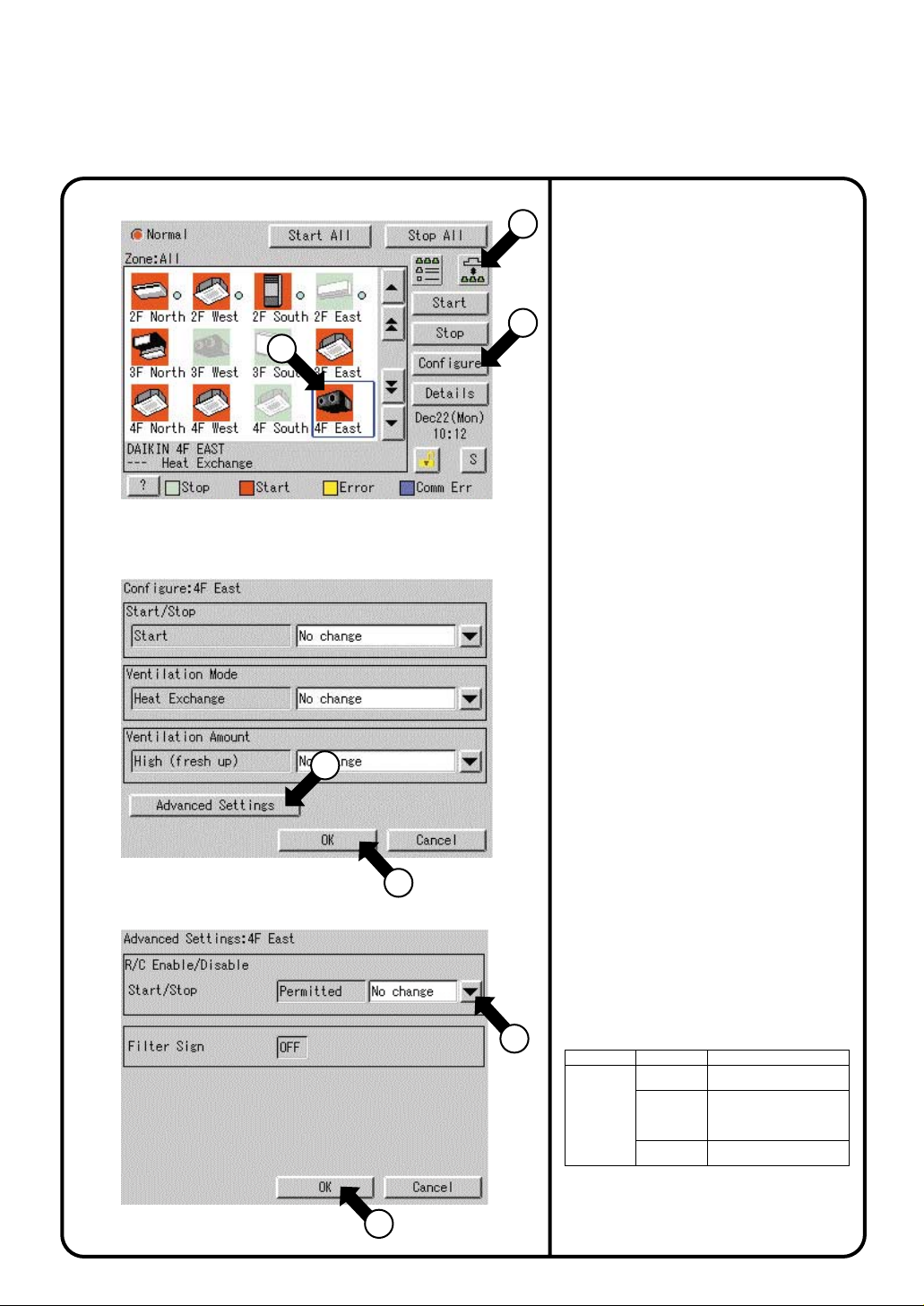
Permit / Inhibit setting of Ventilation Remote Control Operations
Screen 1 Monitoring
2
Screen 2 Operation
Screen 3 Advanced Settings
Perform the following procedure to enable or
disable the ventilation remote control
1
operations:
On the monitoring screen, you can select
any of the following display types:
Icon, Detailed Icon, or List.
You may enable or disable the remote
3
control operations in units of zones or
groups.
[Procedure]
On the Monitoring Screen Screen 1,
1.
select a zone or group by pushing the
button q.
To select a zone or group subject to
2.
ventilation volume switching, push the
icon
w.
Push [Configure] button e to display
3.
the Set Screen Screen 2.
Push [Advanced Settings] button r to
4.
display the Advanced Settings Screen
Screen 3.
Make a desired setting on the pull-down
5.
menu t.
You can enable or disable the following
setup items for remote control:
Prohibited
Stop Only
Permitted
4
7
No change
After making the setting, push [OK]
button y to display the Set Screen
Screen 2 again.
To cancel above settings, push
[Cancel] button.
Lastly, push [OK] button u on the Set
6.
Screen.
To cancel above settings, push
[Cancel] button.
25
∗ Not all models permit the above settings.
[Details of Setting]
5
Item Setting Meaning
Prohibited
Start/Stop
Stop Only
Permitted
The remote control cannot
start or stop operation.
The remote control can stop the
operation of air conditioners in
operation but cannot start air
conditioners not in operation.
The remote control can start
or stop operation.
6
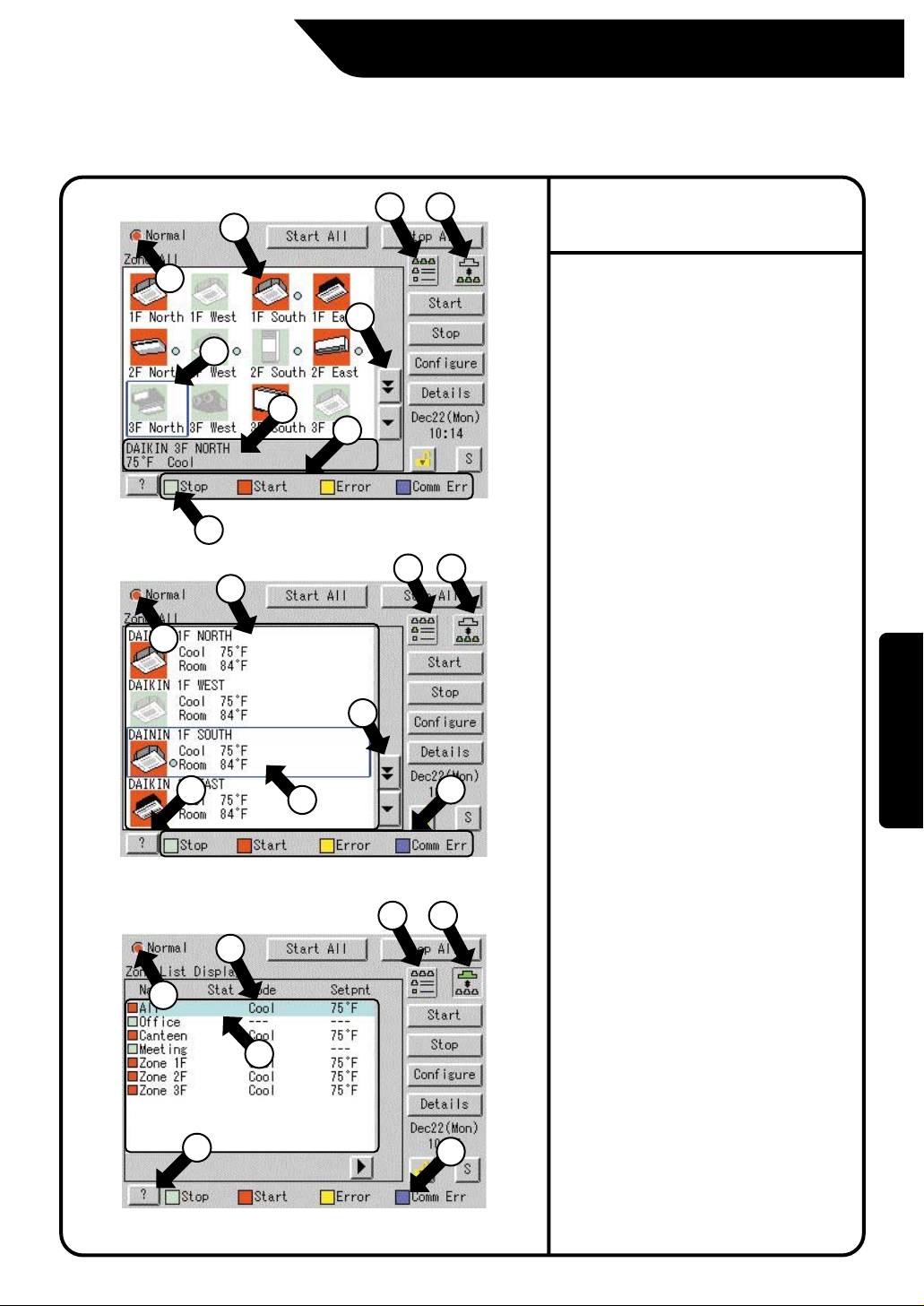
Monitoring Operation of Air Conditioner
Monitor Zone or Group Operation Status
Screen 1 Monitoring (Icon Display)
3
9
8
7
5
6
Screen 2 Monitoring
(Detailed Icon Display)
3
9
6
Screen 3 Monitoring (List Display)
8
3
9
8
6
12
Monitor Zone or Group
Operation Status
On the monitoring screen, you can select
any of the following display types:
4
12
4
5
12
5
Icon, Detailed Icon, or List.
Push the button w to select a display type.
Display type selection takes place
repeatedly in the order of icon, detailed icon
and list.
You may monitor the operation status in
units of zones or groups.
Examples of display types are shown in left
figures.
Screen 1 Display type : Icon
Screen 2 Display type : Detailed icon
Screen 3 Display type : List
Unit of monitoring : Group
Unit of monitoring : Group
Unit of monitoring : Zone
[Descriptions of Display Items on the Screen]
At e displays information concerning a zone
or group, including the operation active or
inactive status and the presence / absence
of faults, automatic control settings, filters
and element signs, etc.
Push the button r to change a display scope.
When the number of registered zones or
groups is small and all the zones or groups
can be displayed within one screen, this
button does not appear. See Screen 3.
Display of t indicates a legend.
When requiring a more detailed legend,
display the Legend Description Screen
Screen 4 on the next page by pushing the
[?] button y.
To return to the previous screen, push Close
button.
i displays the current zone or group.
You may select another zone or group by
pushing the screen.
On Screen 1, u displays the settings of the
zone or group selected at i. (Icon display only)
Display takes place in the following order:
¡Upper : Detailed name for a zone or group
¡Lower left : Setting temperature
For a zone, this also indicates the temperature
set for the representative machine (Note).
¡
Lower right : Operation mode
For a zone, this also indicates the operation
mode for the representative machine (Note).
When an error occurs, the corresponding error
code is indicated in the lower area.
Operation
26
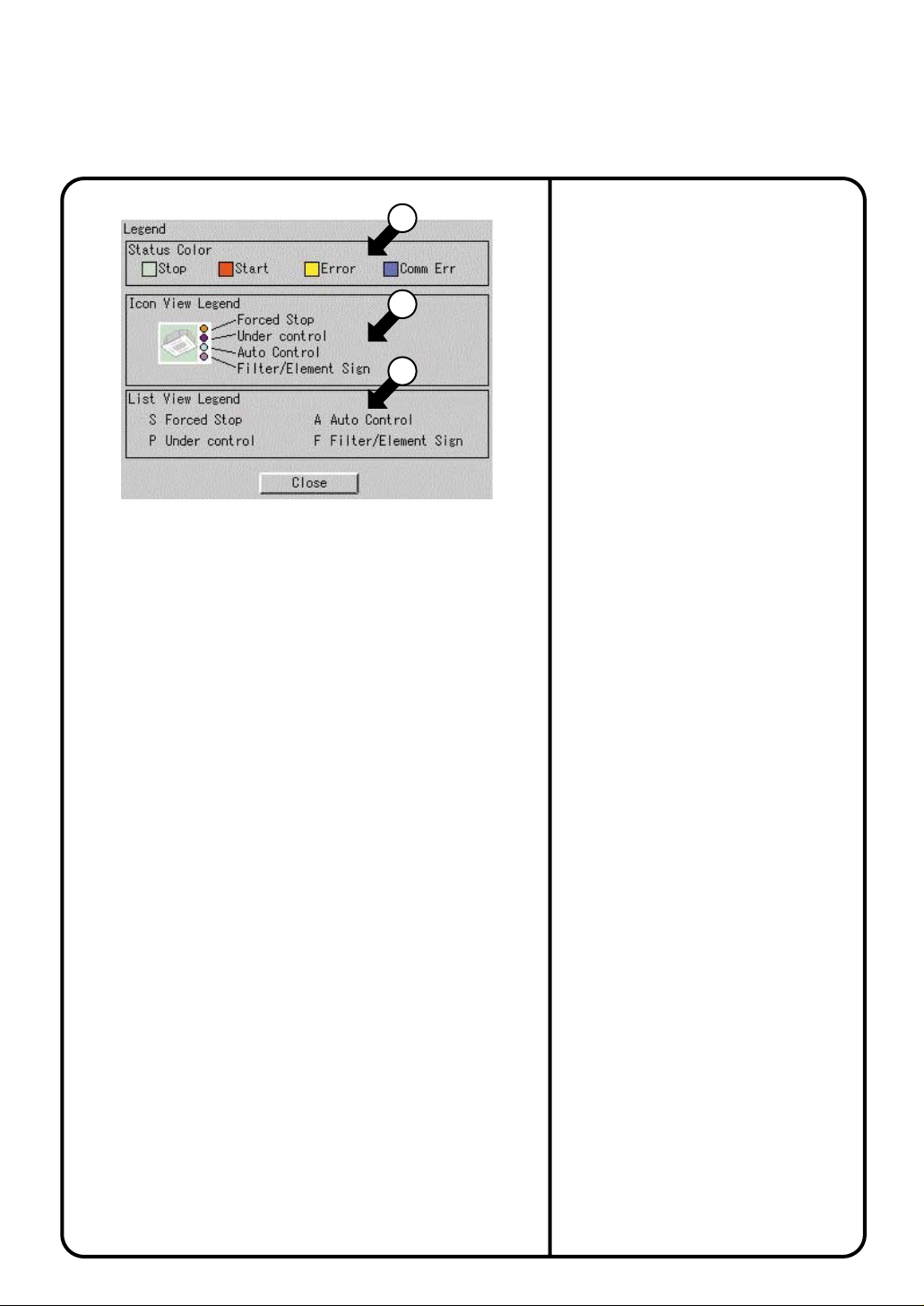
Monitor Zone or Group Operation Status
Screen 4 Legend Description
10
11
12
At o, you can monitor at a glance the
operation status of all air conditioners
connected to the intelligent Touch Controller.
When no problem is found and one or more air
conditioners are operating : Display in red
When no problem is found and air conditioners
are not operating : Display in green
When one or more wrong air conditioners
are found : Display in yellow
When one or more air conditions with
communication errors are found : Display in blue
You may change the colors indicating the
operation active or inactive status through the
use of Icon Color Setting on the System Setting
menu.
See page 34 for Icon color setting.
NOTE: Representative zone
When monitoring takes place in units of groups
on the Monitoring Screen, the following groups
indicate the zone representative machines.
¡
When the display type is icon : Leftmost
group on the top line
¡
When the display type is detailed icon or list:
Groups on the top line.
!0 displays the operation status of an air
conditioner.
For zone list display, display takes place as
shown below.
¡
When no problem is found and one or more air
conditioners are operating : Display in red
¡When no problem is found and no air
conditioner is operating : Display in green
¡When one or more wrong air conditioners
are found : Display in yellow
¡When one or more air conditions with
communication errors are found : Display
in blue
You may change the colors indicating the
operation active or inactive status through the
use of Icon Color Setting on the System
Setting menu.
See page 34 for Icon color setting.
!1
provides for icon or detailed icon display.
!2
provides for list display.
Machines subject to automatic control are
displayed only when schedule settings are
made.
They cannot be displayed when Heating
Mode Optimization or Temperature Limit has
been set.
27
Monitoring Detailed Information
Screen 1 Monitoring (Icon Display)
3
Screen 2 Operation Screen
4
5
6
7
Screen 3 Advanced Settings Screen
10
11
12
15
Monitor Operation Status of a Zone or Group in Detail
When monitoring the operation status in detail,
you may choose any of three
display types, icon, detailed icon and list.
You may monitor the details of the operation
status in units of zones or groups.
1
2
8
9
13
14
Select either Zone or Group by pushing
1.
the button q.
Note that screens in the left-hand
are examples for group selection.
Push [Configure] button w to display the
2.
Operation Screen Screen 2.
When a zone is selected in the above
operation, both r to y on Screen 2 and
!0 to !4 on Screen 3 show the operation
status of the representative machine in
that zone. !55 displays ON so long as at
least one of the filter signs or element
signs is on in the zone or group.
The following describes in order the
contents of display data on Screen 2.
The grayed characters in r to y indicate the
current status of the selected zone or group.
The meanings of screen data in the lefthand column are shown below.
Operation start/stop status : Start
Operation mode setting status: Cool
Setpoint setting status : 75°F
Push [Advanced Settings] button u to display
3.
the Advanced Settings Screen Screen 3.
To return to the Monitoring Screen
Screen 1, push [Cancel] button o.
The following describes in order the contents of display
data on the Advanced Settings Screen Screen 3.
!0 displays the settings made for start and
stop remote control operations.
Prohibited, Stop Only or Permitted is displayed.
!1
displays the settings made for remote control
operations to change the operation mode.
Either Permitted or Prohibited is displayed.
!2 displays the settings for remote control
operations to change the setting
temperature.
Either Permitted or Prohibited is displayed.
!3 displays the current status of the Fan
Speed
!4 displays the direction of wind.
!5 displays a filter sign.
.
A value from 1 to 7 is displayed.
Wind flows more vertically as the setting
value becomes larger in a range from 0 to
6. When the setting value 7 is displayed,
the direction of wind is swung automatically.
Note that these descriptions may vary from
model to model.
Check for a wind direction displayed on the
remote control.
Either ON and OFF is displayed.
column
Operation
16
∗
Display data on Screens 2 and 3 is updated each
time the respective screens are displayed.
Once these screens are displayed, no data is
updated unless they are closed and opened again.
Check the settings and push [Cancel] button !6
4.
.
28
Monitoring Detailed Information
Screen 4 Monitoring Screen (Icon Display)
17
Screen 5 Detailed Information Screen
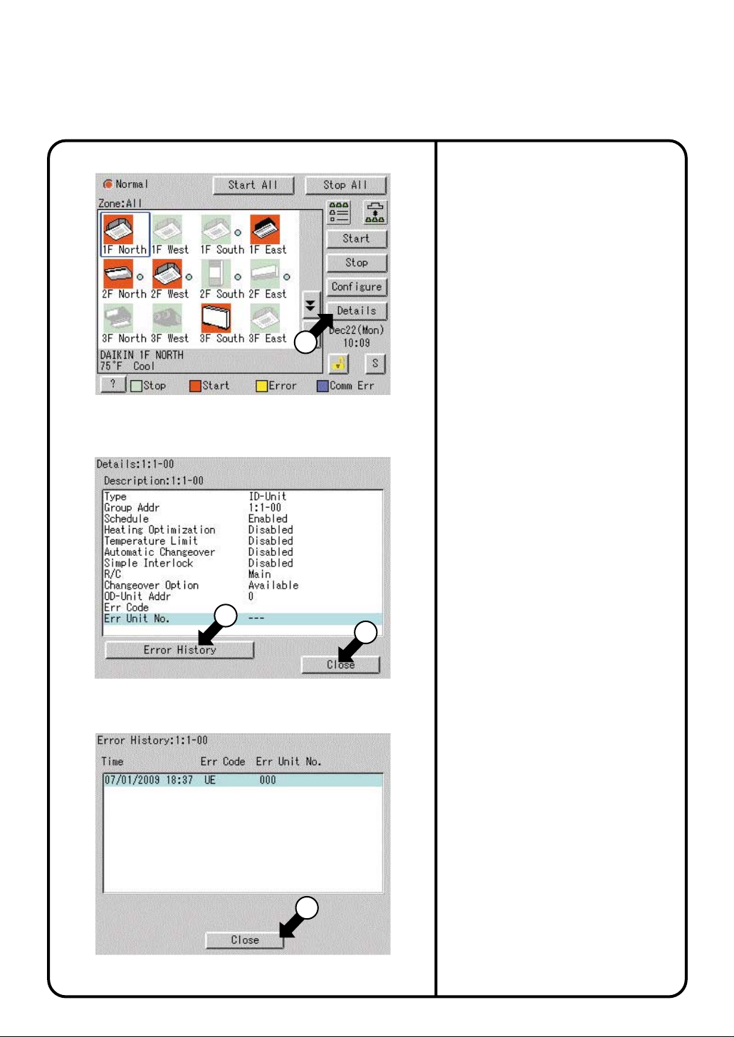
Push [Details] button !7.
5.
The following maintenance data is
displayed on the Detailed Information
Screen Screen 5.
Note that screens in the left-hand
are examples for group selection.
column
[For group selection]
Name : Group name
Detailed name : Detailed group name
Type : ID-Unit / HRV / D3Dio / D3Di
Group Address : 1:1-00 to 1:4-15
When DIII-NET Plus adapter is enabled:
1:1-00 to 2:4-15
Schedule : Enabled or disabled
Heating Optimization : Enabled or disabled
Temperature Limit : Enabled or disabled
Automatic Changeover
R / C : Main or Sub
Changeover Option :
OD-Unit Address : Outside unit address
Err Code : 2-digit error code in
case of error occurence
Err Unit No.
: [–]
for no error or unit number for error
: Enabled or disabled
N/A / Available / Selectable
[For zone selection]
Details : Zone name
Description : Detailed zone name
Sequential Start : Enabled or disabled
No. of Regist Grp : Number of groups registered in a zone
Schedule : Enabled or disabled
Screen 6 Error History
18
20
19
Push [Error history] button !8 to display
6.
the Error History Screen (Screen 6).
The following data is displayed on the Error
History.
[For group selection]
Name : group name
Detailed name : Detailed group name
Error log :
¡Time : Error occurrence time
¡Err Code : 2-digit error code
¡Err Unit No : Unit number
[For zone selection]
Name : group name
Error log :
¡Time : Error occurrence time
¡Name : Error occurrence group name
¡Err Code : 2-digit error code
¡Err Unit No : Unit number
Top 10 error logs are displayed, assigning
the highest priority to the time of the latest
error.
∗ When the same error recurs, the error time
is renewed.
Check for display data and push [Close]
button @0 to return to the detailed
information screen Screen 5. To return to
the Monitoring Screen Screen 4, push
[Close] button !9 on that screen.
29
Loading...