


 Loading...
INSTALLATION MANUAL
R410A Split Series
|
Installation manual |
|
R410A Split series |
|
Installationsanleitung |
|
Split-Baureihe R410A |
|
Manuel d’installation |
|
Série split R410A |
|
Montagehandleiding |
|
R410A Split-systeem |
|
Manual de instalación |
|
Serie Split R410A |
|
Manuale d’installazione |
|
Serie Multiambienti R410A |
Models |
Εγχειρßδιο εγκατÜστασηò |
διαιροýìενηò σειρÜò R410A |
|
4MXS68F2V1B |
4MKS75F2V1B |
3MXS68G2V1B |
Manual de Instalação |
Série split R410A |
|
|
Рóêоводство по монтажó |
|
Серия R410A с раздельной óстановêой |
|
Montaj kýlavuzlarý |
|
R410A Split serisi |
English
Deutsch
Français
Nederlands
Español
Italiano
ΕλληνικÜ
Portugues
Рóссêий
Türkçe

DAIKIN INDUSTRIES, LTD.
4MXS68F2V1B, 4MKS75F2V1B, 3MXS68G2V1B
Low Voltage 2006/95/EC
Electromagnetic Compatibility 2004/108/EC
1D-3SB63850
|
|
|
|
|
|
|
|
|
|
|
|
|
|
|
|
Daikin.TCF.015 |
|
|
|
|
|
|
|
|
|
|
|
|
|
|
|
|
|
|
|
|
|
Daikin.TCF.015 |
|
|
|
|
|
|
|
|
|
|
|
|
|
|
Daikin.TCF.015 |
|
|
|
|
|
|
|
|
|
|
|
74736-KRQ/EMC97-4957. |
|||||||||||||||||||||
|
|
|
|
|
|
74736-KRQ/EMC97-4957. |
|
|
|
|
|
|
|
|
|
|
|
|
|
|
|
|
|
|
74736-KRQ/EMC97-4957. |
|
|
|
|
|
|
|
|
|
|
|
|
|
|
|
|
|
|
|
|
|
|
|
|
|
|
|
|
|
|
|
|
|
|
|
|
|
|
|
|
|
|
|
|
|
||||||||||||||||
|
|
|
|
|
|
|
|
|
|
|
|
|
|
|
|
|
|
|
|
|
|
|
|
|
|
|
|
|
|
|
|
|
|
|
|
|
|
|
|
|
|
|
|
|
|
|
|
|
|
|
|
|
|
|
|
|
|
|
|
|
|
|
|
|
|
|
|
|
|
|
|
|
|
|
|
|
|
|
|
|
|
|||||
|
|
|
|
|
|
|
|
|
|
|
|
|
|
Daikin.TCF.015 |
Daikin.TCF.015 |
|
|
|
|
|
|
|
|
|
|
|
|
|
|
Daikin.TCF.015 |
||||||||||||||||||||||||||||||||||||||||||||||||||||||||
74736-KRQ/EMC97-4957. |
|
|
|
|
|
|
|
|
|
|
|
|
|
|
|
|
|
|
|
|
|
|
|
|
|
|
|
74736-KRQ/EMC97-4957. |
|
|
|
|
|
|
|
|
|
|
|
|
|
|
|
|
|
|
74736-KRQ/EMC97-4957. |
|
|
|
|
|
|
|
|
|
|
|
|
|
|
|||||||||||||||||||||||||
|
|
|
|
|
|
|
|
|
|
|
|
|
|
|
|
|
|
|
|
|
|
|
|
|
|
|
|
|
|
|
|
|
|
|
|
|
|
|
|
|
|
|
|
|
|
|
|
|
|
|
|
|
|
|
|
|
|
|
|
|
|
|
|
|
|
|
|
|
|
|
|
|
|
|
|
|
|
|
|
|
|
|||||
|
|
|
|
|
|
|
|
|
|
|
|
|
|
|
|
|
|
|
|
Daikin.TCF.015 |
Daikin.TCF.015 |
|
|
|
|
|
|
|
|
|
|
|
|
|
|
Daikin.TCF.015 |
||||||||||||||||||||||||||||||||||||||||||||||||||
|
|
|
|
74736-KRQ/EMC97-4957. |
|
|
|
|
|
|
|
|
|
|
|
|
|
|
|
74736-KRQ/EMC97-4957. |
|
|
|
|
|
|
|
|
|
|
|
|
|
|
|
|
|
|
|
|
|
|
74736-KRQ/EMC97-4957. |
|
|
|
|
|
|
|
|
|
|
|
|
|
|
|||||||||||||||||||||||||||||
|
|
|
|
|
|
|
|
|
|
|
|
|
|
|
|
|
|
|
|
|
|
|
|
|
|
|
|
|
|
|
|
|
|
|
|
|
|
|
|
|
|
|
|
|
|
|
|
|
|
|
|
|
|
|
|
|
|
|
|
|
|
|
|
|
|
|
|
|
|
|
|
|
||||||||||||||
|
|
|
|
|
|
|
|
|
|
|
|
|
|
|
|
|
|
Daikin.TCF.015 |
Daikin.TCF.015 |
Daikin.TCF.015 |
||||||||||||||||||||||||||||||||||||||||||||||||||||||||||||||||||
|
74736-KRQ/EMC97-4957. |
|
|
|
|
|
|
|
|
|
|
|
|
|
|
|
|
|
|
|
74736-KRQ/EMC97-4957 |
|
|
|
|
|
|
|
|
|
|
|
|
|
|
|
|
74736-KRQ/EMC97-4957. |
|
|
|
|
|
|
|
|
|
|
|
|
|
|
||||||||||||||||||||||||||||||||||
|
|
|
|
|
|
|
|
|
|
|
|
|
|
|
|
|
|
|
|
|
|
|
|
|
|
|
|
|
|
|
|
|
|
|
|
|
|
|
|
|
|
|
|
|
|
|
|
|
|
|
|
|
|
|
|
|
|
|
|
|
|
|
|
|
|
|
|
|||||||||||||||||||
|
|
|
|
|
|
|
|
|
|
|
|
|
|
|
|
|
|
|
|
|
|
Daikin.TCF.015 |
Daikin.TCF.015 |
Daikin.TCF.015, |
||||||||||||||||||||||||||||||||||||||||||||||||||||||||||||||
|
|
|
|
|
74736-KRQ/EMC97-4957. |
|
|
|
|
|
|
|
|
|
|
|
|
|
|
|
74736-KRQ/EMC97-4957. |
|
|
|
|
|
|
|
|
|
|
|
|
74736-KRQ/EMC97-4957. |
|
|
|
|
|
|
|
|
|
|
|
|
|
|
||||||||||||||||||||||||||||||||||||||
|
|
|
|
|
|
|
|
|
|
|
|
|
|
|
|
|
|
|
|
|
|
|
|
|
|
|
|
|
|
|
|
|
|
|
|
|
|
|
|
|
|
|
|
|
|
|
|
|
|
|
|
|
|
|
|
|
|
|
|
|
|
|
|
|
|
|||||||||||||||||||||
|
|
|
|
|
|
|
|
|
|
Daikin.TCF.015 |
|
Daikin.TCF.015 |
|
|
|
|
|
|
|
|
|
|
|
|
|
|
Daikin.TCF.015 |
|||||||||||||||||||||||||||||||||||||||||||||||||||||||||||
|
|
|
74736-KRQ/EMC97-4957. |
|
|
|
|
|
|
|
|
|
|
|
|
|
74736-KRQ/EMC97-4957. |
|
|
|
|
|
|
|
|
|
|
|
|
74736-KRQ/EMC97-4957. |
|
|
|
|
|
|
|
|
|
|
|
|
|
|||||||||||||||||||||||||||||||||||||||||||
|
|
|
|
|
|
|
|
|
|
|
|
|
|
|
|
|
|
|
|
|
|
|
|
|
|
|
|
|
|
|
|
|
|
|
|
|
|
|
|
|
|
|
|
|
|
|
||||||||||||||||||||||||||||||||||||||||
|
|
|
|
|
|
|
|
|
|
|
|
|
|
|
|
|
|
|
|
|
|
Daikin.TCF.015 |
Daikin.TCF.015 |
Daikin.TCF.015 |
74736-KRQ/EMC97-4957 |
|||||||||||||||||||||||||||||||||||||||||||||||||||||||||||||
|
|
|
|
|
|
74736-KRQ/EMC97-4957. |
|
|
|
|
|
|
|
|
|
74736-KRQ/EMC97-4957 |
|
|
|
|
|
|
|
|
|
|
|
|
|
|
|
|
|
|
|
|
|
|
|
|
|
|
|
|
|
|
|
|
|
|||||||||||||||||||||||||||||||||||||
|
|
|
|
|
|
|
|
|
|
|
|
|
|
|
|
|
|
|
|
|
|
|
|
|
|
|
|
|
|
|
|
|
|
|
|
|
|
|
|
|
|
|
|
|
|
|
|
|
|
|
|
|
|
|
|
|
|
|
|
|
|
|
|
|
|
|
|
|
|
|
|
|
|
|
||||||||||||
|
|
|
|
|
|
|
|
|
|
|
|
|
|
|
|
|
|
|
|
|
Daikin.TCF.015 |
Daikin.TCF.015 |
|
|
|
|
|
|
|
|
|
|
|
|
|
|
|
|
|
|
|
|
|
|
|
|
|
|
||||||||||||||||||||||||||||||||||||||
|
|
74736-KRQ/EMC97-4957. |
|
|
|
|
|
|
|
|
|
|
|
|
|
74736-KRQ/EMC97-4957. |
|
|
|
|
|
|
|
|
|
|
|
|
|
|
|
|
|
|
|
|
|
|
|
|
|
|
|
|
|
|
|
|||||||||||||||||||||||||||||||||||||||
|
|
|
|
|
|
|
|
|
|
|
|
|
|
|
|
|
|
|
|
|
|
|
|
|
|
|
|
|
|
|
|
|
|
|
|
|
|
|
|
|
|
|
|
|
|
|
|
|
|
|
|
|
|
|
|
|
|
|
|
|
|
|
|
|
|
|
|
|
||||||||||||||||||
|
|
|
|
|
|
|
|
|
|
|
|
|
|
|
|
|
Daikin.TCF.015 |
Daikin.TCF.015 |
|
|
|
|
|
|
|
|
|
|
|
|
|
|
|
|
|
|
|
|
|
|
|
|
|
|
||||||||||||||||||||||||||||||||||||||||||
|
|
|
|
|
|
|
74736-KRQ/EMC97-4957. |
|
|
|
|
|
|
|
|
74736-KRQ/EMC97-4957. |
|
|
|
|
|
|
|
|
|
|
|
|
|
|
|
|
|
|
|
|
|
|
|
|
|
|
|
|
|
|||||||||||||||||||||||||||||||||||||||||
Noboru Murata
Manager Quality Control Department
Umeda Center Bldg., 2-4-12, Nakazaki-Nishi,
Shiga, 1st of Oct. 2007
Kita-ku, Osaka, 530-8323 Japan
Safety Precautions
•Read these Safety Precautions carefully to ensure correct installation.
•This manual classifies the precautions into WARNING and CAUTION.
Be sure to follow all the precautions below: they are all important for ensuring safety.
WARNING............... |
Failure to follow any of WARNING is likely to result in such grave consequences as death or serious injury. |
||
CAUTION............... |
Failure to follow any of CAUTION may in some cases result in grave consequences. |
||
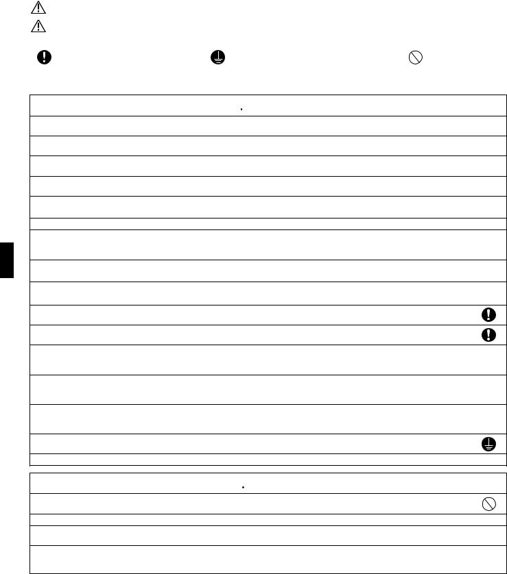
• The following safety symbols are used throughout this manual: |
|
||
|
|
|
|
Be sure to observe this instruction. |
Be sure to establish an earth connection. |
Never attempt. |
|
|
|
|
|
•After completing installation, test the unit to check for installation errors. Give the user adequate instructions concerning the use and cleaning of the unit according to the Operation Manual.
 WARNING
• Installation should be left to the dealer or another professional.
Improper installation may cause water leakage, electrical shock, or fire.
• Install the air conditioner according to the instructions given in this manual.
Incomplete installation may cause water leakage, electrical shock, or fire.
• Be sure to use the supplied or specified installation parts.
Use of other parts may cause the unit to come to lose, water leakage, electrical shock, or fire.
• Install the air conditioner on a solid base that can support the unit’s weight.
An inadequate base or incomplete installation may cause injury in the event the unit falls off the base.
•Electrical work should be carried out in accordance with the installation manual and the national electrical wiring rules or code of practice. Insufficient capacity or incomplete electrical work may cause electrical shock or fire.
•Be sure to use a dedicated power circuit. Never use a power supply shared by another appliance.
•For wiring, use a cable length enough to cover the entire distance with no connection.
Do not use an extension cord. Do not put other loads on the power supply, use a dedicated power circuit.
(Failure to do so may cause abnormal heat, electric shock or fire.)
• Use the specified types of wires for electrical connections between the indoor and outdoor units. Firmly clamp the interconnecting wires so their terminals receive no external stresses. Incomplete connections or clamping may cause terminal overheating or fire.
•After connecting interconnecting and supply wiring be sure to shape the cables so that they do not put undue force on the electrical covers or panels. Install covers over the wires. Incomplete cover installation may cause terminal overheating, electrical shock, or fire.
•If any refrigerant has leaked out during the installation work, ventilate the room.
(The refrigerant produces a toxic gas if exposed to flames.)
• After all installation is complete, check to make sure that no refrigerant is leaking out.
(The refrigerant produces a toxic gas if exposed to flames.)
• When installing or relocating the system, be sure to keep the refrigerant circuit free from substances other than the specified refrigerant (R410A), such as air.
(Any presence of air or other foreign substance in the refrigerant circuit causes an abnormal pressure rise or rupture, resulting in injury.)
• During pump-down, stop the compressor before removing the refrigerant piping.
If the compressor is still running and the stop valve is open during pump-down, air will be sucked in when the refrigerant piping is removed, causing abnormal pressure in the freezer cycle which will lead to breakage and even injury.
• During installation, attach the refrigerant piping securely before running the compressor.
If the compressor is not attached and the stop valve is open during pump-down, air will be sucked in when the compressor is run, causing abnormal pressure in the freezer cycle which will lead to breakage and even injury.
• Be sure to establish an earth. Do not earth the unit to a utility pipe, arrester, or telephone earth.
Incomplete earth may cause electrical shock, or fire. A high surge current from lightning or other sources may cause damage to the air conditioner.
• Be sure to install an earth leakage breaker. Failure to install an earth leakage breaker may result in electric shocks, or fire.
 CAUTION
• Do not install the air conditioner in a place where there is danger of exposure to inflammable gas leakage.
If the gas leaks and builds up around the unit, it may catch fire.
•Establish drain piping according to the instructions of this manual. Inadequate piping may cause flooding.
•Tighten the flare nut according to the specified method such as with a torque wrench.
If the flare nut is tightened too hard, the flare nut may crack after a long time and cause refrigerant leakage.
• Make sure to provide for adequate measures in order to prevent that the outdoor unit be used as a shelter by small animals.
Small animals making contact with electrical parts can cause malfunctions, smoke or fire. Please instruct the customer to keep the area around the unit clean.
1 |
■English |
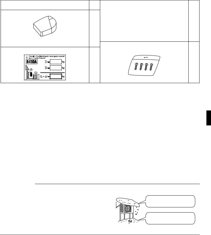
Accessories
Accessories supplied with the outdoor unit:
(A) Installation Manual |
1 |
(B) Drain plug |
(C) Reducer assy |
|
|
|
|
1 |
|
1 |
|
There is on the bottom packing case. |
|
There is on the bottom packing case. |
|
|
|
(4MXS68*, 4MKS75*) |
|
(D) Screw bag |
|
|
|
(E) Refrigerant charge label |
|
(For fixing electrical wire anchor bands) |
|
|
|
|
1 |
1 |
|
|
|
|
|
There is on the bottom packing case. |
Precautions for Selecting the Location
1)Choose a place solid enough to bear the weight and vibration of the unit, where the operation noise will not be amplified.
2)Choose a location where the hot air discharged from the unit or the operation noise, will not cause a nuisance to the neighbors of the user.
3)Avoid places near a bedroom and the like, so that the operation noise will cause no trouble.
4)There must be sufficient spaces for carrying the unit into and out of the site.
5)There must be sufficient space for air passage and no obstructions around the air inlet and the air outlet.
6)The site must be free from the possibility of flammable gas leakage in a nearby place. Locate the unit so that the noise and the discharged hot air will not annoy the neighbors.
7)Install units, power cords and inter-unit cables at least 3 meter away from television and radio sets. This is to prevent interference to images and sounds. (Noises may be heard even if they are more than 3 meter away depending on radio wave conditions.)
8)In coastal areas or other places with salty atmosphere of sulfate gas, corrosion may shorten the life of the air conditioner.
9)Since drain flows out of the outdoor unit, do not place under the unit anything which must be kept away from moisture.
NOTE:
Cannot be installed hanging from ceiling or stacked.
 CAUTION
When operating the air conditioner in a low outdoor ambient temperature, be sure to follow the instructions described below.
1)To prevent exposure to wind, install the outdoor unit with its suction side facing the wall.
2)Never install the outdoor unit at a site where the suction side may be exposed directly to wind.
3)To prevent exposure to wind, it is recommended to install a baffle plate on the air discharge side of the outdoor unit.
4)In heavy snowfall areas, select an installation site where the snow will not affect the unit.
 Construct a large canopy.
  Construct a pedestal.
Install the unit high enough off the ground to prevent burying in snow.
■English |
2 |
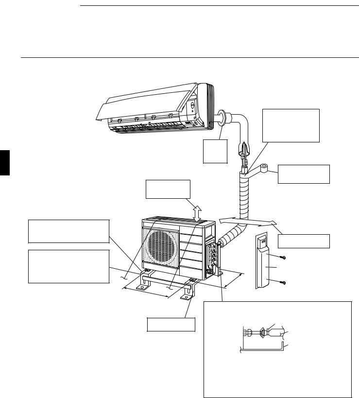
Indoor/Outdoor Unit
Installation Drawings
For installation of the indoor units, refer to the installation manual which was provided with the units. (The diagram shows a wall-mounted indoor unit.)
 CAUTION
1)Do not connect the embedded branch piping and the outdoor unit when only carrying out piping work without connecting the indoor unit in order to add another indoor unit later.
Make sure no dirt or moisture gets into either side of the embedded branch piping. See “7 Refrigerant piping work” on page 8 for details.
2)Heat pump type: It is impossible to connect the indoor unit for one room only. Be sure to connect at least 2 rooms. Cooling only type: It is possible to connect the indoor unit for one room only.
Cut thermal insulation pipe to an appropriate length and wrap it with tape, making sure that no gap is left in the insulation pipe’s cut line.
Caulk pipe hole
gap with putty.
Wrap the insulation pipe with the finishing tape from bottom to top.
Allow 30cm of work space below the ceiling surface.
If there is the danger of the unit falling or overturning, fix the unit with foundation bolts, or with wire or other means.
If the location does not have good drainage, place the unit on a level mounting base (or a plastic pedestal). Install the outdoor unit in a level position. Failure to do so may result in water leakage or accumulation.
(Foot |
58cm |
|
bolt- |
|
hole |
|
centres) |
Level mounting base (available separately)
25cm |
from wall |
|
Allow space for piping and electrical servicing.
Stop valve cover
33cm |
-hole |
|
bolt |
centres) |
|
(Foot |
|
Also insulate the connection on the outdoor unit.
Clamping material
|
Insulation tube |
Tape |
Service lid |
|
Use tape or insulating material on all connections to prevent air from getting in between the copper piping and the insulation tube.
Be sure to do this if the outdoor unit is installed above.
3 |
■English |
Installation
•Install the unit horizontally.
•The unit may be installed directly on a concrete verandah or a solid place if drainage is good.
•If the vibration may possibly be transmitted to the building, use a vibration-proof rubber (field supply).
1. Connections (connection port)
Install the indoor unit according to the table below, which shows the relationship between the class of indoor unit and the corresponding port.
The total indoor unit class that can be connected to this unit:
Heat pump type: |
|
3MXS68 – Up to 11.0kW |
|
|
|
|
|
|
|
|
||||
|
|
|
|
4MXS68 – Up to 11.0kW |
|
|
|
|
|
|
|
|
||
Cooling only type: |
4MKS75 – Up to 13.5kW |
|
|
|
|
|
|
|
|
|||||
|
|
|
|
|
|
|
|
|
|
|
|
|
||
Port |
|
|
|
4MXS68 |
|
|
|
4MKS75 |
|
|
|
3MXS68 |
||
|
|
|
|
|
|
|
|
|
||||||
A |
20 |
, 25 , 35 , 42 |
20 |
, 25 , 35 |
, 42 |
20 |
, 25 , 35 |
, 42 |
||||||
|
|
|
|
|
|
|
|
|
|
|
|
|
|
|
|
|
|
|
|
|
|
|
|
|
# |
# |
# |
|
# |
B |
20 |
, 25 , 35 , 42 |
20 |
, 25 , 35 |
, 42 |
20 |
, 25 , 35 |
, 42 , 50 |
||||||
|
|
|
|
|
|
|
|
|
|
|
|
|
|
|
|
# |
# |
# |
# |
# |
# |
# |
|
# |
# |
# |
# |
|
# |
C |
20 |
, 25 , 35 , 42 , 50 |
20 |
, 25 , 35 |
, 42 , 50 , 60 |
20 |
, 25 , 35 |
, 42 , 50 |
||||||
|
|
|
|
|
|
|
|
|
|
|
|
|
|
|
|
# |
# |
# |
# |
▲ |
▲ |
▲ |
|
▲ ■ ■ |
|
|
|
|
|
D |
20 |
, 25 , 35 , 42 , 50 60 |
20 |
, 25 , 35 |
, 42 , 50 , 60 , 71 |
|
|
|
|
|
||||
|
|
|
|
|
|
|
|
|
|
|
|
|
|
|
: Use a reducer to connect pipes.
# : Use No. 2 and 4 reducers ▲ : Use No. 5 and 6 reducers
■: Use No. 1 and 3 reducers
Refer to “How to Use Reducers” on page 10 for information on reducer numbers and their shapes.
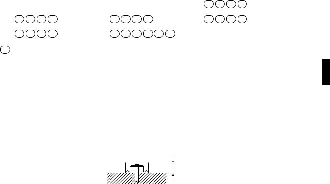
Precautions on Installation
•Check the strength and level of the installation ground so that the unit will not cause any operating vibration or noise after installed.
•In accordance with the foundation drawing in fix the unit securely by means of the foundation bolts. (Prepare four sets of M8 or M10 foundation bolts, nuts and washers each which are available on the market.)
•It is best to screw in the foundation bolts until their length are 20mm from the foundation surface.
20
■English |
4 |
Loading...