


Si-30
Si-30
3 41 2 5 5.2
(US gph)
(Ft)
max. 10 ft (3m)
max. 33 ft (10 m)
5 ft
(1.5m)
5 ft (1.5m)
SAFETY WARNING / AVERTISSEMENTS DE SÉCURITÉ / ADVERTENCIA
Avant toute installation, maintenance ou
EN
Make certain that the entire power supply to the
unit/system is disconnected before attempting to ins-
tall, service or remove any component.
The pump unit must not be immersed in water, installed
outside the premises, stored in a damp environment or
exposed to frost.
All condensate collection elements (collection tray,
connecting tubes, outlets etc…) must be cleaned thoroughly prior to installing the pump.
The pump is supplied with :
- A self-resetting thermal cut-out set at 194°F (90°C).
- A self extinguishing body case (UL94 VO Material)
FR
démontage, mettre impérativement l’ensemble de l’installation hors tension. Le bloc pompe ne doit pas être
immergé, ni placé à l’extérieur des locaux ou dans des
lieux humides et doit être tenu hors gel.
Il est nécessaire de nettoyer les éléments collecteurs de
condensats (bac du climatiseur, tubes, sorties...) av ant l’in stallation de la pompe.
L’ensemble est équipé :
- D’une protection thermique : déclenchement à 194°F
(90°C).
- D’une enveloppe auto-extinguible (matériau
UL94 V0)
Asegúrese de que el suministro total de energía a la
ES
unidad / sistema, esté desconectado antes de intentar
instalar, reparar o quitar cualquier componente.
La bomba no debe ser sumergida en agua, instalada
en el exterior, almacenada en un ambiente húmedo o
expuesta a las heladas.
Todos los elementos de la evacuación de los condensados (bandeja de recogida, los tubos de conexión,
enchufes, etc....) deberán estar bien limpios antes de
instalar la bomba.
La bomba se suministra con:
- Un relé térmico automático ajustado a 194°F (90°C).
- Material auto extinguible al fuego (UL94 VO
Material)
SAUERMANN N.A. Corp.
415 Oser Avenue, Suite P,
Hauppauge, NY 11788/
USA
Tel : (+1) 631-234-7600
Fax : (+1) 631-234-7605
E-mail : sales@sauermann.us
www.sauermannpumps.us
N739- 01 Edition 14/07
KIT CONTENTS / CONTENU DU KIT / CONTENIDO DEL KIT
5ft
D
1.5 m
E
Ø 5/32’’ x 1/4’’ - 2 15/16’’
Ø 4 x 6 mm / 75 mm
A
B
C
G
Ø 19/32’’, 1 49/64’’ x 2 3/8’’
K
H
Ø 15mm, 45x60 mm
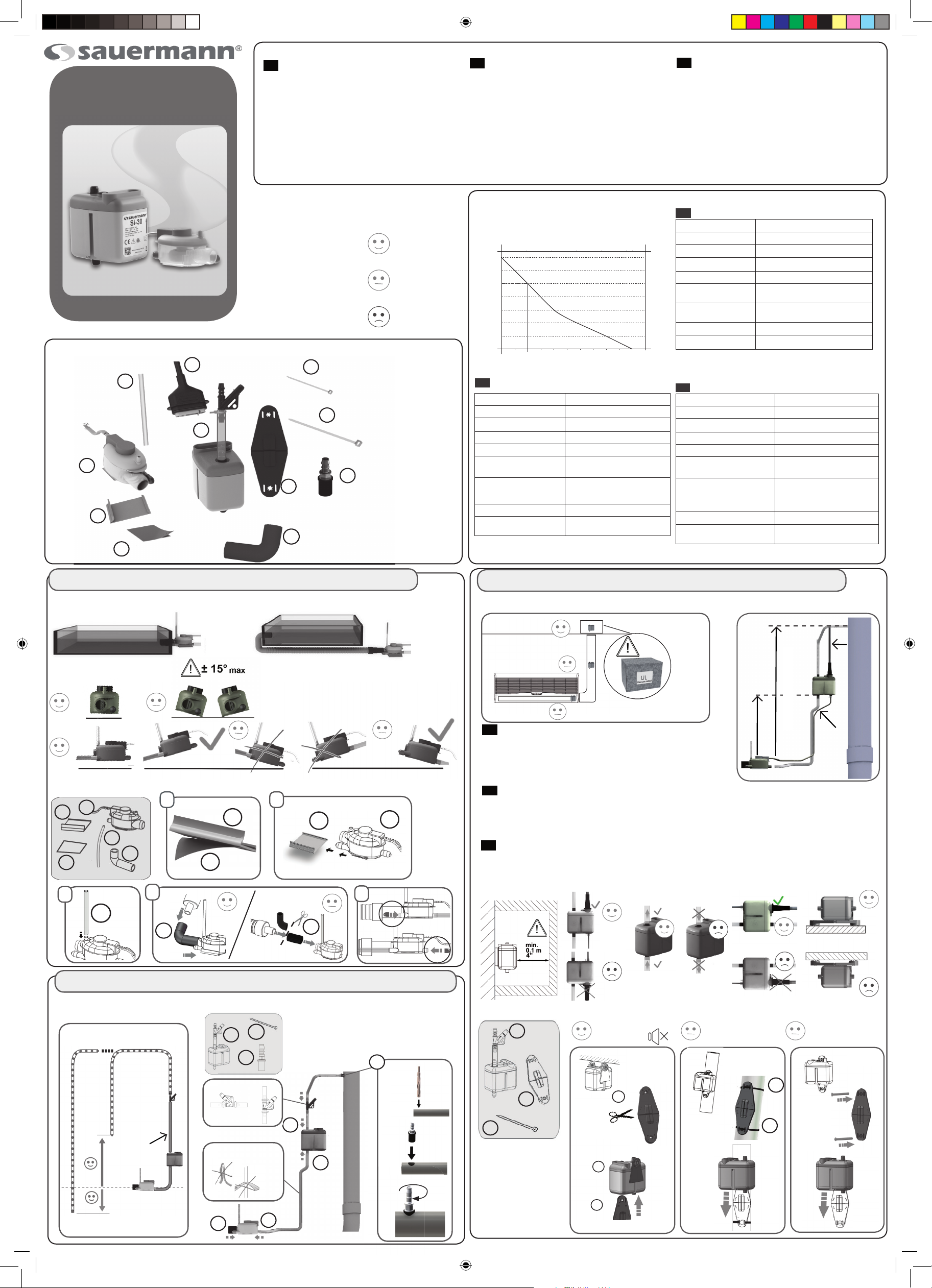
TECHNICAL CHARACTERISTICS /
CARACTERISTIQUES TECHNIQUES /
CARACTERÍSTICAS TÉCNICAS
Recommended
Recommandé
Aconsjado
Optional
Autorisé
Autorizado
Prohibited
Déconseillé
Desaconsejado
1/10’’ x 4’’
x 6
I
J
x 2
L
2.5 x 100 mm
1/8’’ x 12’’
3.5 x 300 mm
Ø1/4’’ (6mm)
14
12
10
8
6
4
2
Hauteur de refoulement (m)
Altura máxima de descarga (m)
0
ES
Caudal máximo 60Hz : 5 gph (19 l/h)
Altura de aspiración máx. 10 ft (3 m)
Altura máx. de descarga 33 ft (10 m)
Tensión 208 - 230V~50/60Hz - 14W
Contacto de alarma NC 8 A resistivo - 250 V
Protección térmica
(sobrecalentamiento)
Niveles de detección On=5/8”Off =7/16’’ Al. =3/4’’
Nivel acústico a 3.3 ft 20 dBA
Normas de seguridad UL/CSA certifi cado por
Capacity (US gph)
2 6 10
4 8 1412 16 18 20
Débit (l/h) - Caudal (l/h)
194°F (90° C)
On:16 mm Off:11 mm Al:19
mm
Intertek
40
32
30
20
Discharge (ft)
10
EN
Max fl ow rate 60Hz : 5 gph (19 l/h)
Max suction head 10 ft (3 m)
Max discharge head 33 ft (10 m)
Voltage 208 - 230V~50/60Hz - 14W
Safety switch NC 8A resistive - 250 V
Thermal protection
(overheating)
Detection levels On=5/8” Off =7/16’’ Al. =3/4’’
Sound level at 3.3 ft 20 dBA
Safety standards UL / CSA certifi ed by Intertek
FR
Débit maximal 60Hz : 5 gph (19 l/h)
Hauteur d’aspiration max. 10 ft (3 m)
Hauteur de refoulement max. 33 ft (10 m)
Alimentation électrique* 208 - 230V~50/60Hz - 14W
Contact de sécurité NF 8 A résistif - 250 V
Protection thermique
(surchauffe)
Niveaux de détection On=5/8”Off =7/16’’
Niveau sonore à 3.3ft 20 dBA
Normes de sécurité
194°F (90° C)
On: 16 mm Off: 11 mm Al: 19 mm
194°F (90° C)
Al. =3/4’’
On:16 mmOff:11 mm Al:19
mm
UL / CSA certifi é par
Intertek
1 | DETECTION UNIT / BLOC DE DETECTION / BLOQUE DE DETECCION 2 | PUMP / POMPE / BOMBA
- Installation overview / Principe d’installation / Esquema de principo
-
- Installation overview / Principe d’installation / Esquema de principo
C
B
- Dos & Dont’s
A
The pump unit can be installed within the air conditioning unit (A),
EN
in an adjacent lineset cover (B) or in the plenum or ceiling space (
- Installation / Instalacion
B
G
E
K
H
3
4
1 2
G
H
G
Do not insulate the pump unit. Use a plenum rated equipment box to protect the
pump (UL 1995).
a bedroom or other sound sensitive area, the preferred installation location of the pump is in
the plenum or ceiling space (C) and not inside the indoor unit (A) nor inside the line set cover (B)
FR
Le bloc pompe peut être fi xé à l’intérieur du climatiseur (A), dans une goulotte adjacente (B), en faux pla f ond, au
de s sus du clim a tis e ur. Ne pas isoler le bloc pompe. Utiliser une boite de protection certifi ée plénum (selon UL 1995) (C).
Remarque : même si le niveau sonore de la pompe est faible, quand l’unité intérieure est installée dans une chambre ou tout
B
5
autre espace sensible au bruit, il est préférable de placer la pompe dans l’entre-plafond (fi gure C) plutôt qu’à l’intérieur de
l’unité (fi gure A) ou dans la goulotte (fi gure B).
ES
El cuerpo bomba se debe fi jar en el climatizador (A), la canaleta (B), o en el falso techo. No se debe aislar el
cuerpo bomba. Utilizar una caja de protección certifi cada plenum (UL 1995) (C). Nota: aunque la bomba tiene un bajo nivel
sonoro, si la unidad interna está instalada en una habitación u otro espacio sensible al ruido, es preferible ubicar la bomba entre el techo y el falso techo
(fi gura C) que en el interior de la unidad (fi gura A) o en la canaleta (fi gura B).
- Dos & Dont’s
Note: Despite a lower operating sound level, if the indoor unit is installed in
C)
.
E
K
K
3 | TUBING CONNECTION / RACCORDEMENT DES TUBES / CONEXIÓN DE LOS TUBOS
- Installation overview / Principe
d’installation / Esquema de principo
min
3ft (1m)
- Installation / Instalacion
x4
I
A
L
OK
Ø 1/4’’ ID
Ø 6 mm ID
I
OK
I
I
L
Ø 3/8’’
(10 mm)
I
- Installation options / Opciones de Instalacion / Modes d’installation
A
C
J
x2
Hung from ceiling
Suspendue
Suspendido
C
A
C
On linesets
Sur un tube
Sobre un tubo
J
J
Wall mounted
Au mur
En la pared
N739_01_1407-DAIKIN.indd 1 17/02/2014 11:34:19
 Loading...