


P/N:TCP520BEF0
Service Manual
COLOR TELEVISION CHASSIS : CP-520
MODEL : DTY-28A8/28A6/28A7 DTY-2880/28W5 DTY-21U7/21B4 DTY-25G6/25G7
CHASSIS : CP-520A
MODEL : DTC-20T2 DTC-21Y1/21Y2
CHASSIS : CP-520F
MODEL : DTZ-29U7/U3 DTZ-2881/28W8 DTZ-2481
Caution
:In this Manual, some parts can be changed for improving. their performance without notice in the parts list. So, if you need the latest parts information, please refer to PPL(Parts Price List)in Service Information Center(http://svc.dwe.co.kr)
DAEWOO ELECTRONICS Corp.
http : //svc.dwe.co.kr |
June. 2004 |
|
|
|
CP-520/520A/520F Service Manual |
|||
|
|
|
CONTENTS |
|
|
|
DOCUMENT HISTORY................................................................................................................. |
3 |
|
||||
1 |
MAIN FEATURES.................................................................................................................. |
4 |
|
|||
|
1.1 |
SPECIFICATIONS.......................................................................................................... |
4 |
|
||
|
1.1.1 |
GENERAL................................................................................................................ |
4 |
|
||
|
1.1.2 EURO-SCART 1 (21 Pin)......................................................................................... |
4 |
|
|||
|
1.1.3 EURO-SCART 2 (21 Pin)......................................................................................... |
5 |
|
|||
|
1.2 |
CHANNEL/FREQUENCY TABLE .................................................................................. |
6 |
|
||
2 |
SAFETY INSTRUCTION ....................................................................................................... |
9 |
|
|||
3 |
ALIGNMENT INSTRUCTIONS............................................................................................ |
10 |
|
|||
|
3.1 |
MICROCONTROLLER CONFIGURATION : SERVICE MODE ................................... |
10 |
|
||
|
3.2 |
SERVICE MODE NAVIGATION ................................................................................... |
10 |
|
||
|
3.3 |
MICROCONTROLLER CONFIGURATION : OPTION BITS........................................ |
10 |
|
||
|
3.4 |
OPTION 1 ..................................................................................................................... |
11 |
|
||
|
3.5 |
OPTION 2 ..................................................................................................................... |
11 |
|
||
|
3.6 |
NVM DEFAULT SETTING............................................................................................ |
12 |
|
||
|
3.7 |
TV SET ALIGNMENT ................................................................................................... |
14 |
|
||
|
3.7.1 |
G2 ALIGNMENT .................................................................................................... |
14 |
|
||
|
3.7.2 |
WHITE BALANCE ................................................................................................. |
14 |
|
||
|
3.7.3 |
FOCUS .................................................................................................................. |
14 |
|
||
|
3.7.4 |
VERTICAL GEOMETRY........................................................................................ |
14 |
|
||
|
3.7.5 |
HORIZONTAL PICTURE CENTRING ................................................................... |
14 |
|
||
|
3.7.6 EAST / WEST CORRECTION ............................................................................... |
14 |
|
|||
|
3.7.7 |
AGC ....................................................................................................................... |
15 |
|
||
4 |
IC DESCRIPTION................................................................................................................ |
16 |
|
|||
|
4.1 |
UOC III SERIES ............................................................................................................. |
16 |
|
||
|
4.1.1 IC MARKING AND VERSION................................................................................ |
16 |
|
|||
|
4.2 |
TDA8946J STEREO AUDIO AMPLIFIER .................................................................... |
24 |
|
||
|
4.2.1 |
FEATURES............................................................................................................ |
25 |
|
||
|
4.3 |
TDA8358J VERTICAL AMPLIFIER ............................................................................. |
27 |
|
||
|
4.3.1 |
TDA8358J.............................................................................................................. |
27 |
|
||
|
4.4 |
TDA6107AJF................................................................................................................ |
29 |
|
||
|
4.4.1 |
Features................................................................................................................. |
29 |
|
||
|
4.4.2 |
Pin description ....................................................................................................... |
29 |
|
||
|
4.5 |
24WC16 - 16 KB EEPROM .......................................................................................... |
30 |
|
||
|
4.6 |
STR - F6653 ................................................................................................................. |
31 |
|
||
|
4.6.1 |
GENERAL DESCRIPTION .................................................................................... |
31 |
|
||
|
4.6.2 |
FEATURES............................................................................................................ |
31 |
|
||
|
4.6.3 |
BLOCK DIAGRAM................................................................................................. |
31 |
|
||
|
4.6.4 |
PIN DESCRIPTION ............................................................................................... |
32 |
|
||
|
4.6.5 |
CONTROL PART - ELECTRICAL CHARACTERISTICS....................................... |
32 |
|
||
|
4.6.6 |
MOSFET ELECTRICAL CHARACTERISTICS ...................................................... |
33 |
|
||
5 |
CIRCUIT DESCRIPTION ..................................................................................................... |
34 |
|
|||
|
5.1 |
BLOCK DIAGRAM ....................................................................................................... |
34 |
|
||
|
5.2 |
FUNCTIONAL DESCRIPTION OF VIDEO PROCESSOR ........................................... |
35 |
|
||
|
5.2.1 |
Vision IF amplifier .................................................................................................. |
35 |
|
||
|
5.2.2 |
QSS sound circuit .................................................................................................. |
35 |
|
||
|
5.2.3 |
FM demodulator..................................................................................................... |
35 |
|
||
|
5.2.4 Audio input selector and volume contro ................................................................. |
36 |
|
|||
|
|
|
|
|||
DTV R&D Europe |
1 |
|
|
|||

CP-520/520A/520F Service Manual
|
|
5.2.4.1 STEREO AND AV STEREO VERSIONS ........................................................... |
36 |
|
|
|
5.2.4.2 MONO VERSIONS ............................................................................................ |
36 |
|
|
5.2.5 CVBS and Y/C input signal selection ..................................................................... |
36 |
||
|
|
5.2.5.1 ALL VERSIONS ................................................................................................. |
36 |
|
|
5.2.6 |
Synchronisation circuit ........................................................................................... |
37 |
|
|
5.2.7 Horizontal and vertical drive................................................................................... |
38 |
||
|
5.2.8 Chroma, luminance and feature processing .......................................................... |
38 |
||
|
5.2.9 |
Colour decoder ...................................................................................................... |
39 |
|
|
5.2.10 |
RGB output circuit.................................................................................................. |
40 |
|
|
5.2.11 I2C-BUS USER INTERFACE DESCRIPTION ....................................................... |
42 |
||
|
5.3 |
GENERAL DESCRIPTION OF THE TV SOUND OF SOUND PROCESSOR.............. |
42 |
|
|
5.3.1 |
Supported standards ............................................................................................. |
43 |
|
|
5.4 |
FUNCTIONAL DESCRIPTION SOUND PROCESSOR ............................................... |
44 |
|
|
5.4.1 The UOC III TV Sound Concept ............................................................................ |
44 |
||
|
5.4.2 Functional Overview Of the digital controller sound part........................................ |
45 |
||
|
5.4.3 |
Demodulator and decoder ..................................................................................... |
46 |
|
6 |
SERVICE PARTS LIST ....................................................................................................... |
49 |
||
|
6.1 |
DTY-28A8FZF-S........................................................................................................... |
49 |
|
|
6.2 |
DTC-20T2FZS-S........................................................................................................... |
54 |
|
|
6.3 |
DTC-21Y1FZF-S........................................................................................................... |
59 |
|
|
6.4 |
DTZ-29U7FZS-S........................................................................................................... |
64 |
|
7 |
EXPLODED VIEW ............................................................................................................... |
69 |
||
|
7.1 |
DTY-28A8..................................................................................................................... |
69 |
|
|
7.2 |
DTY-2880 ..................................................................................................................... |
70 |
|
|
7.3 |
DTY-21U7..................................................................................................................... |
71 |
|
|
7.4 |
DTC-20T2..................................................................................................................... |
72 |
|
|
7.5 |
DTC-21Y1..................................................................................................................... |
73 |
|
|
7.6 |
DTZ-29U7 ..................................................................................................................... |
74 |
|
|
7.7 |
DTZ-2881...................................................................................................................... |
75 |
|
|
7.8 |
DTZ-2481...................................................................................................................... |
76 |
|
8 |
PRINTED CIRCUIT BOARD................................................................................................ |
77 |
||
|
8.1 |
4859809693(CP-520) ................................................................................................... |
77 |
|
|
8.2 |
4859809893(CP-520A)................................................................................................. |
78 |
|
|
8.3 |
4859809993(CP-520F) ................................................................................................. |
79 |
|
9 |
SCHEMATIC DIAGRAM...................................................................................................... |
80 |
||
|
9.1 |
CP-520.......................................................................................................................... |
80 |
|
|
9.2 |
CP-520A ....................................................................................................................... |
81 |
|
|
9.3 |
CP-520F ....................................................................................................................... |
82 |
|
DTV R&D Europe |
2 |

CP-520/520A/520F Service Manual
DOCUMENT HISTORY
VERSION |
DATE |
COMMENTS |
V1.00 |
12/05/04 |
Creation of document (Author JS KIM) for project CP520 50Hz TV. |
|
|
|
DTV R&D Europe |
3 |

CP-520/520A/520F Service Manual
1 MAIN FEATURES
1.1SPECIFICATIONS
1.1.1 |
GENERAL |
|
|
|
|
|
|||
|
|
|
|
|
|
|
|
|
|
|
|
|
TV standard |
|
|
PAL - SECAM B/G D/K, PAL I/I, SECAM L/L’ |
|
|
|
|
|
|
Colour system |
|
Tuner |
PAL, SECAM |
|
|
|
|
|
|
|
|
AV |
PAL, SECAM, PAL 60, NTSC M, NTSC 4.43 |
|
|
|
|
|
|
Sound system |
|
|
NICAM B/G, I, D/K, L, |
|
|
|
|
|
|
|
|
|
|
FM 2Carrier B/G, D/K |
|
|
|
|
|
Power |
|
|
20”,21” : 49W |
|
|
|
|
|
|
consumption |
|
|
21” (4:3) Flat : 59W |
|
|
|
|
|
|
|
|
|
|
28” (4:3) : 69W |
|
|
|
|
|
|
|
|
|
28”(16:9) : 69W |
|
|
|
|
|
Sound Output |
|
|
20” ~ 24” : 4.5W x 2 (at 60% mod, 10% THD) |
|
|
|
|
|
|
Power |
|
|
25” ~ 29” : 7W x 2 (at 60% mod, 10%THD) |
|
|
|
|
|
|
Speaker |
|
|
20” ~ 24” : 7.5W 8 ohm x 2 |
|
|
|
|
|
|
|
|
|
|
25” ~ 29” : 12W 8 ohm x2 |
|
|
|
|
|
Teletext system |
|
|
10 pages memory FASTEXT (FLOF or TOP) |
|
|
|
|
|
|
Aerial input |
|
|
75 ohm unbalanced |
|
|
|
|
|
|
Channel coverage |
|
|
Off-air channels, S-cable channels and hyperband |
|
|
|
|
|
|
Tuning system |
|
|
frequency synthesiser tuning system |
|
|
|
|
|
|
Visual screen size |
|
|
20” : 48cm |
|
|
|
|
|
|
|
|
|
|
21” : 51cm |
|
|
|
|
|
|
|
|
|
28” : 66cm |
|
|
|
|
|
Channel indication |
|
|
On Screen Display |
|
|
|
|
|
|
Program Selection |
|
|
100 programmes |
|
|
|
|
|
|
Aux. terminal |
|
|
EURO-SCART 1 : Audio / Video In and Out, R/G/B |
|
|
|
|
|
|
|
|
|
|
In, Slow and Fast switching. |
|
|
|
|
|
|
|
|
|
EURO-SCART 2 : Audio / Video In and Out, SVHS |
|
|
|
|
|
|
|
|
|
In. |
|
|
|
|
|
|
|
|
|
AV3 : Audio-Video Jack on front of cabinet. |
|
|
|
|
|
|
|
|
|
Headphone jack (3.5 mm) on front of cabinet |
|
|
|
|
|
|
|
|
|
SVHS3 (option) : Jack on front of cabinet – sound |
|
|
|
|
|
|
|
|
|
input common with AV3. |
|
|
|
|
|
Remote Control |
|
|
R-46G22 |
|
|
|
|
|
|
Unit |
|
|
|
|
|
|
|
1.1.2 EURO-SCART 1 (21 Pin) |
|
|
|
|||||
|
|
|
|
|
|
|
|
||
|
Pin |
|
Signal Description |
|
Matching value |
|
|
||
1 |
|
Audio Output Right |
|
0.5 Vrms, Impedance < 1 kΩ, ( RF 54% Mod ) |
|
|
|||
2 |
|
Audio Input Right |
|
0.5 Vrms, Impedance > 10 kΩ |
|
|
|||
3 |
|
Audio Output Left |
|
0.5 Vrms, Impedance < 1 kΩ, ( RF 54% Mod ) |
|
|
|||
4 |
|
Audio Earth |
|
|
|
|
|
||
5 |
|
Blue Earth |
|
|
|
|
|
||
6 |
|
Audio Input Left |
|
0.5 Vrms, Impedance > 10 kΩ |
|
|
|||
7 |
|
Blue Input |
|
0.7 Vpp ±0.1V, Impedance 75Ω |
|
|
|||
|
|
|
|
|
|
|
|
|
|
DTV R&D Europe |
4 |

|
|
|
CP-520/520A/520F Service Manual |
|
|
|
|
|
8 |
Slow Switching |
TV : 0 to 2V, AV 16/9 : 4.5 to 7V, AV 4/3 : 9.5 to 12V , Impedance |
|
|
|
> 10 kΩ |
|
9 |
Green Earth |
|
|
10 |
N.C. |
|
|
11 |
Green Input |
0.7 Vpp ± 0.1V, Impedance 75Ω |
|
12 |
N.C. |
|
|
13 |
Red Earth |
|
|
14 |
Blanking Earth |
|
|
15 |
Red Input |
0.7 Vpp ± 0.1V, Impedance 75Ω |
|
16 |
Fast Switching |
0 to 0.4V : Logic “0”, 1 to 3V : Logic “1”, Impedance 75Ω |
|
17 |
Video Out Earth |
|
|
18 |
Video In Earth |
|
|
19 |
Video Output |
1 Vpp ± 3dB, Impedance 75Ω |
|
20 |
Video Input |
1 Vpp ± 3dB, Impedance 75Ω |
|
21 |
Common Earth |
|
|
1.1.3 EURO-SCART 2 (21 Pin) |
||
|
|
|
|
|
Pin |
Signal Description |
Matching value |
|
1 |
Audio Output Right |
0.5 Vrms, Impedance < 1 kΩ, ( RF 54% Mod ) |
|
2 |
Audio Input Right |
0.5 Vrms, Impedance > 10 kΩ |
|
3 |
Audio Output Left |
0.5 Vrms, Impedance < 1 kΩ, ( RF 54% Mod ) |
|
4 |
Audio Earth |
|
|
5 |
Earth |
|
|
6 |
Audio Input Left |
0.5 Vrms, Impedance > 10 kΩ |
|
7 |
N.C. |
|
|
8 |
N.C. |
|
|
9 |
N.C. |
|
|
10 |
N.C. |
|
|
11 |
N.C. |
|
|
12 |
N.C. |
|
|
13 |
Earth |
|
|
14 |
Earth |
|
|
15 |
Chroma Input |
± 3dB for a luminance signal of 1 Vpp |
|
16 |
N.C. |
|
|
17 |
Earth |
|
|
18 |
Video In Earth |
|
|
19 |
Video Output |
1 Vpp ± 3dB, Impedance 75Ω ( Monitor output ) |
|
20 |
Video Input, Y In. |
1 Vpp ± 3dB, Impedance 75Ω |
|
21 |
Common Earth |
|
DTV R&D Europe |
5 |

CP-520/520A/520F Service Manual
1.2CHANNEL/FREQUENCY TABLE
CHANNEL |
EUROPE CCIR |
FRANCE |
GB(IRELAND) |
EAST OIRT |
C01 |
46.25 |
- |
45.75 |
49.75 |
C02 |
48.25 |
55.75 (L') |
53.75 |
59.25 |
C03 |
55.25 |
60.5 (L') |
61.75 |
77.25 |
C04 |
62.25 |
63.75 (L') |
175.25 |
85.25 |
C05 |
175.25 |
176.00 |
183.25 |
93.25 |
C06 |
182.25 |
184.00 |
191.25 |
175.25 |
C07 |
189.25 |
192.00 |
199.25 |
183.25 |
C08 |
196.25 |
200.00 |
207.25 |
191.25 |
C09 |
203.25 |
208.00 |
215.25 |
199.25 |
C10 |
210.25 |
216.00 |
223.25 |
207.25 |
C11 |
217.25 |
189.25 (LUX) |
231.25 |
215.25 |
C12 |
224.25 |
69.25 (L') |
239.25 |
223.25 |
C13 |
53.75 |
76.25 (L') |
247.25 |
- |
C14 |
- |
83.25 (L') |
49.75 |
- |
C15 |
82.25 |
90.25 |
57.75 |
- |
C16 |
- |
97.25 |
65.75 |
- |
C17 |
183.75 |
- |
77.75 |
- |
C18 |
192.25 |
- |
85.75 |
- |
C19 |
201.25 |
- |
- |
- |
C20 |
- |
- |
- |
- |
C21 |
471.25 |
471.25 |
471.25 |
471.25 |
C22 |
479.25 |
479.25 |
479.25 |
479.25 |
C23 |
487.25 |
487.25 |
487.25 |
487.25 |
C24 |
495.25 |
495.25 |
495.25 |
495.25 |
C25 |
503.25 |
503.25 |
503.25 |
503.25 |
C26 |
511.25 |
511.25 |
511.25 |
511.25 |
C27 |
519.25 |
519.25 |
519.25 |
519.25 |
C28 |
527.25 |
527.25 |
527.25 |
527.25 |
C29 |
535.25 |
535.25 |
535.25 |
535.25 |
C30 |
543.25 |
543.25 |
543.25 |
543.25 |
C31 |
551.25 |
551.25 |
551.25 |
551.25 |
C32 |
559.25 |
559.25 |
559.25 |
559.25 |
C33 |
567.25 |
567.25 |
567.25 |
567.25 |
C34 |
575.25 |
575.25 |
575.25 |
575.25 |
C35 |
583.25 |
583.25 |
583.25 |
583.25 |
C36 |
591.25 |
591.25 |
591.25 |
591.25 |
C37 |
599.25 |
599.25 |
599.25 |
599.25 |
C38 |
607.25 |
607.25 |
607.25 |
607.25 |
C39 |
615.25 |
615.25 |
615.25 |
615.25 |
C40 |
623.25 |
623.25 |
623.25 |
623.25 |
C41 |
631.25 |
631.25 |
631.25 |
631.25 |
C42 |
639.25 |
639.25 |
639.25 |
639.25 |
C43 |
647.25 |
647.25 |
647.25 |
647.25 |
C44 |
655.25 |
655.25 |
655.25 |
655.25 |
C45 |
663.25 |
663.25 |
663.25 |
663.25 |
DTV R&D Europe |
6 |

CP-520/520A/520F Service Manual
C46 |
671.25 |
671.25 |
671.25 |
671.25 |
C47 |
679.25 |
679.25 |
679.25 |
679.25 |
C48 |
687.25 |
687.25 |
687.25 |
687.25 |
C49 |
695.25 |
695.25 |
695.25 |
695.25 |
C50 |
703.25 |
703.25 |
703.25 |
703.25 |
C51 |
711.25 |
711.25 |
711.25 |
711.25 |
C52 |
719.25 |
719.25 |
719.25 |
719.25 |
C53 |
727.25 |
727.25 |
727.25 |
727.25 |
C54 |
735.25 |
735.25 |
735.25 |
735.25 |
C55 |
743.25 |
743.25 |
743.25 |
743.25 |
C56 |
751.25 |
751.25 |
751.25 |
751.25 |
C57 |
759.25 |
759.25 |
759.25 |
759.25 |
C58 |
767.25 |
767.25 |
767.25 |
767.25 |
C59 |
775.25 |
775.25 |
775.25 |
775.25 |
C60 |
783.25 |
783.25 |
783.25 |
783.25 |
C61 |
791.25 |
791.25 |
791.25 |
791.25 |
C62 |
799.25 |
799.25 |
799.25 |
799.25 |
C63 |
807.25 |
807.25 |
807.25 |
807.25 |
C64 |
815.25 |
815.25 |
815.25 |
815.25 |
C65 |
823.25 |
823.25 |
823.25 |
823.25 |
C66 |
831.25 |
831.25 |
831.25 |
831.25 |
C67 |
839.25 |
839.25 |
839.25 |
839.25 |
C68 |
847.25 |
847.25 |
847.25 |
847.25 |
C69 |
855.25 |
855.25 |
855.25 |
855.25 |
C70 |
863.25 |
863.25 |
863.25 |
863.25 |
C71 |
69.25 |
- |
- |
- |
C72 |
76.25 |
- |
- |
- |
C73 |
83.25 |
- |
- |
- |
C74 |
90.25 |
- |
- |
- |
C75 |
97.25 |
- |
- |
- |
C76 |
59.25 |
- |
- |
- |
C77 |
93.25 |
- |
- |
- |
S01 |
105.25 |
104.75 |
103.25 |
105.25 |
S02 |
112.25 |
116.75 |
111.25 |
112.25 |
S03 |
119.25 |
128.75 |
119.25 |
119.25 |
S04 |
126.25 |
140.75 |
127.25 |
126.25 |
S05 |
133.25 |
152.75 |
135.25 |
133.25 |
S06 |
140.25 |
164.75 |
143.25 |
140.25 |
S07 |
147.25 |
176.75 |
151.25 |
147.25 |
S08 |
154.25 |
188.75 |
159.25 |
154.25 |
S09 |
161.25 |
200.75 |
167.25 |
161.25 |
S10 |
168.25 |
212.75 |
- |
168.25 |
S11 |
231.25 |
224.75 |
- |
231.25 |
S12 |
238.25 |
236.75 |
- |
238.25 |
S13 |
245.25 |
248.75 |
255.25 |
245.25 |
S14 |
252.25 |
260.75 |
263.25 |
252.25 |
S15 |
259.25 |
272.75 |
271.25 |
259.25 |
S16 |
266.25 |
284.75 |
279.25 |
266.25 |
S17 |
273.25 |
296.75 |
287.25 |
273.25 |
DTV R&D Europe |
7 |

CP-520/520A/520F Service Manual
S18 |
280.25 |
136.00 |
295.25 |
280.25 |
S19 |
287.25 |
160.00 |
303.25 |
287.25 |
S20 |
294.25 |
- |
- |
294.25 |
S21 |
303.25 |
303.25 |
- |
303.25 |
S22 |
311.25 |
311.25 |
311.25 |
311.25 |
S23 |
319.25 |
319.25 |
319.25 |
319.25 |
S24 |
327.25 |
327.25 |
327.25 |
327.25 |
S25 |
335.25 |
335.25 |
335.25 |
335.25 |
S26 |
343.25 |
343.25 |
343.25 |
343.25 |
S27 |
351.25 |
351.25 |
351.25 |
351.25 |
S28 |
359.25 |
359.25 |
359.25 |
359.25 |
S29 |
367.25 |
367.25 |
367.25 |
367.25 |
S30 |
375.25 |
375.25 |
375.25 |
375.25 |
S31 |
383.25 |
383.25 |
383.25 |
383.25 |
S32 |
391.25 |
391.25 |
391.25 |
391.25 |
S33 |
399.25 |
399.25 |
399.25 |
399.25 |
S34 |
407.25 |
407.25 |
407.25 |
407.25 |
S35 |
415.25 |
415.25 |
415.25 |
415.25 |
S36 |
423.25 |
423.25 |
423.25 |
423.25 |
S37 |
431.25 |
431.25 |
431.25 |
431.25 |
S38 |
439.25 |
439.25 |
439.25 |
439.25 |
S39 |
447.25 |
447.25 |
447.25 |
447.25 |
S40 |
455.25 |
455.25 |
455.25 |
455.25 |
S41 |
463.25 |
463.25 |
463.25 |
463.25 |
DTV R&D Europe |
8 |

CP-520/520A/520F Service Manual
3 ALIGNMENT INSTRUCTIONS
3.1MICROCONTROLLER CONFIGURATION : SERVICE MODE
To switch the TV set into service mode please see instruction below.
1 - Select PR. number 91
2 - Adjust sharpness to minimum and exit all menus.
3 – Within 2 seconds press the key sequence : RED - GREEN - menu
The software version is displayed beside the word Service, e.g. “SERVICE VER 00.05”.
To exit SERVICE menu press menu key or Std By key.
3.2SERVICE MODE NAVIGATION
Pr Up/Down remote keys |
: cycle through the service items available. |
|||||
Vol -/+ remote keys |
: Dec./Increment the values within range – Cycle trough option bits. |
|||||
OK key |
: Toggle bits in option byte |
|
|
|||
|
|
|
|
|
|
|
|
Order |
Item |
|
Default setting |
|
|
|
1 |
|
HOR CEN |
|
|
|
|
2 |
|
RED GAIN |
|
|
|
|
3 |
|
GRN GAIN |
|
|
|
|
4 |
|
BLUE GAIN |
|
|
|
|
5 |
|
RED BIAS |
|
|
|
|
6 |
|
GRN BIAS |
|
|
|
|
7 |
|
AGC LEVEL |
|
|
|
|
8 |
|
G2 – SCREEN |
|
|
|
|
9 |
|
OPTION1 |
|
|
|
|
10 |
|
OPTION2 |
|
|
|
|
11 |
|
AVL |
|
|
|
|
12 |
|
PARABOLA |
|
|
|
|
13 |
|
HOR WIDTH |
|
|
|
|
14 |
|
CORNER T |
|
|
|
|
15 |
|
CORNER B |
|
|
|
|
16 |
|
HOR. PARAL |
|
|
|
|
17 |
|
V. LINEAR |
|
|
|
|
18 |
|
V. SLOPE |
|
|
|
|
19 |
|
EW TRAPEZ |
|
|
|
|
20 |
|
S CORRECT |
|
|
|
|
21 |
|
VERT CENT |
|
|
|
|
22 |
|
VERT SIZE |
|
|
|
3.3MICROCONTROLLER CONFIGURATION : OPTION BITS
There are two option bytes available (16 bits in all). These option bits are available from Service mode. First find the OPTION1 or OPTION2 control, and then use the Volume PLUS/MINUS buttons on the remote control keypad to locate the bits, and OK key to toggle them. The table below shows the two option bytes available;
DTV R&D Europe |
10 |
CP-520/520A/520F Service Manual
3.4OPTION 1
|
B7 |
B6 |
B5 |
B4 |
B3 |
B2 |
B1 |
B0 |
|
|
TOP |
FASTEXT |
TUBE |
VAI bit set |
Dolby |
SVHS3 |
TUNER OPTIONS |
||
1 |
Teletext |
(FLOF) |
to 1 in |
Virtual |
|||||
4:3 |
disable |
00 = Philips |
|||||||
|
OFF |
OFF |
SECAM L |
OFF |
|||||
|
|
|
01 = Not used |
||||||
|
TOP |
|
|
VAI bit set |
Dolby |
|
|||
|
FASTEXT |
TUBE |
SVHS3 |
10 = Alps |
|||||
0 |
Teletext |
to 0 in |
Virtual |
||||||
(FLOF) ON |
16:9 |
enable |
11 = Parstnic (DW) |
||||||
|
ON |
SECAM L |
ON |
||||||
|
|
|
|
|
|
||||
3.5OPTION 2
|
|
B7 |
|
B6 |
B5 |
|
|
B4 |
|
B3 |
|
B2 |
B1 |
B0 |
|||||
|
|
|
|
|
JVC |
AVL |
|
PICTURE |
|
5 keys |
|
Full |
Double |
n.u. |
|||||
|
1 |
|
|
|
remote |
control |
|
|
lacal |
|
ATSS |
Window |
Must |
||||||
|
|
|
|
|
TILT ON |
|
|
||||||||||||
|
|
Fixed to |
control |
OFF |
|
|
keyboard |
|
|
Enabled |
be set |
||||||||
|
|
|
|
|
|
|
|
|
|||||||||||
|
|
|
|
|
|
|
|
|
|
|
|
|
|
|
|
to 1 for |
|||
|
|
‘0’ |
|
Daewoo |
AVL |
|
|
|
|
|
7 keys |
|
|
Double |
|||||
|
|
|
|
PICTURE |
|
|
Basic |
future |
|||||||||||
|
0 |
|
|
|
Remote |
control |
|
|
lacal |
|
Window |
||||||||
|
|
|
|
|
TILT OFF |
|
|
ATSS |
compa |
||||||||||
|
|
|
|
|
control |
ON |
|
|
keyboard |
|
Disabled |
||||||||
|
|
|
|
|
|
|
|
|
|
|
|
tibility |
|||||||
|
|
|
|
|
|
|
|
|
|
|
|
|
|
|
|
|
|
|
|
OPTION SETTING BY MODEL |
|
|
|
|
|
|
|
|
|
|
|
||||||||
|
|
|
|
|
|
|
|
|
|
|
|
|
|
|
|
|
|
||
CHASSIS |
|
|
MODEL |
|
|
|
OPTION |
|
DW[hex] |
|
REMARKS |
|
|
||||||
|
|
|
|
|
BIT[b7…b0] |
|
|
|
|
||||||||||
|
|
|
|
|
|
|
|
|
|
|
|
|
|
|
|
||||
|
|
|
|
DTY-28A6/A7/A8 |
I |
|
0011 |
|
1100 |
|
3C |
|
OPTION1 “b1,b0” - |
|
|
||||
|
|
|
|
|
|
|
II |
|
0000 |
|
1001 |
|
09 |
|
depends on Tuner |
|
|
||
CP-520 |
|
|
|
|
I |
|
0001 |
|
1100 |
|
1C |
|
OPTION2 “b1” – |
|
|
||||
|
DTY-28W5/80 |
|
II |
|
0000 |
|
1001 |
|
09 |
|
From ver. 9.3B |
|
|
||||||
|
|
|
|
|
|
|
|
|
|
|
Change to “1” - *1 |
|
|
||||||
|
|
|
|
|
|
|
|
|
|
|
|
|
|
|
|
|
|
||
|
|
|
|
DTY-21U7 |
|
I |
|
0011 |
|
1100 |
|
3C |
|
|
|
|
|
||
|
|
|
|
|
II |
|
0000 |
|
1001 |
|
09 |
|
|
|
|
|
|||
|
|
|
|
|
|
|
|
|
|
|
|
|
|
|
|||||
CP-520A |
|
DTC-20T2 |
|
I |
|
0011 |
|
1100 |
|
3C |
|
|
|
|
|
||||
|
DTC-21Y1/Y2 |
|
II |
|
0000 |
|
1001 |
|
09 |
|
|
|
|
|
|||||
|
|
|
|
|
|
|
|
|
|
|
|
|
|||||||
|
|
|
|
|
|
|
I |
|
0001 |
|
1000 |
|
18 |
|
If Sales Team |
|
|
||
|
|
|
|
DTZ-2881/W8 |
|
|
|
|
|
|
|
|
|
|
Request TILT |
|
|
||
|
|
|
|
|
|
|
|
|
|
|
|
|
|
function |
|
|
|
||
|
|
|
|
DTZ-2481 |
|
II |
|
0000 |
|
1001 |
|
09 |
|
|
|
|
|||
CP-520F |
|
|
|
|
|
|
Change to OP 2 – |
|
|
||||||||||
|
|
|
|
|
|
|
|
|
|
|
|
|
|
|
|||||
|
|
|
|
|
|
|
|
|
|
|
|
|
|
|
|
“b4” to “1” & *1 |
|
|
|
|
|
|
|
DTZ-29U7/B3 |
|
I |
|
0011 |
|
1000 |
|
38 |
|
|
|
|
|
||
|
|
|
|
|
II |
|
0000 |
|
1001 |
|
09 |
|
|
|
|
|
|||
|
|
|
|
|
|
|
|
|
|
|
|
|
|
|
|||||
DTV R&D Europe |
11 |

CP-520/520A/520F Service Manual
3.6NVM default setting
The purpose of this message, when you change a virgin EEPROM, is to allow to modify the NVM DATA to desired values.
1 - Introduction :
The NVM default valus are fixed for the user, but for flexibility in service, these data are stored in NVM and can be changed when the TV set is in a special mode call "NVM EDITOR". This mode can only be access from "FACTORY" mode.
2 - Entering into "FACTORY" mode.
To switch the TV set into FACTORY mode, use the factory remote control, and press on “SVC” key. The factory menu will appear on the screen, showing “FACTORY” , plus other relevant information like software version and date.
WARNING : When in "FACTORY" mode you should not press any key other than the keys described in the procedure below. Unwanted key stroke could misadjust the TV set.
3 - Entering into "NVM EDITOR" mode.
To switch the TV set into NVM EDITOR mode, use the user remote control, and press on
“PICTURE/OK” key. The NVM EDITOR window will appear on the screen. This mode allow you to access all data stored in NVM. The current NVM address is given in column "ADDR." in both
DECimal and HEXadecimal format. The column DATA gives the value contained at selected address in both DECimal and HEXadecimal format.
4 - Navigation in "NVM EDITOR" mode.
Use Program Up/Dwn keys to select the desired address. Use Volume Up/Dwn keys to change the data at selected address. You must press "PICTURE/OK" key to store value after modification.
The data can be adjusted between 0 and 63.
5 - Exit "NVM EDITOR" mode.
To switch the TV set back into FACTORY mode, use the user remote control, and press on “MENU” key.
The factory menu will appear on the screen, showing “FACTORY”.
6 - Exit "FACTORY" mode.
To exit "FACTORY" mode, use the factory remote control, and press on “SVC” key.
The factory menu will disappear from the screen.
DTV R&D Europe |
12 |

CP-520/520A/520F Service Manual
NVM DATA CHANGE LIST |
|
(hex) |
|
CP-520 |
|
CP-520F |
CP-520A |
||||
No |
Register Name |
Address |
Default |
28A8 |
2880 |
|
21U7 |
2881 |
29U7 |
21Y1 |
20T2 |
1 |
OCP_THRESHOLD |
0x58F |
0x91 |
<- |
<- |
|
<- |
<- |
<- |
<- |
<- |
2 |
DCXO |
0x590 |
0x4E |
<- |
<- |
|
<- |
<- |
<- |
<- |
<- |
3 |
AGC_PHILIPS |
0x5C1 |
0xAB |
<- |
<- |
|
<- |
<- |
<- |
<- |
<- |
4 |
AGC_NC |
0x5C2 |
0xAB |
<- |
<- |
|
<- |
<- |
<- |
<- |
<- |
5 |
AGC_ALPS |
0x5C3 |
0xB6 |
<- |
<- |
|
<- |
<- |
<- |
<- |
<- |
6 |
AGC_PARTSNIC |
0x5C4 |
0xB6 |
<- |
<- |
|
<- |
<- |
<- |
<- |
<- |
7 |
AGC_PHILIPS_START |
0x5C5 |
0x16 |
<- |
<- |
|
<- |
<- |
<- |
<- |
<- |
8 |
AGC_NC_START |
0x5C6 |
0x16 |
<- |
<- |
|
<- |
<- |
<- |
<- |
<- |
9 |
AGC_ALPS_START |
0x5C7 |
0x16 |
<- |
<- |
|
<- |
<- |
<- |
<- |
<- |
10 |
AGC_PARTSNIC_START |
0x5C8 |
0x16 |
<- |
<- |
|
<- |
<- |
<- |
<- |
<- |
11 |
AVLLEV |
0x621 |
0x5 |
<- |
<- |
|
<- |
<- |
<- |
<- |
<- |
12 |
Nor1_Bright |
0x64A |
0x23 |
<- |
<- |
|
<- |
<- |
<- |
<- |
<- |
13 |
Nor1_contrast |
0x64B |
0x2E |
<- |
<- |
|
<- |
<- |
<- |
<- |
<- |
14 |
Nor1_Colour |
0x64C |
0x1C |
<- |
<- |
|
<- |
<- |
<- |
<- |
<- |
15 |
Nor1_Sharpness |
0x64D |
0x23 |
<- |
<- |
|
<- |
<- |
<- |
<- |
<- |
16 |
Nor1_Tint |
0x64E |
0x20 |
<- |
<- |
|
<- |
<- |
<- |
<- |
<- |
17 |
Nor1_JVC_Bri |
0x64F |
0x2D |
<- |
<- |
|
<- |
<- |
<- |
0x22 |
<- |
18 |
Nor1_JVC_Cont |
0x650 |
0x2A |
<- |
<- |
|
<- |
<- |
<- |
0x2E |
<- |
19 |
Nor1_JVC_Colour |
0x651 |
0x1B |
<- |
<- |
|
<- |
<- |
<- |
0x20 |
<- |
20 |
Nor1_JVC_Sharp |
0x652 |
0x23 |
<- |
<- |
|
<- |
<- |
<- |
<- |
<- |
21 |
Nor2_Bright |
0x653 |
0x28 |
0x23 |
<- |
|
<- |
<- |
<- |
0x22 |
<- |
22 |
Nor2_Contrast |
0x654 |
0x13 |
0x1A |
<- |
|
<- |
<- |
<- |
<- |
<- |
23 |
Nor2_Colour |
0x655 |
0x19 |
0x16 |
<- |
|
<- |
<- |
<- |
<- |
<- |
24 |
Nor2_Sharpness |
0x656 |
0x1B |
<- |
<- |
|
<- |
<- |
<- |
<- |
<- |
25 |
Nor2_Tint |
0x657 |
0x20 |
<- |
<- |
|
<- |
<- |
<- |
<- |
<- |
26 |
PresetGainRGB |
0x673 |
0x2A |
<- |
<- |
|
<- |
<- |
<- |
0x22 |
<- |
27 |
PresetGainRGB |
0x674 |
0x2A |
<- |
<- |
|
<- |
<- |
<- |
0x22 |
<- |
28 |
PresetGainRGB |
0x675 |
0x2A |
<- |
<- |
|
<- |
<- |
<- |
0x22 |
<- |
29 |
Cathode_Drive |
0x67B |
0x1 |
<- |
<- |
|
<- |
<- |
<- |
<- |
<- |
30 |
Y_delay_PAL_BG |
0x686 |
0x5 |
<- |
<- |
|
<- |
<- |
<- |
0x1 |
<- |
31 |
Y_delay_SECAM_BG |
0x687 |
0x8 |
<- |
<- |
|
<- |
<- |
<- |
0x6 |
<- |
32 |
Y_delay_PAL_DK |
0x688 |
0x5 |
<- |
<- |
|
<- |
<- |
<- |
0x0 |
<- |
33 |
Y_delay_SCM_DK |
0x689 |
0x5 |
<- |
<- |
|
<- |
<- |
<- |
0x2 |
<- |
34 |
Y_delay_PAL_I |
0x68A |
0x7 |
<- |
<- |
|
<- |
<- |
<- |
0x1 |
<- |
35 |
Y_delay_SECAM |
0x68B |
0x5 |
<- |
<- |
|
<- |
<- |
<- |
<- |
<- |
36 |
Y_delay_SECAM-L |
0x68C |
0x8 |
<- |
<- |
|
<- |
<- |
<- |
0x6 |
<- |
37 |
Y_delay_AV |
0x68D |
0xA |
<- |
<- |
|
<- |
<- |
<- |
0x2 |
<- |
38 |
G2_Bright |
0x68E |
0x1A |
<- |
<- |
|
0x28 |
0x10 |
0x1A |
0x32 |
<- |
39 |
G2_Contrast |
0x68F |
0x42 |
<- |
<- |
|
0x42 |
0x42 |
0x42 |
0x42 |
<- |
DTV R&D Europe |
13 |
CP-520/520A/520F Service Manual
3.7TV SET ALIGNMENT
3.7.1 G2 ALIGNMENT
- Tune a colour bar pattern.
- Find the “G2 – SCREEN” item in service mode.
- Adjust screen volume (on FBT) to bring the cursor to central position(Green).
3.7.2 WHITE BALANCE
- Select a dark picture and adjust RED BIAS and GRN BIAS to the desired colour temperature.
- Select a bright picture and adjust RED, GRN and BLUE GAIN to the desired colour temperature.
3.7.3 FOCUS
Adjust the Focus volume (on FBT) to have the best resolution on screen.
3.7.4 VERTICAL GEOMETRY
Adjust V. LINEAR (linearity), S CORRECT (S. Correction), VERT SIZE (Vertical amplitude),
VERT CENT (vertical centring) to compensate for vertical distortion.
3.7.5 HORIZONTAL PICTURE CENTRING
Adjust HOR CEN (Horizontal centre) to have the picture in the centre of the screen.
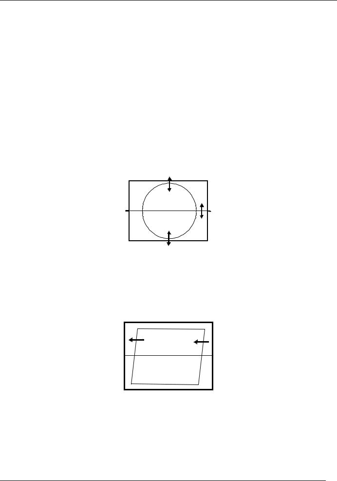
3.7.6 EAST / WEST CORRECTION
Adjust the PARABOLA, HOR WIDTH, CORNER, HOR PARAL, EW TRAPEZ, to compensate for geometrical distortion.
HOR PARAL
DTV R&D Europe |
14 |
CP-520/520A/520F Service Manual
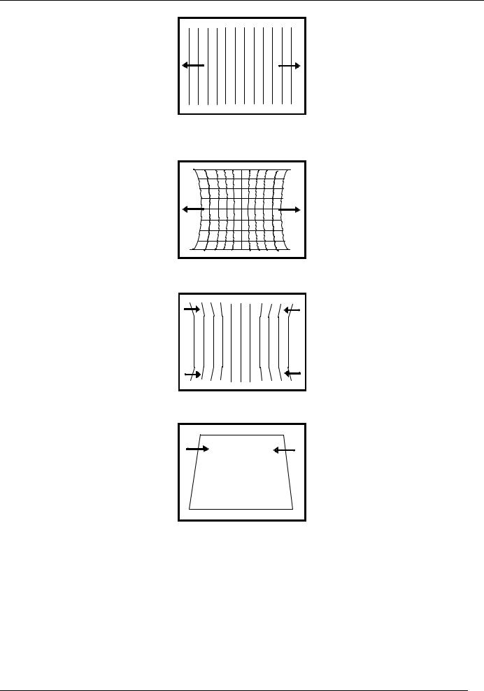
HOR WIDTH adjust for 93% overscan.
PARABOLA |
CORNER B & CORNER T
EW TRAPEZ
3.7.7 AGC
-Make sure option bits are correct for the tuner fitted on the chassis (See above how to change option bits).
-Adjust the antenna signal level at 62 dBμV
-Tune a colour bar pattern.
-Find the “AGC” item in service mode.
-Press the key “OK” on the remote keypad and wait until AGC level stabilise to the optimum value.
-Alternatively, use “Vol Up/Dwn” keys to adjust manually to the desired Tuner Take Over Point
(TOP).
DTV R&D Europe |
15 |

CP-520/520A/520F Service Manual
4 IC DESCRIPTION
4.1UOC III Series
The UOCIII series combines the functions of a Video Signal Processor (VSP) together with a FLASH embedded TEXT/Control/Graphics μ-Controller (TCG μ-Controller) and US Closed Caption decoder. In addition the following functions can be added:
∙Adaptive digital (4H/2H) PAL/NTSC combfilter
∙Teletext decoder with 10 page text memory
∙Multi-standard stereo decoder
∙BTSC stereo decoder
∙Digital sound processing circuit
∙Digital video processing circuit
4.1.1 IC MARKING AND VERSION
Chassis |
IC marking |
OSD languages |
ATSS countries |
Text |
|
|
BULGARIAN, |
Austria, Belgium, |
|
|
|
CZECH, GERMAN, |
|
|
|
|
DANISH, SPANISH, |
Switzerland, Czech |
|
|
|
FRENCH, FINNISH, |
Republic, Germany, |
|
|
|
ENGLISH, GREEK, |
Denmark, Spain, |
|
CP-520A |
|
HUNGARIAN, |
France, Finland, GB, |
PAN-EUROPEAN |
CP-520 |
|
ITALIAN, |
Greece, Hungary, Italy, |
LATIN, CYRILLIC, |
CP-520F |
|
NORWEGIAN, |
Ireland, Norway, |
GREEK. |
|
|
DUTCH, POLISH, |
Netherlands, Portugal, |
|
|
|
ROMANIAN, |
Poland, Sweden, |
|
|
|
RUSSIAN, |
Slovak Republic, |
|
|
|
SWEDISH, |
Others |
|
|
|
SLOVAKIAN. |
|
|
DTV R&D Europe |
16 |

CP-520/520A/520F Service Manual
4.1.2. BLOCK DIAGRAM
DTV R&D Europe |
17 |

|
|
|
|
CP-520/520A/520F Service Manual |
|
4.1.3. PINNING |
|
|
|
|
|
|
|
|
|
QFP 128pin |
|
Symbol |
Short Description |
|
1 |
|
P1.5/TX |
Port 1.5 or UART bus |
|
2 |
|
P1.4/RX |
port 1.4 or UART bus |
|
3 |
|
P1.2/INT2 |
port 1.2 or external interrupt 2 |
|
4 |
|
VSSC3 |
Ground |
|
5 |
|
VDDC3 |
digital supply to core (1.8V) |
|
6 |
|
P2.5/PWM4 |
port 2.5 or PWM4 output |
|
7 |
|
P2.4/PWM3 |
port 2.4 or PWM3 output |
|
8 |
|
VSSC/P |
digital ground for m-Controller core and periphery |
|
9 |
|
P3.3/ADC3 |
port 3.3 or ADC3 input |
|
10 |
|
P3.2/ADC2 |
port 3.2 or ADC2 input |
|
11 |
|
DECV1V8 |
decoupling 1.8 V supply |
|
12 |
|
VDDC1 |
digital supply to core (+1.8 V) |
|
13 |
|
P3.1/ADC1 |
port 3.1 or ADC1 input |
|
14 |
|
P3.0/ADC0 |
port 3.0 or ADC0 input |
|
15 |
|
P2.3/PWM2 |
port 2.3 or PWM2 output |
|
16 |
|
P2.2/PWM1 |
port 2.2 or PWM1 output |
|
17 |
|
P2.1/PWM0 |
port 2.1 or PWM0 output |
|
18 |
|
P2.0/TPWM |
port 2.0 or Tuning PWM output |
|
19 |
|
VDDP(3.3V) |
supply to periphery and on-chip voltage regulator (3.3 |
|
|
V) |
||
|
|
|
|
|
|
20 |
|
P1.7/SDA |
port 1.7 or I2C-bus data line |
|
21 |
|
P1.6/SCL |
port 1.6 or I2C-bus clock line |
|
22 |
|
P1.3/T1 |
port 1.3 or Counter/Timer 1 input |
|
23 |
|
P0.0/I2SDI1/O |
port 0.0 or I2S digital input 1 or I2S digital output |
|
24 |
|
P0.1/I2SDO1 |
port 0.1 or I2S digital output 1 |
|
25 |
|
P0.2/I2SDO2 |
port 0.2 or I2S digital output 2 |
|
26 |
|
P0.3/I2SCLK |
port 0.3 or I2S clock |
|
27 |
|
P0.4/I2SWS |
port 0.4 or I2S word select |
|
28 |
|
VSSC2 |
Ground |
|
29 |
|
VDDC2 |
digital supply to core (1.8 V) |
|
30 |
|
P1.1/T0 |
port 1.1 or Counter/Timer 0 input |
|
31 |
|
P1.0/INT1 |
port 1.0 or external interrupt 1 |
|
32 |
|
INT0/P0.5 |
external interrupt 0 or port 0.5 (4 mA current sinking |
|
|
capability for direct drive of LEDs) |
||
|
|
|
|
|
|
33 |
|
VDDadc(1.8) |
supply voltage video ADC |
|
34 |
|
VSSadc |
ground for on-chip temperature sensor |
|
35 |
|
VDDA2(3.3) |
supply voltage SDAC (3.3 V) |
|
36 |
|
VDDA(1.8) |
analogue supply for audio ADCs (1.8 V) |
|
37 |
|
GNDA |
Ground |
|
38 |
|
VREFAD |
reference voltage for audio ADCs (3.3/2 V) |
|
39 |
|
VREFAD_POS |
positive reference voltage (3.3 V) |
|
40 |
|
VREFAD_NEG |
negative reference voltage (0 V) |
|
|
|
|
analog supply for TCG m-Controller and digital supply |
|
41 |
|
VDDA1 |
for |
|
|
|
|
TV-processor (+3.3 V) |
|
42 |
|
BO |
Blue output |
DTV R&D Europe |
18 |

|
|
|
CP-520/520A/520F Service Manual |
|
|
|
|
|
|
|
43 |
GO |
Green output |
|
|
44 |
RO |
Red output |
|
|
45 |
BLKIN |
black current input |
|
|
46 |
BCLIN |
beam current limiter input |
|
|
47 |
VP3 |
3rd supply for TV processor |
|
|
48 |
GND3 |
ground 3 for TV-processor |
|
|
49 |
B/PBIN3 |
3rd B input / PB input |
|
|
50 |
G/YIN3 |
3rd G input / Y input |
|
|
51 |
R/PRIN3 |
3rd R input / PR input |
|
|
52 |
INSSW3 |
3rd RGB / YPBPR insertion input |
|
|
53 |
VOUT(SWO1) |
V-output for YUV interface (general purpose switch |
|
|
output) |
|
||
|
|
|
|
|
|
54 |
UOUT(INSSW2) |
U-output for YUV interface (2nd RGB / YPBPR |
|
|
insertion input) |
|
||
|
|
|
|
|
|
55 |
YOUT |
Y-output (for YUV interface) |
|
|
56 |
YSYNC |
Y-input for sync separator |
|
|
57 |
YIN (G/YIN2/CVBS-Yx) |
Y-input for YUV interface (2nd G input / Y input or |
|
|
CVBS/YX input)) |
|
||
|
|
|
|
|
|
58 |
UIN (B/PBIN2) |
U-input for YUV interface (2nd B input / PB input) |
|
|
59 |
VIN (R/PRIN2/CX) |
V-input for YUV interface (2nd R input / PR input or CX |
|
|
input) |
|
||
|
|
|
|
|
|
60 |
VDDcomb |
supply voltage for comb filter (5 V) |
|
|
61 |
VSScomb |
ground connection for comb filter |
|
|
62 |
HOUT |
horizontal output |
|
|
63 |
FBISO/CSY |
flyback input/sandcastle output or composite H/V |
|
|
timing output |
|
||
|
|
|
|
|
|
64 |
SVM |
scan velocity modulation output |
|
|
65 |
CVBSO/PIP |
CVBS / PIP output |
|
|
66 |
AUDOUTHPR |
audio output for headphone channel (right signal) |
|
|
67 |
AUDOUTHPL |
audio output for headphone channel (left signal) |
|
|
68 |
AUDOUTLSR |
audio output for audio power amplifier (right signal) |
|
|
69 |
AUDOUTLSL |
audio output for audio power amplifier (left signal) |
|
|
70 |
C2/C3 |
chroma-2/3 input |
|
|
71 |
CVBS3/Y3 |
CVBS3/Y3 input |
|
|
72 |
AUDIOIN3R |
audio 3 input (right signal) |
|
|
73 |
AUDIOIN3L |
audio 3 input (left signal) |
|
|
74 |
CVBS2/Y2 |
CVBS2/Y2 input |
|
|
75 |
AUDIOIN2R |
audio 2 input (right signal) |
|
|
76 |
AUDIOIN2L |
audio 2 input (left signal) |
|
|
77 |
C4 |
chroma-4 input |
|
|
78 |
CVBS4/Y4 |
CVBS4/Y4 input |
|
|
79 |
AUDIOIN4R |
audio-4 input (right signal) |
|
|
80 |
AUDIOIN4L |
audio-4 input (left signal) |
|
|
81 |
IFVO/SVO/CVBSI (2) |
IF video output / selected CVBS output / CVBS input |
|
|
82 |
VP2 |
2nd supply voltage TV processor (+5 V) |
|
|
83 |
AGC2SIF |
AGC capacitor second sound IF |
|
|
84 |
VCC8V |
8 Volt supply for audio switches |
|
|
85 |
DVBO/FMRO (2) |
Digital Video Broadcast output / FM radio output |
|
|
86 |
DVBO/IFVO/FMRO (2) |
Digital Video Broadcast output / IF video output / FM |
|
|
radio output |
|
||
|
|
|
|
DTV R&D Europe |
19 |
|
|
|
CP-520/520A/520F Service Manual |
|
|
|
|
|
|
|
87 |
SIFAGC/DVBAGC (2) |
AGC sound IF / internal-external AGC for DVB |
|
|
applications |
|
||
|
|
|
|
|
|
88 |
PLLIF |
IF-PLL loop filter |
|
|
89 |
GND2 |
ground 2 for TV processor |
|
|
90 |
QSSO/AMOUT/AUDEE |
QSS intercarrier output / AM output / deemphasis |
|
|
M (2) |
(front-end audio |
|
|
|
|
out) |
|
|
|
|
|
|
|
|
91 |
DECSDEM |
decoupling sound demodulator |
|
|
92 |
AUDOUTSR |
audio output for SCART/CINCH (right signal) |
|
|
93 |
AUDOUTSL |
audio output for SCART/CINCH (left signal) |
|
|
94 |
AUDIOIN5R |
audio-5 input (right signal) |
|
|
95 |
AUDIOIN5L |
audio-5 input (left signal) |
|
|
|
|
Automatic Volume Levelling / switch output / sound IF |
|
|
|
AVL/SWO/SSIF/ |
input / |
|
|
96 |
subcarrier reference output / external reference signal |
|
|
|
REFO/REFIN (2) |
|
||
|
|
input for I |
|
|
|
|
|
|
|
|
|
|
signal mixer for DVB operation |
|
|
97 |
EHTO |
EHT/overvoltage protection input |
|
|
98 |
AGCOUT |
tuner AGC output |
|
|
99 |
SIFIN2/DVBIN2 (2) |
SIF input 2 / DVB input 2 |
|
|
100 |
SIFIN1/DVBIN1 (2) |
SIF input 1 / DVB input 1 |
|
|
101 |
GNDIF |
ground connection for IF amplifier |
|
|
102 |
IREF |
reference current input |
|
|
103 |
VSC |
vertical sawtooth capacitor |
|
|
104 |
VIFIN2 |
IF input 2 |
|
|
105 |
VIFIN1 |
IF input 1 |
|
|
106 |
VDRA |
vertical drive A output |
|
|
107 |
VDRB |
vertical drive B output |
|
|
108 |
EWD/AVL (1) |
East-West drive output or AVL capacitor |
|
|
109 |
DECBG |
bandgap decoupling |
|
|
110 |
SECPLL |
SECAM PLL decoupling |
|
|
111 |
GND1 |
ground 1 for TV-processor |
|
|
112 |
PH1LF |
phase-1 filter |
|
|
113 |
PH2LF |
phase-2 filter |
|
|
114 |
VP1 |
1st supply voltage TV-processor (+5 V) |
|
|
115 |
DECDIG |
decoupling digital supply |
|
|
|
|
V-guard input / I/O switch (e.g. 4 mA current sinking |
|
|
116 |
VGUARD/SWIO |
capability for |
|
|
|
|
direct drive of LEDs) |
|
|
117 |
VSSA1 |
Ground |
|
|
118 |
XTALOUT |
crystal oscillator output |
|
|
119 |
XTALIN |
crystal oscillator input |
|
|
120 |
VREF_POS_HPR |
positive reference voltage SDAC (3.3 V) |
|
|
121 |
VREF_NEG_HPL+HPR |
negative reference voltage SDAC (0 V) |
|
|
122 |
VREF_POS_LSR+HPR |
positive reference voltage SDAC (3.3 V) |
|
|
123 |
VREF_NEG_LSL+HPL |
negative reference voltage SDAC (0 V) |
|
|
124 |
VREF_POS_LSL |
positive reference voltage SDAC (3.3 V) |
|
|
125 |
VDDA3(3.3V) |
supply (3.3 V) |
|
|
126 |
VDDC4 |
digital supply to SDACs (1.8V) |
|
|
127 |
VSSC4 |
Ground |
|
|
128 |
VSSP2 |
Ground |
|
DTV R&D Europe |
20 |
CP-520/520A/520F Service Manual
4.1.4 FEATURES
Analogue Video Processing (all versions)
·Multi-standard vision IF circuit with alignment-free PLL demodulator
·Internal (switchable) time-constant for the IF-AGC circuit
·Switchable group delay correction and sound trap (with switchable centre frequency) for the demodulated CVBS signal
·DVB/VSB IF circuit for preprocessing of digital TV signals.
·Video switch with 3 external CVBS inputs and a CVBS output. All CVBS inputs can be used as Y-input for Y/C signals. However, only 2 Y/C sources can be selected because the circuit has 2 chroma inputs. It is possible to add an additional CVBS(Y)/C input (CVBS/YX and CX) when the
YUV interface and the RGB/YPRPB input are not needed.
·Automatic Y/C signal detector
·Adaptive digital (4H/2H) PAL/NTSC comb filter for optimum separation of the luminance and the chrominance signal.
·Integrated luminance delay line with adjustable delay time
·Picture improvement features with peaking (with switchable centre frequency, depeaking, variable positive/negative peak ratio, variable pre-/overshoot ratio and video dependent coring), dynamic skin tone control, gamma control and blueand black stretching. All features are available for CVBS, Y/C and RGB/YPBPR signals.
·Switchable DC transfer ratio for the luminance signal
·Only one reference (24.576 MHz) crystal required for the TCG m-Controller, digital sound processor, Teletext and the colour decoder
·Multi-standard colour decoder with automatic search system and various “forced mode” possibilities
·Internal base-band delay line
·Indication of the Signal-to-Noise ratio of the incoming CVBS signal
·Linear RGB/YPBPR input with fast insertion.
·YUV interface. When this feature is not required some pins can be used as additional
RGB/YPBPR input. It is also possible to use these pins for additional CVBS (or Y/C) input
(CVBS/YX and CX).
·Tint control for external RGB/YPBPR signals
·Scan Velocity Modulation output. The SVM circuit is active for all the incoming CVBS, Y/C and
RGB/YPBPR signals. The SVM function can also be used during the display of teletext pages.
·RGB control circuit with ‘Continuous Cathode Calibration’, white point and black level off-set adjustment so that the colour temperature of the dark and the light parts of the screen can be chosen independently.
·Contrast reduction possibility during mixed-mode of OSD and Text signals
·Adjustable ‘wide blanking’ of the RGB outputs
·Horizontal synchronization with two control loops and alignment-free horizontal oscillator
·Vertical count-down circuit
·Vertical driver optimized for DC-coupled vertical output stages
·Horizontal and vertical geometry processing with horizontal parallelogram and bow correction and horizontal and vertical zoom
·Low-power start-up of the horizontal drive circuit
Analogue video processing (stereo versions)
·The low-pass filtered ‘mixed down’ I signal is available via a single ended or balanced output stage.
Analogue video processing (mono versions)
·The low-pass filtered ‘mixed down’ I signal is available via a single ended output stage
Digital Video Processing (some versions)
·Double Window mode applications. It is possible to display a video and a text window or 2 text
DTV R&D Europe |
21 |

CP-520/520A/520F Service Manual
windows in parallel.
·Linear and non-linear horizontal scaling of the video signal to be displayed.
Sound Demodulation (all versions)
·Separate SIF (Sound IF) input for single reference QSS (Quasi Split Sound) demodulation.
·AM demodulator without extra reference circuit
·The mono intercarrier sound circuit has a selective FM-PLL demodulator which can be switched to the different FM sound frequencies (4.5/5.5/6.0/6.5 MHz). The quality of this system is such that the external band-pass filters can be omitted. In the stereo versions of UOCIII the use of this demodulator is optional for special applications. Normally the FM demodulators of the stereo demodulator/decoder part are used (see below).
·The FM-PLL demodulator can be set to centre frequencies of 4.72/5.74 MHz so that a second sound channel can be demodulated. In such an application it is necessary that an external bandpass filter is inserted.
·The vision IF and mono intercarrier sound circuit can be used for the demodulation of FM radio signals. With an external FM tuner also signals with an IF frequency of 10.7 MHz can be demodulated.
·Switch to select between 2nd SIF from QSS demodulation or external FM (SSIF)
Audio Interfaces and switching (stereo versions with Audio DSP)
·Audio switch circuit with 4 stereo inputs, a stereo output for SCART/CINCH, 1 stereo output for HEADPHONE. The headphone channel has an analogue volume control circuit for the L and R channel. Finally 1 stereo SPEAKER output with digital controls.
·AVL (Automatic Volume Levelling) circuit for the headphone channel.
·Digital input crossbar switch for all digital signal sources and destinations
·Digital output crossbar for exchange of channel processing functionality
·Digital audio input interface (stereo I2S input interface)
·Digital audio output interface (stereo I2S output interface)
Audio interfaces and switching (AV stereo versions without Audio DSP)
·Audio switch circuit with 4 stereo inputs, a stereo output for SCART/CINCH and a stereo
SPEAKER output with analogue volume control.
·Analogue mono AVL circuit at left audio channel
Audio interfaces and switching (mono versions)
·Audio switch circuit with 4 external audio (mono) inputs and a volume controlled output
·AVL circuit
Stereo Demodulator and Decoder (full stereo versions)
·Demodulator and Decoder Easy Programming (DDEP)
·Auto standard detection (ASD)
·Static Standard Selection (SSS)
·DQPSK demodulation for different standards, simultaneously with 1-channel FM demodulation
·NICAM decoding (B/G, I, D/K and L standard)
·Two-carrier multistandard FM demodulation (B/G, D/K and M standard)
·Decoding for three analog multi-channel systems (A2, A2+ and A2*) and satellite sound
·Adaptive de-emphasis for satellite FM
·Optional AM demodulation for system L, simultaneously with NICAM
·Identification A2 systems (B/G, D/K and M standard) with different identification time constants
·FM pilot carrier present detector
·Monitor selection for FM/AM DC values and signals, with peak and quasi peak detection option
·BTSC MPX decoder
·SAP decoder
·dbx® noise reduction (4)
·Japan (EIAJ) decoder
·FM radio decoder
·Soft-mute for DEMDEC outputs DEC, MONO and SAP
DTV R&D Europe |
22 |
 Loading...