


XD-615
DAEWOO XD-615, XD-616, XD-618, XD-625, XD-626 Service Manual
...
Service Manual
DAEWOO DAT CO., LTD.
DVD MINI SYSTEM
XD-615[R]/616[R]/618[R]
XD-625[R]/626[R]/628[R]
9CD8304700
AUG. 2006
XD-625/626/628[R]
TEMPO ECHO KEY CON
XD-615/616/618[R]

Table of Contents
DVD MINI SYSTEM
XD-615[R]/616[R]/618[R]
XD-625[R]/626[R]/628[R]
SAFETY PRECAUTIONS
........................................
1
SPECIFICATIONS, ADJUSTMENT
.........................
2
LOCATION OF USERS CONTROLS
......................
3
Front Panel
Display
Rear Panel
Remote Controller
CONNECTING TO EQUIPMENT
.............................
4
Connecting to TV
Connecting to Speaker
Connecting to the Supplied FM/AM(MW) Antennas
Connecting the Microphone for KARAOKE
FIRMWARE DOWNLOAD METHOD
......................
5
Preparing the Firmware Upgrade
Activating the Firmware Upgrade
Starting Update
Read the Disc or USB Card,
Checksum Check and Update New Firmware.
Completed Update.
Check the Update Version.
CODE FREE METHOD & EEPROM RESET
...........
6
TROUBLE SHOOTING GUIDE
...............................
7
WAVEFORM OF MAJOR CHECK METHOD
..........
8
INTERNAL BLOCK DIAGRAM OF ICs
...................
9
EXPLODED VIEW AND
MECHANICAL PARTS LIST
.................................
10
Mechanical Exploded View : XD-615/ 616, XD-625/ 626
Mechanical Parts List : XD-615/ 616, XD-625/ 626
WIRING DIAGRAM
................................................
11
BLOCK DIAGRAM
................................................
12
SCHEMATIC DIAGRAM
........................................
13
Front Section : XD-615/ 616/ 625/ 626
Function/ Tape Section : XD-615/ 616/ 625/ 626
Video/ Analogue Section : XD-615/ 616/ 625/ 626
Digital Amp : XD-615/ 616/ 625/ 626
Scart Section(Only for EU Version) : XD-615/ 616/ 625/ 626
Mic Section : XD-615/ 616/ 625/ 626
DVD Processor : XD-615/ 616/ 625/ 626
Motor/ Pickup Section : XD-615/ 616/ 625/ 626
SMPS Section : XD-615/ 616/ 625/ 626
P.C.B PATTERN LAYOUT
....................................
14
MPEG : XD-615/ 616/ 625/ 626
FRONT : XD-615/ 616, XD-625/ 626
SMPS : XD-615/ 616/ 625/ 626
Amp : XD-615/ 616/ 625/ 626
Main : XD-615/ 616/ 625/ 626
Mic : XD-615/ 616/ 625/ 626
ELECTRICAL PARTS LIST
...................................
15
Electrical Parts List
Electrical Parts List [Option List]
Safety Precautions
1
2
3
4
5
6
7
8
9
10
11
12
13
14
15
1
2
3
4
5
6
7
8
9
10
11
12
13
14
15
WARNING
: TO PREVENT FIRE OR ELECTRIC SHOCK, DO NOT EXPOSE
THIS APPLIANCE TO RAIN OR MOISTURE.
CAUTION :
TO REDUCE THE RISK OF ELECTRIC SHOCK, DO NOT
REMOVE COVER (OR BACK). NO USER SERVICEABLE PARTS
INSIDE.
REFER SERVICING TO QUALIFIED SERVICE PERSONNEL.
THIS SYMBOL IS INTENDED TO ALERT THE USER TO THE
PRESENCE OF UNINSULTED "DANGEROUS VOLTAGE"
WITHIN THE PRODUCT'S ENCLOSURE THAT MAY BE
SUFFICIENT MAGNITUDE TO CONSTITUTE A RISK OF
ELECTRIC SHOCK TO PERSONS.
THIS SYMBOL IS INTENDED TO ALERT THE USER TO THE
PRESENCE OF IMPORTANT OPERATING AND MAINTENANCE
(SERVICING) INSTRUCTIONS IN THE LITERATURE
ACCOMPANYING THE APPLIANCE.
CAUTION
TO PREVENT ELECTRIC SHOCK, DO NOT USE THIS POLARIZED AC
PLUG WITH AN EXTENSION CORD, RECEPTACLE OR OTHER OUTLET
UNLESS THE BLADES CAN BE FULLY INSERTED TO PREVENT BLADE
EXPOSURE.
LASER SAFETY
THIS UNIT EMPLOYS A LASER. ONLY QUALIFIED SERVICE PERSONNEL
SHOULD REMOVE THE COVER OR ATTEMPT TO SERVICE THIS DEVICE
DUE TO POSSIBLE EYE INJURY.
CAUTION :
USE OF ANY CONTROLS, ADJUSTMENTS, OR PROCEDURES
OTHER THAN THOSE SPECIFIED HEREIN MAY RESULT IN HAZARDOUS
RADIATION EXPOSURE.
CAUTION :
TO PREVENT ELECTRIC SHOCK, MATCH WIDE BLADE OF
PLUG TO WIDE SLOT, FULLY INSERT.
ATTENTION :
POUR EVITER LES CHOCS ELECTRIQUES, INTRODUIRE
LA LAME LA PLUS LARGE DE LA FICHE DANS LA BORNE CORRESPONDANTE DE LA PRISE ET POUSSER JUSQU'AU FOND.
Important Safety Instructions
- All the safety and operating instructions should be read before
the appliance is operated.
- The safety and operating instructions should be retained for
future reference.
- All warnings on the appliance and in the operating instructions
should be adhered to.
- All operating and use instructions should be followed.
1. Water and Moisture - The appliance should not be used near
water - for example, near a bathtub, washbowl, kitchen sink,
laundry tub, in a wet basement, or near a swimming pool,
and the like.
2. Carts and Stands - The appliance
should be used only with a cart or
stand that is recommended by th
manufacturer.
3. An appliance and cart combination
should be moved with care. Quick
stops, excessive force, and uneven
surfaces may cause the appliance
and cart combination to overturn.
4. Wall or Ceiling Mounting - The appli-
ance should be mounted to a wall or
ceiling only as recommended by the manufacturer.
5. Ventilation - The appliance should be situated so that its
location or position does not interfere with its proper
ventilation. For example, the appliance should not be situated
on a bed, sofa, rug, or similar surface that may block the
ventilation openings; or, placed in a built-in installation, such
as a bookcase or cabinet that may impede the flow of air
through the ventilation openings.
6. Heat - The appliance should be situated away from heat
sources such as radiators, heat registers, stoves, or other
appliances (including amplifiers) that produce heat.
7. Power Sources - The appliance should be connected to a
power supply only of the type described in the operating
instructions or as marked on the appliance.
8. Grounding or Polarization - The precautions that should be
taken so that the grounding or polarization means of an
appliance is not defeated.
9. Power - Cord Protection - Power-supply cords should be
routed so that they are not likely to be walked on or pinched
by items placed upon or against them, paying particular
attention to cords at plugs, convenience receptacles, and the
point where they exit from the appliance.
10.Protective Attachment Plug - If the appliance is equipped with
an attachment plug having overload protection. This is a
safety feature. See Instruction Manual for replacement or
resetting of protective device. If replacement of the plug is
required, be sure the service technician has used a
replacement plug specified by the manufacturer that has the
same overload protection as the original plug.
11.Cleaning - The appliance should be cleaned only as
recommended by the manufacturer.
12.Power Lines - An outdoor antenna should be located away
from power lines.
CAUTION
RISK OF ELECTRIC SHOCKS
DO NOT OPEN
PORTABLE CART
Figure 2
Safety Precautions
1
2
3
4
5
6
7
8
9
10
11
12
13
14
15
1
2
3
4
5
6
7
8
9
10
11
12
13
14
15
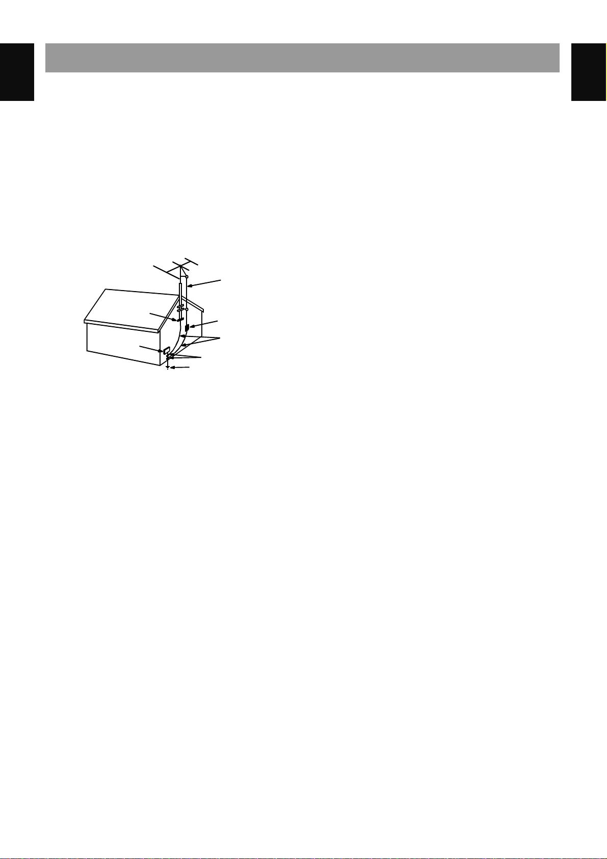
13.Outdoor Antenna Grounding - If an outside antenna is
connected to the receiver be sure the antenna system is
grounded so as to provide some protection against voltage
surges and built-up static charges. Article 810 of the National
Electrical Code, ANSI/NFPA 70, provides information with
regard to proper grounding of the mast and supporting
structure, grounding of the lead-in wire to an antenna-dis
charge unit, size of grounding conductors,location of antennadischarge unit, connection to grounding electrodes and
requirements for the grounding electrode. See Figure 1.
14.Non-use Periods - The power cord of the appliance should be
unplugged from the outlet when left unused for a long period
of time.
15.Object and Liquid Entry - Care should be taken so that objects
do not fall and liquids are not spilled into the enclosure through
openings.
16.Damage Requiring Service - The appliance should be
serviced by qualified service personnel when:
a) The power-supply cord or the plug has been damaged; or
b) Objects have fallen, or liquid has been spilled into the
appliance; or
c) The appliance has been exposed to rain; or
d) The appliance does not appear to operate normally or
exhibits a marked change in performance; or
e) The appliance has been dropped, or the enclosure
damaged.
17.Servicing - The user should not attempt to service the
appliance beyond that described in the operating instructions.
All other servicing should be referred to qualified service
personnel.
ANTENNA DISCHARGE UNIT
(NEC SECTION 810-20)
ANTENNA LEAD
IN WIRE
POWER SERVICE GROUNDING
ELECTRODE SYSTEM
(NEC ART 250 PART H)
GROUND CLAMP
ELECTRIC
SERVICE
EQUIPMENT
GROUNDING CONDUCTORS
(NEC SECTION 810-21)
GROUND CLAMPS
EXAMPLE OF ANTENNA
GROUNDING
NEC - NATIONAL ELECTRICAL CODE
Specifications
1
2
3
4
5
6
7
8
9
10
11
12
13
14
15
1
2
3
4
5
6
7
8
9
10
11
12
13
14
15
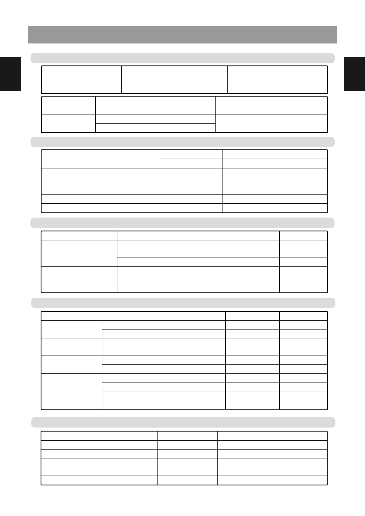
Input Sen./Impedance
Output Level/Impedance
Frequency Response
Crosstalk
S/N Ratio
Composite Video (Video)
Composite 75 ohm
S-Video (Y/C) 75 ohm (DVD only)
Component Out(Y/ Cb/ Cr) : Option
Ref 500 KHz
@1 MHz
DVD
1 Vp-p / 75 ohm
1 Vp-p / 75 ohm
1 Vp-p / 0.286 Vp-p
1V p-p / 0.7 Vp-p / 0.7 Vp-p
45 dB
60 dB
±
0.5 dB
±
0.5 dB
±
0.5 dB
±
0.5 dB
5 Hz ~ 5.7 MHz
40 dB
Video Section
Tape Section
Tuning Range
Scanning Frequency
Interval
Usable Sensitivity,
75 ohms
S/N Ratio
@1mV IHF-A FILTER
USA Version
Australia/Europe Version
USA Version
Australia/Europe Version
S/N = FM 30dB/MW 20dB, USA Version
S/N = FM 26dB/MW 20dB, Australia/Europe Version
FM Mono USA Version
FM Mono Australia/Europe Version
USA Version
Australia / Europe Version
FM
87.5 ~ 108.0 MHz
87.5 ~ 108.0 MHz
100 KHz
50 KHz
2 uV (17.2dBf)
3 uV (20.8dBf)
60 dB
60 dB
Stereo 65 dB
Stereo 63 dB
Tuner Section
MW(AM)
530 ~ 1,710 KHz
522 ~ 1,620 KHz
10 KHz
9 KHz
75 dBuV
75 dBuV
-
45 dB
45 dB
Item
Tape Speed
Frequency Response
S/N Ratio (with Filter)
Channel Separation
THD (Total Harmonic Distortion)
Wow & Flutter (JIS/WTD)
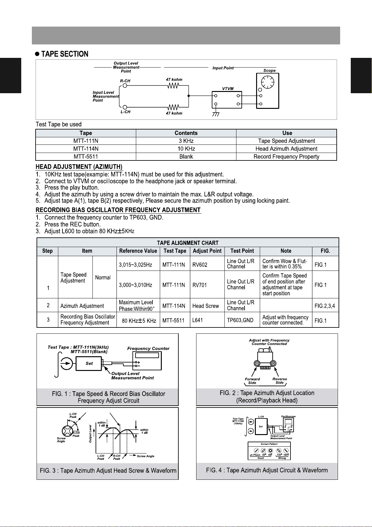
TCC-112, Normal
1KHz = 0dB
TCC-140 / AUX
MTT-141
Playback, TCC-142
TCC-112
3000
±
3%
150 Hz ~ 8KHz
Playback 50dB / Recording 45dB
40dB
1.5 %
0.2
±
0.35%
Model XD-615/ 616/ 625/ 626 XD-618/ 628
Operating Voltage
Power Consumption
AC 100V ~ 240V (50/ 60Hz) AC 230V (50Hz)
Operating 45 Watt Operating 100 Watt
General Specifications
Model XD-615/ 616/ 625/ 626 XD-618/ 628
Set
Speaker
275 x 363.3 x 317.5 / 6.15Kg 275 x 363.3 x 317.5 / 6.2Kg
AS-61VDS : 199 x 251 x 327 / 3.6Kg x 2EA
AS-62NYS : 230 x 458 x 390 / 6.1Kg x 2EA
AS-61WDS : 199 x 280 x 327 / 4.6Kg x 2 EA
POWER OUTPUT at 10 % THD (RMS)
THD (Total Harmonic Distortion)
Input Sen. / Impedance @ 1KHz, 47 K ohms
Output Level / Impedance @ 1KHz
Frequency Response (Analogue)
S/N Ratio IHF-A Weighted
At 1KHz, 6 ohms
At 1KHz, 8 ohms
At 1KHz, 10 W
VIDEO
Tape Rec
at 1W : VIDEO -3 dB
VIDEO
XD-615/625 : 50W / XD-616/626 : 65W
XD-618/628 : 150W
0.10 %
400 mV
±
30 mV / 47K
400 mV
±
30 mV / 2.2K
20 Hz ~ 20 KHz
60 dB
Audio Section
Adjustments
1
2
3
4
5
6
7
8
9
10
11
12
13
14
15
1
2
3
4
5
6
7
8
9
10
11
12
13
14
15
Location of Users Controls
1
2
3
4
5
6
7
8
9
10
11
12
13
14
15
1
2
3
4
5
6
7
8
9
10
11
12
13
14
15
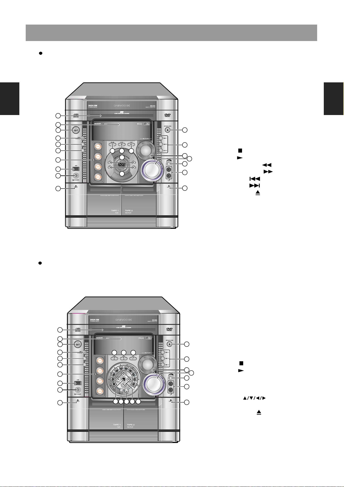
Front Panel : XD-615/616/618[R]
Front Panel : XD-625/626/628[R]
1. Disc tray
2. Display
3. STANDBY/ON button with lamp
4. DISC CHANGE button
5. DEMO button
6. Tape RECORD button
7. FUNCTION : DVD, TUNER(FM/AM),
TAPE1/2 and AUX/DIGITAL button
8. USB jack
9. PHONES jack
10. PAUSE (
II
) button
11. STOP ( ) button
12. PLAY ( ) button
13. ENTER button
14. TEMPO button
15. KEY button
16. Direction( ) buttons
17. Number(0~9) buttons
18. OPEN/CLOSE
()
buttons
19. DISC 1/2/3 buttons
20. MULTI JOG dial
21. MASTER VOLUME Control
22. Mic. VOLUME Control
23. Microphone 1/2 jacks
24. TAPE 1 EJECT button
25. TAPE 2 EJECT button
3
2
1
4
5
6
21
22
25
10 11 12
20
18
8
9
24
16 17
19
23
7
14 15
13
1. Disc tray
2. Display
3. STANDBY/ON button with lamp
4. DISC CHANGE button
5. DEMO button
6. Tape RECORD button
7. FUNCTION : DVD, TUNER(FM/AM),
TAPE1/2 and AUX/DIGITAL button
8. USB jack
9. PHONES jack
10. PAUSE (
II
) button
11. STOP ( ) button
12. PLAY ( ) button
13. FAST REVERSE ( ) /
FAST FORWARD ( ) buttons
14. SKIP PREV ( ) /
SKIP NEXT ( ) buttons
15. OPEN/CLOSE
()
buttons
16. DISC 1/2/3 buttons
17. MULTI JOG dial
18. MASTER VOLUME Control
19. Mic. VOLUME Control
20. Microphone 1/2 jacks
21. TAPE 1 EJECT button
22. TAPE 2 EJECT button
3
2
1
4
5
6
18
19
22
10 11 12
17
15
8
9
21
14
13
16
20
7
Location of Users Controls
1
2
3
4
5
6
7
8
9
10
11
12
13
14
15
1
2
3
4
5
6
7
8
9
10
11
12
13
14
15
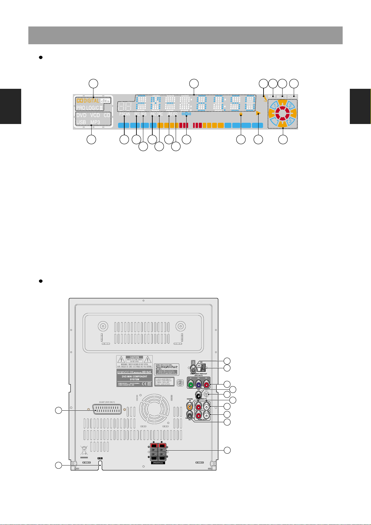
Rear Panel
Display
1 2 43 5 6
87 9 11
10 12
13 15
14
1716 18
1. Sound Mode indicator
2. Multi-Function Information Displaying Area
3. MIC indicator
4. REPEAT indicator
5. ALL/1 indicator
6. DISC indicator
7. Media indicator
8. PROGRESSIVE SCAN Mode indicator
9. Tape RECORD indicator
10. RDS indicator
11. PBC(Playback Control) indicator
12. DRC indicator
13. UBS indicator
14. EQ indicator
15. FM STEREO indicator
16. Lock indicator
17. Disc/Tape Play indicator
18. Disc Tray indicator
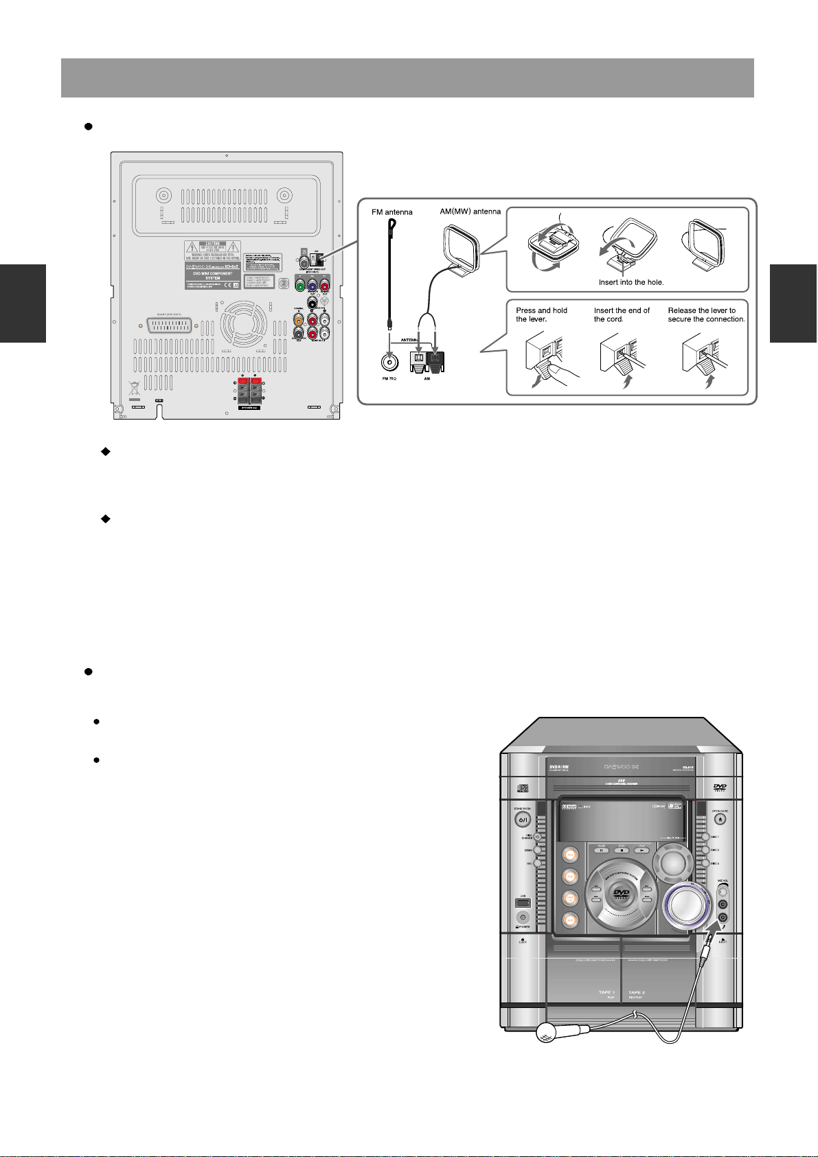
1. FM ANTENNA connector
2. AM(MW) ANTENNA connectors
3. COMPONENT VIDEO OUTPUT
Y/Pb/Pr jacks
4. MONITOR OUT jack
5. S-VIDEO OUT jack
6. COAXIAL INPUT jack
7. AUX INPUT jacks
8. LINE OUTPUT jacks
9. SUB WOOFER OUTPUT jacks
10. SPEAKER connectors
11. SCART jack (Optional)
12. Power cord
1
11
12
2
4
9
6
5
3
7
8
10
Location of Users Controls
1
2
3
4
5
6
7
8
9
10
11
12
13
14
15
1
2
3
4
5
6
7
8
9
10
11
12
13
14
15
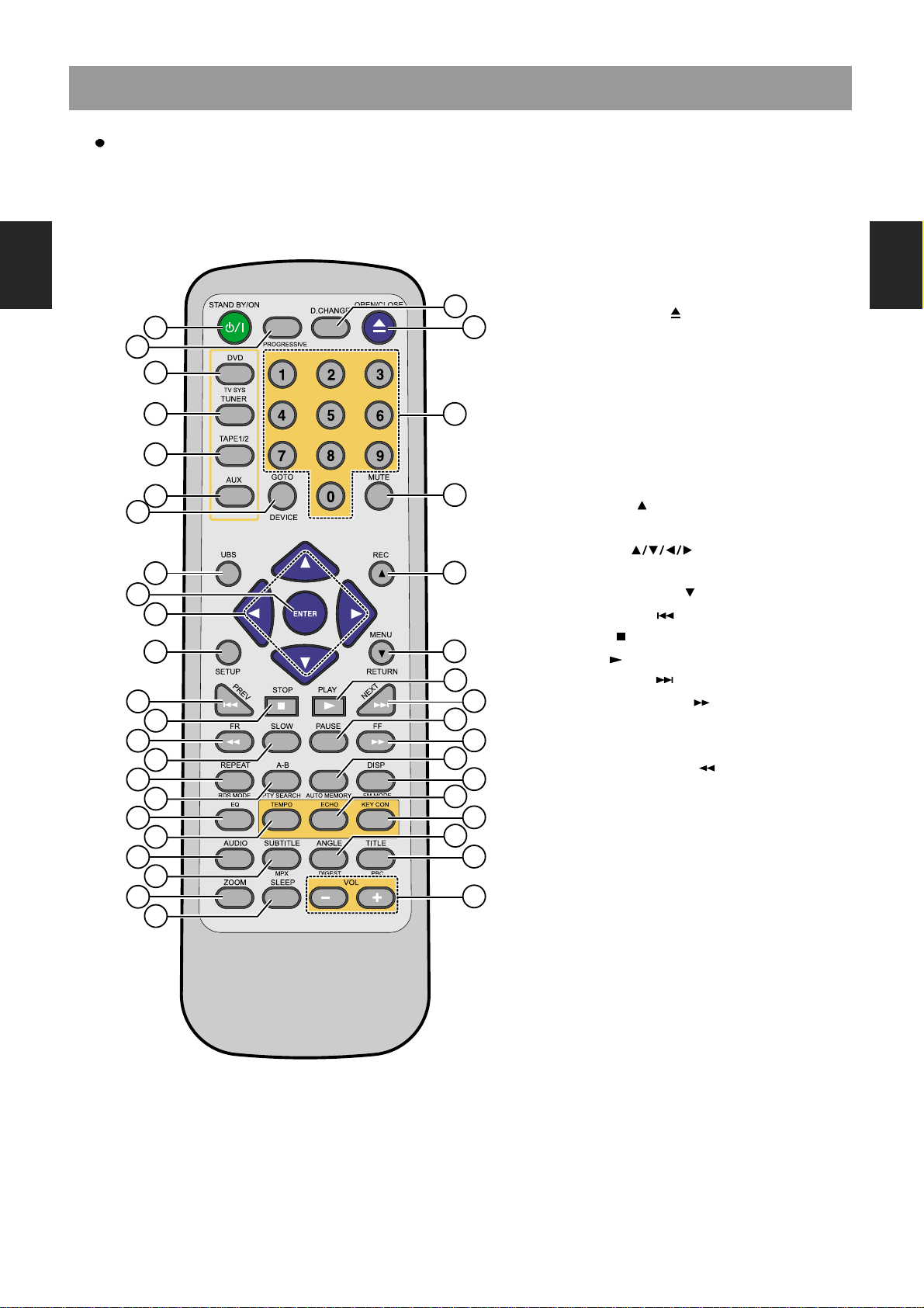
Remote Controller
1. STAND BY/ON button
2. PROGRESSIVE button
3. DISC CHANGE button
4. OPEN/CLOSE( ) button
5. DVD/TV SYS(PAL/NTSC: DVD only) button
6. TUNER button
7. TAPE 1/2 button
8. AUX button
9. Number(0~9) buttons
10. GO TO/DEVICE button
11. MUTE button
12. UBS button
13. RECORD
()
button
14. ENTER button
15. Direction( ) button
16. SETUP button
17. MENU/RETURN
()
button
18. SKIP PREV ( ) button
19. STOP ( ) button
20. PLAY( ) button
21. SKIP NEXT ( ) button
22. FAST REVERSE ( ) button
23. SLOW button
24. PAUSE button
25. FAST FORWARD ( ) button
26. REPEAT/RDS MODE button
27. A-B REPEAT/PTY SEARCH button
28. AUTO MEMORY button
29. DISPLAY/FM MODE button
30. EQ button
31. TEMPO button
32. ECHO button
33. KEY CON button
34. AUDIO button
35. SUBTITLE/MPX button
36. ANGLE/DIGEST button
37. TITLE/PBC button
38. ZOOM button
39. SLEEP button
40. VOLUME -/+ buttons
11
10
14
27
9
13
17
29
28
5
6
7
8
12
15
16
26
23
25
24
22
19
21
20
18
2
4
3
1
31
33
32
30
35
37
36
34
39
40
38
Connecting to Equipment
1
2
3
4
5
6
7
8
9
10
11
12
13
14
15
1
2
3
4
5
6
7
8
9
10
11
12
13
14
15
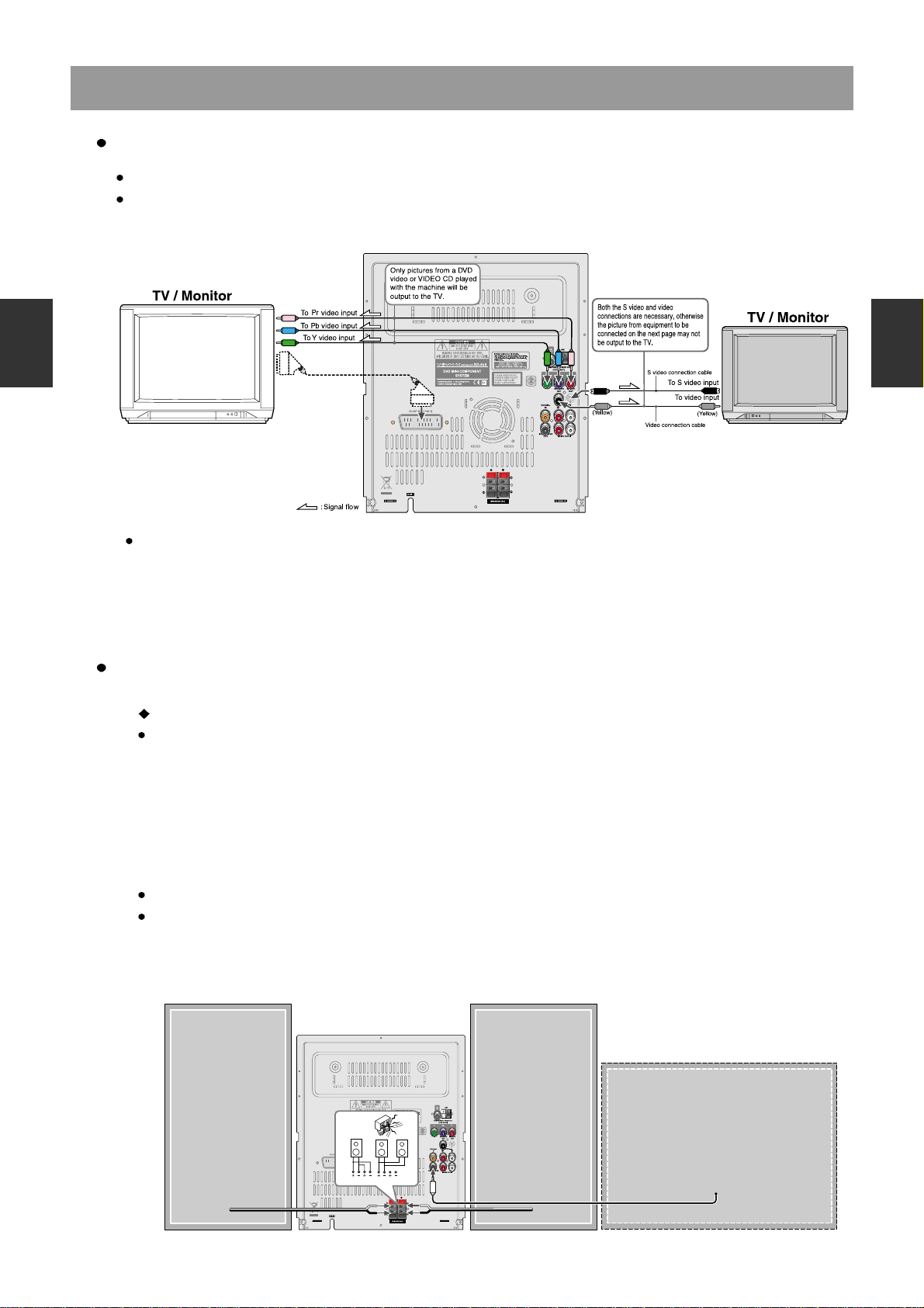
Connecting to TV
Connecting speakers
If the TV or monitor is equipped with an S video input, make the S video connection in addition to the normal video
connection. The S video connection will provide higher quality picture playback.
21-Pin SCART Cable(not included) to 21-pin SCART input terminal on TV
SCART Specification(Europe model only) : Composite and Component Video output(DVD, Video)Audio L/R
Output(DVD only)
for EU version: optional
Before connecting
This machine is designed to reproduce optimum sound quality when speakers with the specified impedance below
are connected. Please check the following information and choose speakers with appropriate impedance for the
connections.
Front speakers(L/R) :
XD-615/616/625/626[R] : 6 ohms min. per speaker
XD-618/628[R] : 8 ohms min. per speaker
To prevent damage to circuits, never short-circuit the positive (+) and negative (-) speaker wires.
Do not connect the speaker cable to the L and R connectors at the same time and do not connect more than one
speaker to the same speaker connectors.
Right speaker Left speaker
Subwoofer speaker
(User Option)
R L
R L
NO!
NO!NO!
Connecting to Equipment
1
2
3
4
5
6
7
8
9
10
11
12
13
14
15
1
2
3
4
5
6
7
8
9
10
11
12
13
14
15
Connecting the supplied FM/MW(AM) antennas
Connecting the microphone for KARAOKE
Adjusting the position of the FM antenna
While listening to an FM program, extend the antenna and move it in various directions until the clearest signal is
received, then secure the antenna with push pins in the position with the least distortion.
Adjusting the position of the AM(MW) antenna
While listening to a AM(MW) program, set the antenna in the direction and position where you receive the clearest
sound.
Put it as far away as possible from the unit, TVs, speakers, cables, and power cords.
Plugging a dynamic microphone to sing along with CD, VCD, DVD
or AUX(also while recording).
Connect the plugs securely.
Firmware Download Method
1
2
3
4
5
6
7
8
9
10
11
12
13
14
15
1
2
3
4
5
6
7
8
9
10
11
12
13
14
15
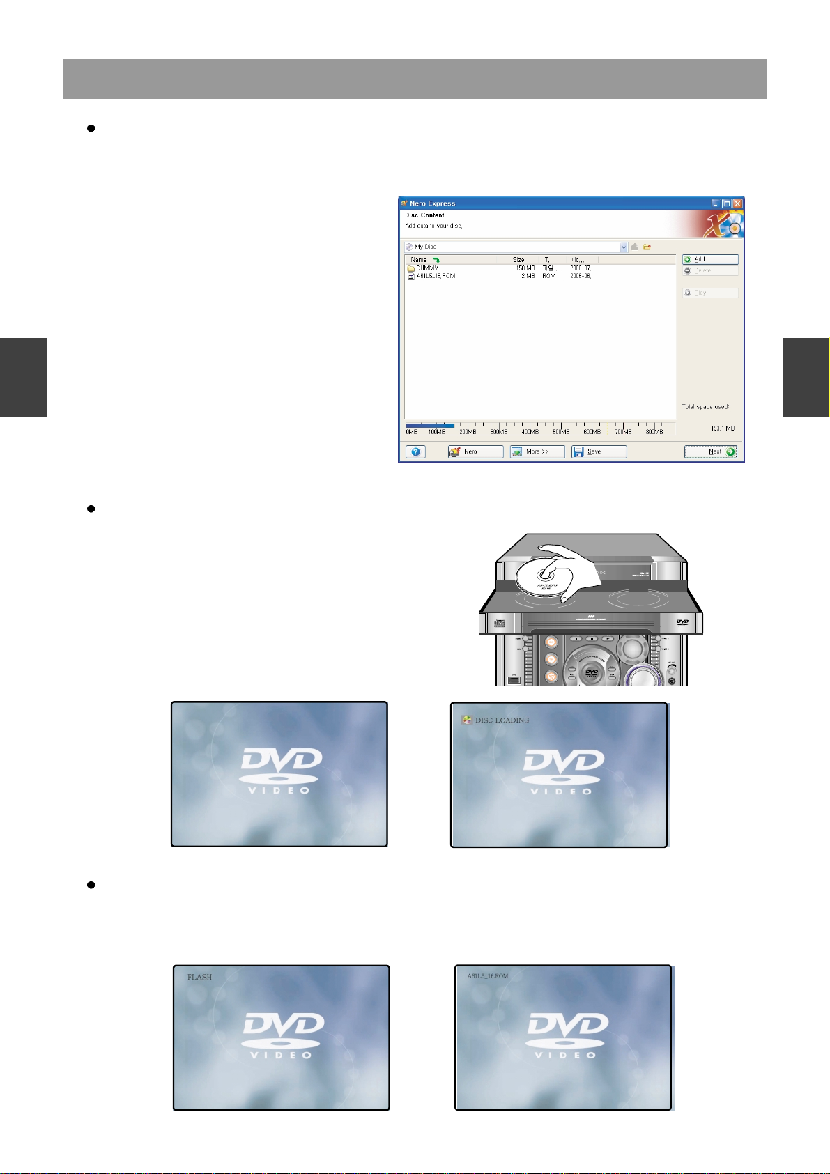
Preparing the Firmware Upgrade
Activating the Firmware Upgrade
1. Write a disc to Update file by PC Writing Program.
2. A size of dummy folder is more than 10M bite. (ex : font_dw, attached picture)
3. Put Firmware file in a disc or USB Card.
<Update by CD-R>
1. Open the Door of DVD Receiver.
2. Insert the Update Disc into the Disc Tray.
3. Close the Door, then DVD Receiver reads the disc,
and Update the Firmware itself.
<Update by USB>
1. Insert the USB Card while the disc is stopped, and
Update the Firmware itself.
• Filename : A61L5_ 16.ROM
Starting Update.
1. Detect the Update Disc.
2. Display for Update Version.
• Basic Version : XD- 615/ 616/618, XD- 625/ 626/628 ( A61L5_ 16. ROM )
Note : Before using the USB devices, make sure
there is no disc on the machine. USB
function works only under the condition
that the display shows “NO DISC” or
“STOP” at DVD function mode.

Firmware Download Method
1
2
3
4
5
6
7
8
9
10
11
12
13
14
15
1
2
3
4
5
6
7
8
9
10
11
12
13
14
15
• While updating, if the door opened or closed by touch, or power button is pressed, the Flash Memory
will be damaged (Same as USB).
• Must be press “Default” or “Reset” on the Setup Menu, Finished Update New Firmware.
Read the Disc or USB Card, Checksum Check and Update New Firmware.
Completed Update.
Caution
1. Automatically open the Door, after Read from Disc. (Disc only)
2. Take a disc out of a Tray. (Disc only)
1. Automatically Video Output off, after Complete Update.
2. Remove the USB Card.
3. Press Power Button twice(off
on)
4. The system is working.
Check the Update Version.
1. Open the Door of UNIT.
2. Press Audio Button or Subtitle Button.
• Audio Button : Check for MPEG Firmware Version.
• Subtitle Button : Check for Loader Firmware Version.

Code Free Method & EEPROM Reset
1
2
3
4
5
6
7
8
9
10
11
12
13
14
15
1
2
3
4
5
6
7
8
9
10
11
12
13
14
15
Preparing the Code Free Method
1. Press “Open” button.
2. Press “Setup” button.
3. Press Number button.
(5
4 2 5)
4. You can see window for Code Free.
5. Press “Enter”, or “Right Arrow”
button.
6. Select Region Number.
7. Press “Left Arrow” button.
8. If you Press “Setup”, The Setting of
Code Free is finished.
XD-610/620 Series EEPROM Reset
Use Only this case : change Flash Memory
1. Door Open.
2. Press Setup Key.
3. Press Number Key(2-5-8-0)
4. Display as follows,
“EEPROM CLEAR TWICE POWER ON/OFF”
Power off Power on Power off Power on.
Check Region Code.
Check Video Mode.
Notice
Trouble Shooting Guide
1
2
3
4
5
6
7
8
9
10
11
12
13
14
15
1
2
3
4
5
6
7
8
9
10
11
12
13
14
15
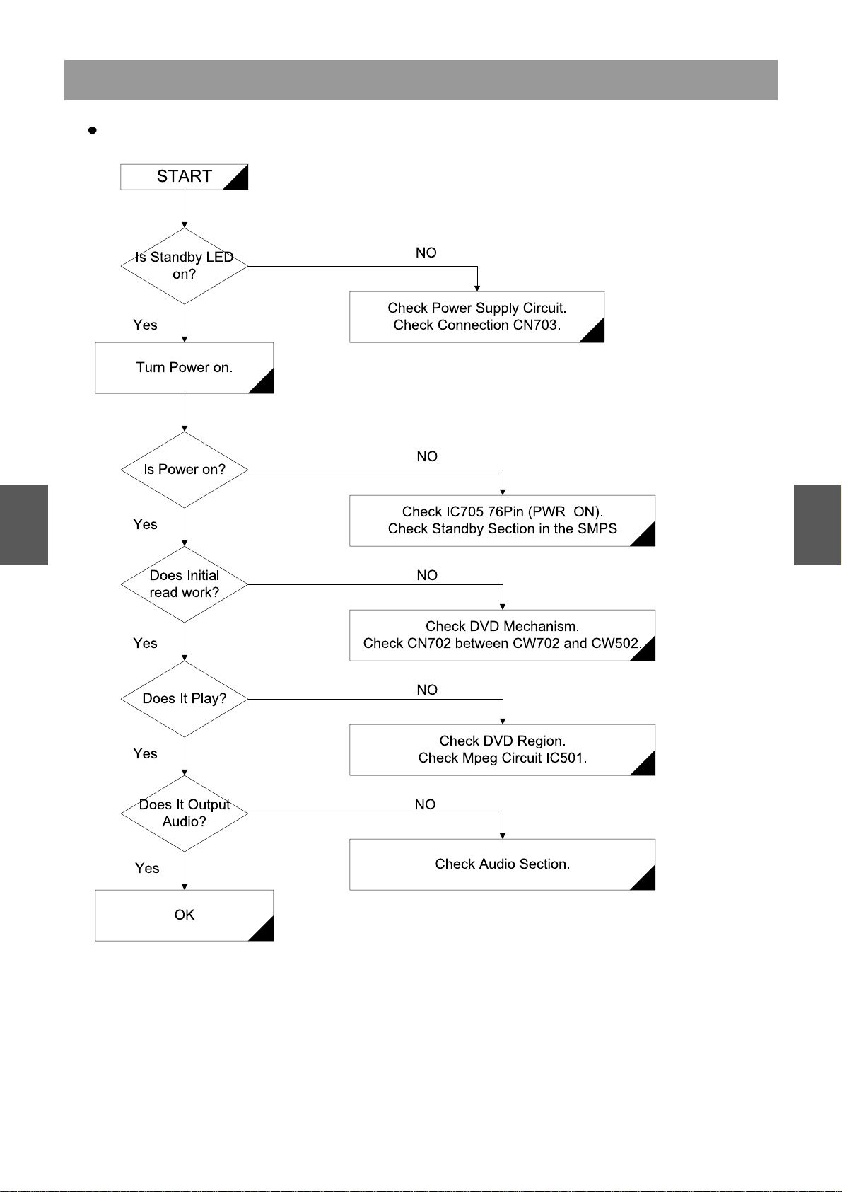
Basic Operating
 Loading...