


DC-B83D1D
Daewoo DC-B83D1D, SH-7800K, SH-7700K, SD-3800K, DC-B84D1S Service Manual
...
S/M No. : VDCB83PET0
Service Manual
MODEL: DC-B83D1D
DC-B84D1S
DC-B84D1D
DC-B85D1D
DC-B86D1D
DC-B86D1P
DC-B87D1D
DC-B88D1D
DC-B89D1D
DC-B8CD1D
HV-DX3E
HV-DX3EV
HV-DX3SP
✔ Caution :
In this Manual, some parts can be changed for improving, their
performance without notice in the parts list. So, if you need the latest
parts information,please refer to PPL(Parts Price List) in Service
Information Center (http://svc.dwe.co.kr).
DAEWOO ELECTRONICS Corp.
MAY. 2004
http : //svc.dwe.co.kr

1
SPECIFICATIONS...............................................................................................................2
ADVANTAGES OF THIS PRODUCT....................................................................................3
TROUBLE SHOOTING....................................................................................................................5
WAVEFORMS................................................................................................................................23
CIRCUIT DIAGRAM.......................................................................................................................26
PCB CIRCUIT BOARD..................................................................................................................36
INSTRUMENT DISASSEMBLY.....................................................................................................39
ELECTRICAL PARTSLIST............................................................................................................45
CONTENTS
2
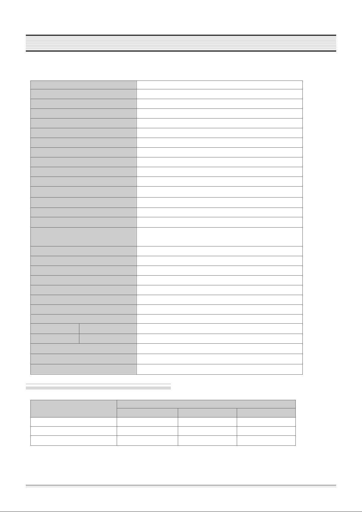
SPECIFICATIONS
Disc type
DVD VIDEO-CD CD
Analogue Audio output 48/96KHz sampling 44.1KHz sampling 44.1KHz sampling
Digital Audio output 48KHz sampling 44.1KHz sampling 44.1KHz sampling
Optical digital audio output 48KHz sampling 44.1KHz sampling 44.1KHz sampling
Output
Power 200-240V~, 50/60Hz
Consumed electricity 22W
Weight 4.6kg
Dimension (W x H x D) 435mmx93mmx255mm
Operative temperature +5°C~40°C
Installation condition Horizontal / Relative humidity under 80%
Laser output 5mW (continuous wave max.)
Wave length 635nm (DVD), 730nm (CD)
Signal type PAL COLOR
Antenna Input/output U/V-mixed: 75Ωunbalanced
VIDEO input 1.0Vp-p (unbalanced, RCA JACK)
AUDIO input -8.8dBm, RCA JACK
VIDEO output
(common use of DVD and VCR)
VIDEO output terminal, 1.0 Vp-p unbalanced, RCA JACK, SCART JACK
VIDEO output (DVD only) RGB output (75ΩIn load R: 0.7Vp-p, G:0.7Vp-p, B:0.7Vp-p)
AUDIO output
(common use of DVD and VCR) Audio output terminal (2 kinds): -5.8dBm(VCR), 2Vrms(DVD), RCA JACK
AUDIO output (DVD only) Analogue AUDIO output : 2.0Vrms
Digital audio output (OPTICAL, COAXIAL)
Playable tape Very high dense tapes with VHS marks
Playable disc DVD, VIDEO-CD, CD (12cm), CD (8cm), MP3, CD-R, CD-RW
Tape speed SP: 23.39mm/s, LP: 11.70mm/s
Playtime SP: 3hrs, LP: 6hrs (use of E180tape)
Clock display 24 hrs
Time Recording 8 programs a month
Persistence in power failure 1min
VIDEO S/N (VCR) Over 43dB(Standard recording)
Resolution VCR Over 240 lines (Standard recording)
DVD Over 400 lines (Playback DVD)
AUDIO (VCR) Over 65dB
AUDIO (DVD) 90dB
AUDIO dynamic range 90dB
DVD Audio output standards

ADVA NTAGES OF THIS PRODUCT
3
• DVD, VCD, CD, CD-R(MP3), CD-RW, VHS
• Watching DVD for recording broadcast
• Integrated remote control (VCR, DVD)
• VISS function
• Multiplex sound playback/record
• High Sound Quality of 6 head Hi-Fi
• Simple record function
• MP3 file playback function (CD-R disc having records of MP3 files)
• GUI (Graphical User Interface) through OSD (On Screen Display)
By using the [DISPLAY] button on the remote control, information on the DVD/VCD/CD player and disc, can be
displayed on the TV screen.
• Screensaver function (DVD)
• 3D sound (3D sound effect using 2 speakers)
• High bit / High sampling with 27MHz / 10bit video encoder
• High bit / High sampling with 96MHz / 24bit Audio D/A Converter
• Coaxial, Optical digital Audio output (PCM, Dolby Digital, dts)
You can enjoy high-level digital audio by connecting with amp embedded with Dolby Digital / dts decoder.
• Built-in Dolby Digital decoder (DVD)
• Analog audio 2-channels output for DOWNMIX (x1)
• Composite video output (x1)
• Slow Forward / Reverse playback (DVD)
• Fast Forward / Reverse playback
• Search of title, chapter, and time in DVD disc, and search of time and track time in VCD.
• Various TV aspect (DVD)
4:3 for Pan and Scan, 4:3 for Letter Box, and 16:9 for Wide
• Repeat playback (title, chapter, and part for DVD/ track, disc, and part for VCD/CD)
• Selective Play (DVD/VCD/CD)
You can select and play the desired title / chapter of DVD and track of Video CD/CD in STOP mode.
• Parental Lock function (DVD)
This function can prevent playback of software that may be unsuitable for children.
• Multi Audio function (DVD)
The audio soundtrack can be heard in up to 8 languages. In the case of SVCD or VCD, it depends on the disc. (The
number of audio languages depends on the software.)

4
ADVANTAGES OF THIS PRODUCT
• Multi Subtitle function (DVD)
The subtitle can be seem in up to 32 languages. In the case of SVCD or VCD, it depends on the disc. (The number of
subtitle languages depends on the software.)
• Multi Angle function (DVD)
This function allows you to choose the viewing angle of scenes which were shot from a number of different angles.
(The number of angles depends on the software.)
• Screen zoom function (DVD/VCD)
5
TROUBLESHOOTING
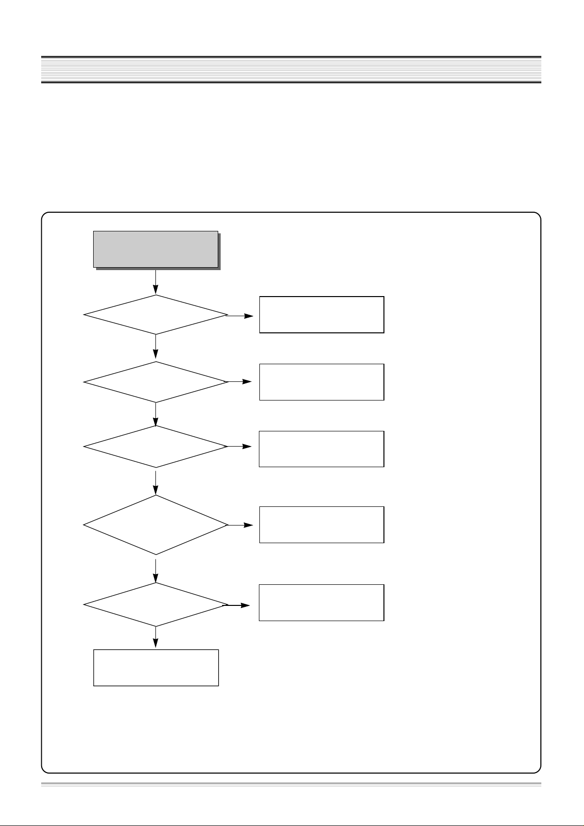
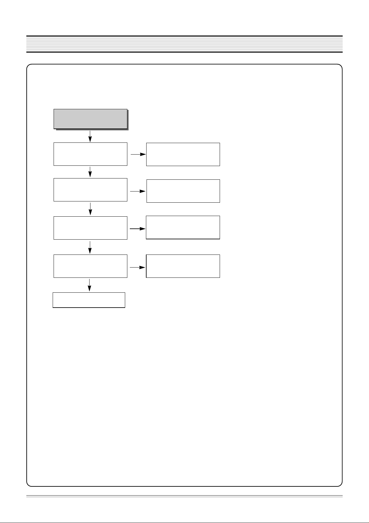
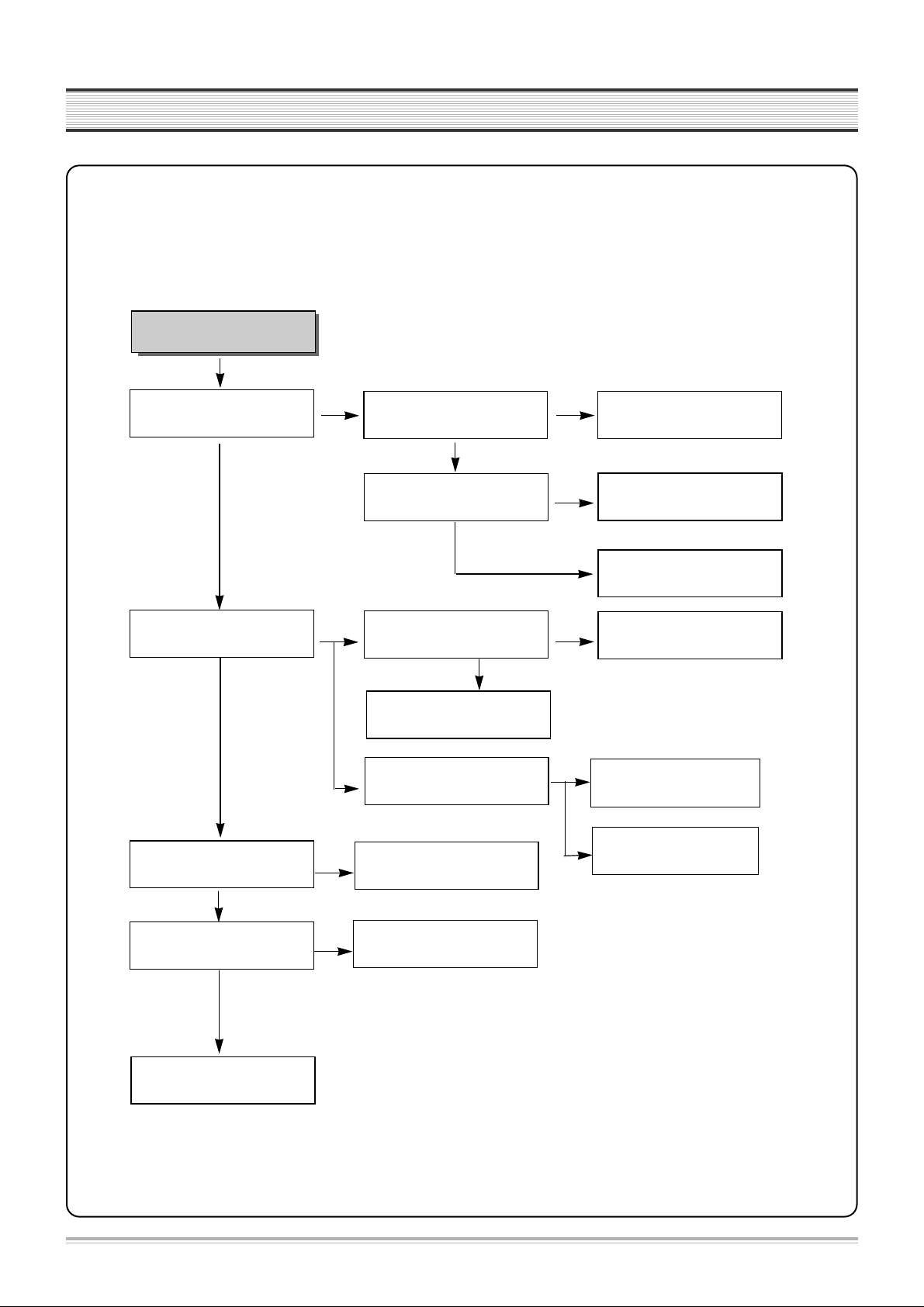
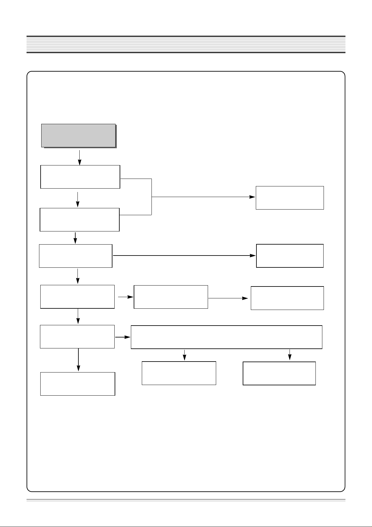
1. POWER CIRCUIT
✓ CAUTION
You must use insulated transformer during the first part test of POWER circuit.
Check IC501, IC701
No power
POWER cord is ok?
Is 400V~200V voltage
obtained at C804 +?
Output voltage of 2
nd
parts is normal?
Check
rectifier diode of 2
nd
parts ;
D821, D822, D823, D824,
D825, D826, D827
Switching
pulse of Q801 collector is
normal?
OK
Exchange POWER CORD
Check F801.
Exchange rectifier diode of 2
nd
parts ; D821, D822, D823, D824,
D825, D826, D827.
Check Q801.
NO
YES
YES
YES
YES
YES
NO
NO
NO
NO
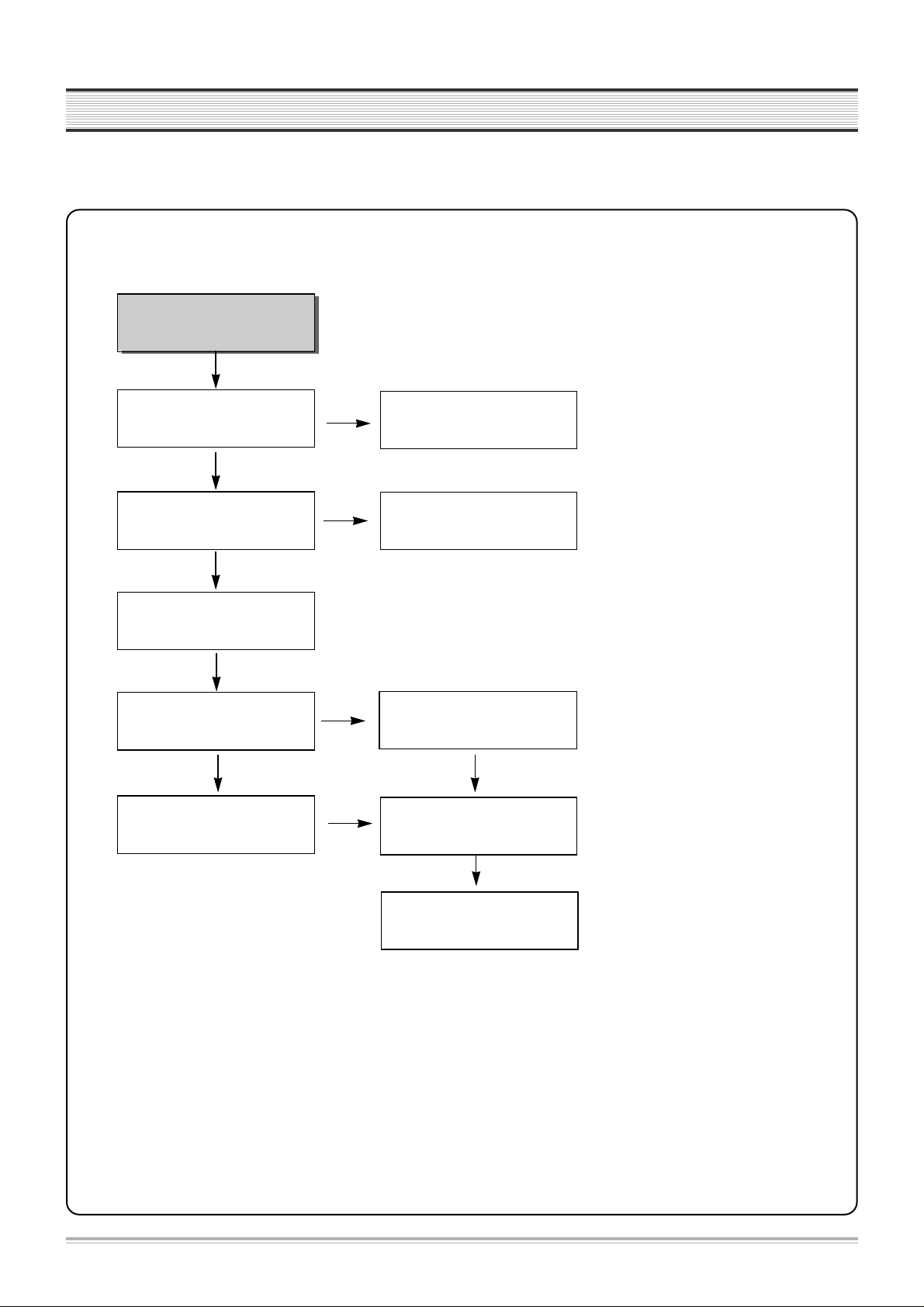
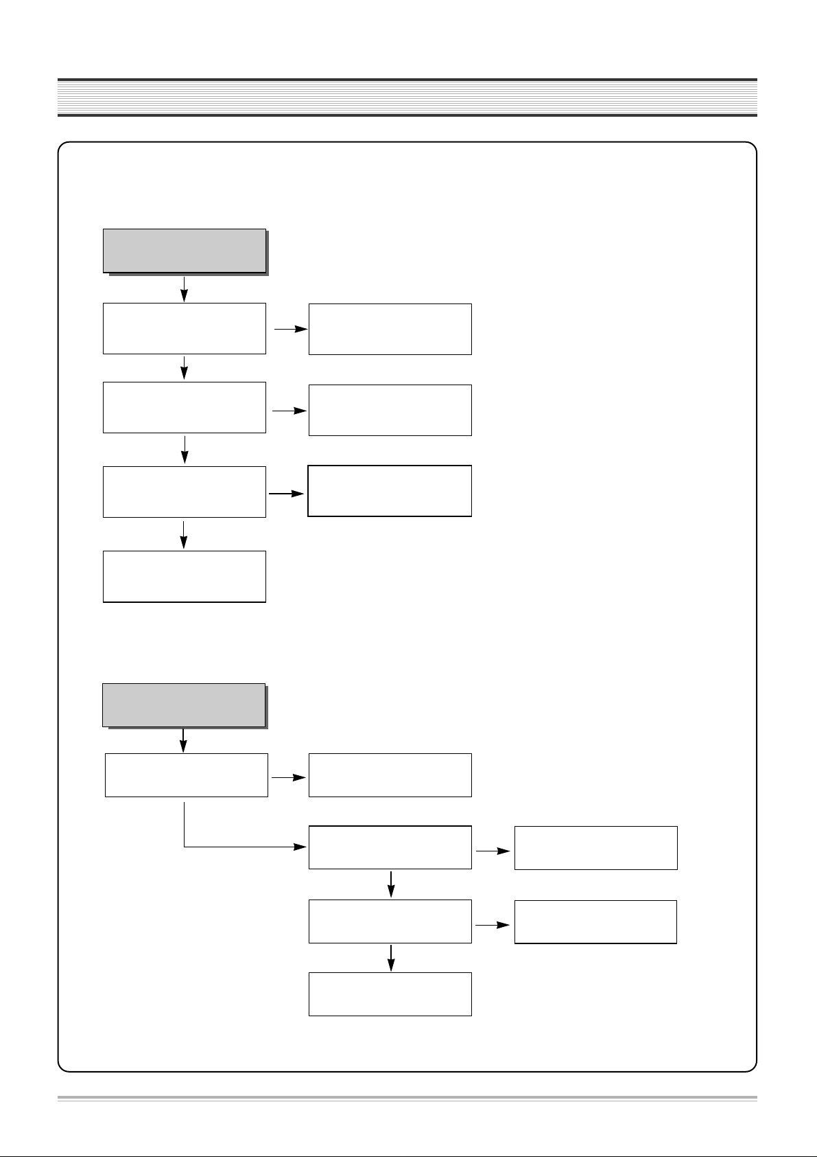
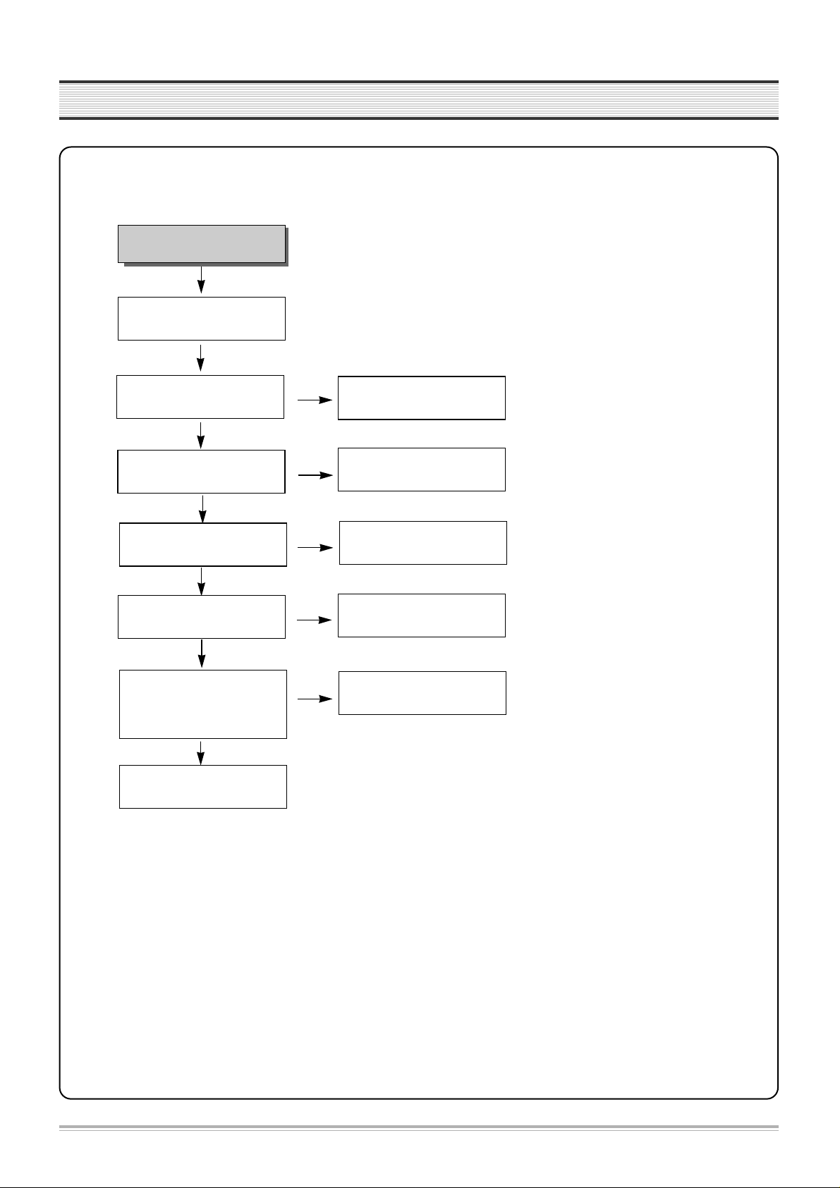
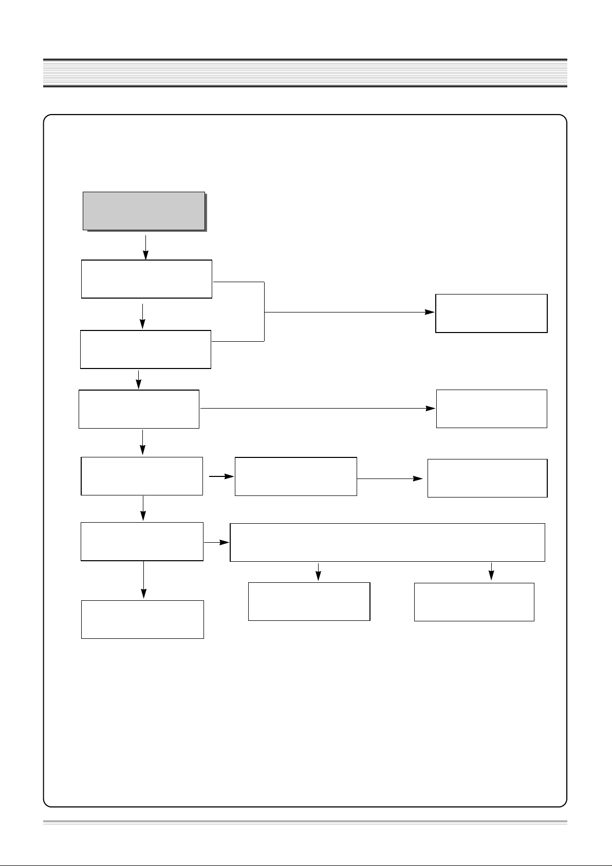
2. SYSTEM CIRCUIT
6
TROUBLESHOOTING
No LED display.
Is 5V obtained at IC701
pin #9, 25?
Oscillation at IC701pin #1?
Specific GRID/SEG doesnt function.
Check R588, D857, L503, L860
Exchange IC701.
Check IC 701 pin #22~24, 27,
28, 30, 31.
Check IC 701 pin #10~12, 14~21.
NO
YES
YES
NO
NO
GRID output at PORT of IC701?
YES
SEGoutput at PORT of IC701?
Exchange IC701.
YES
A. LED DISPLAY
NO
7
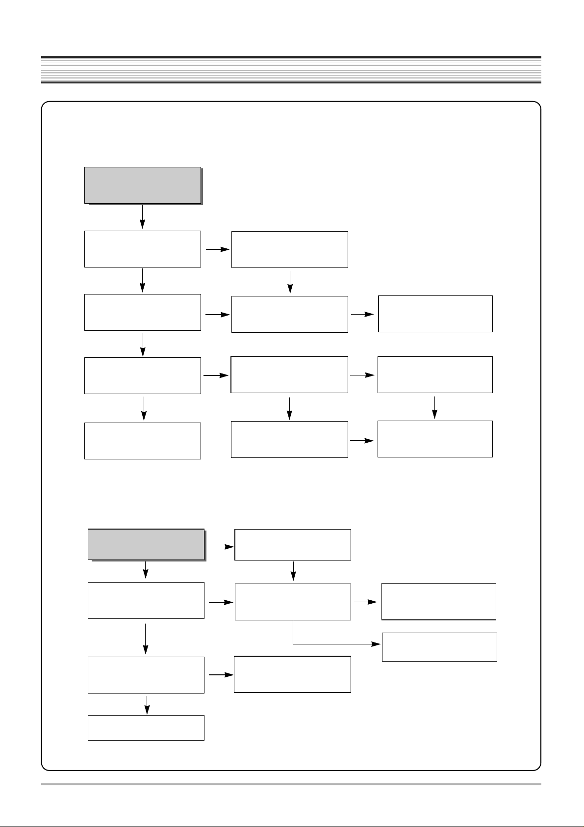
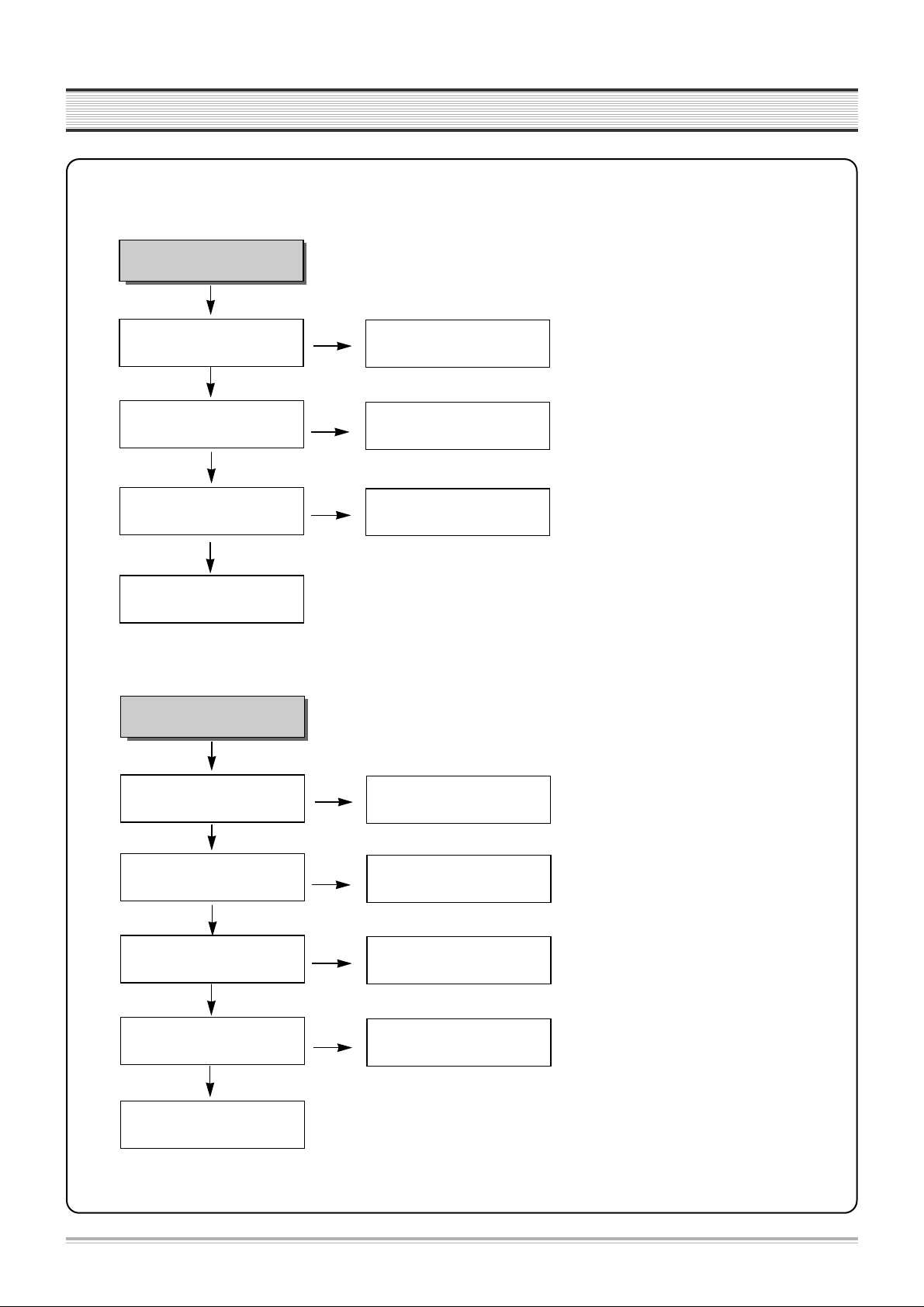
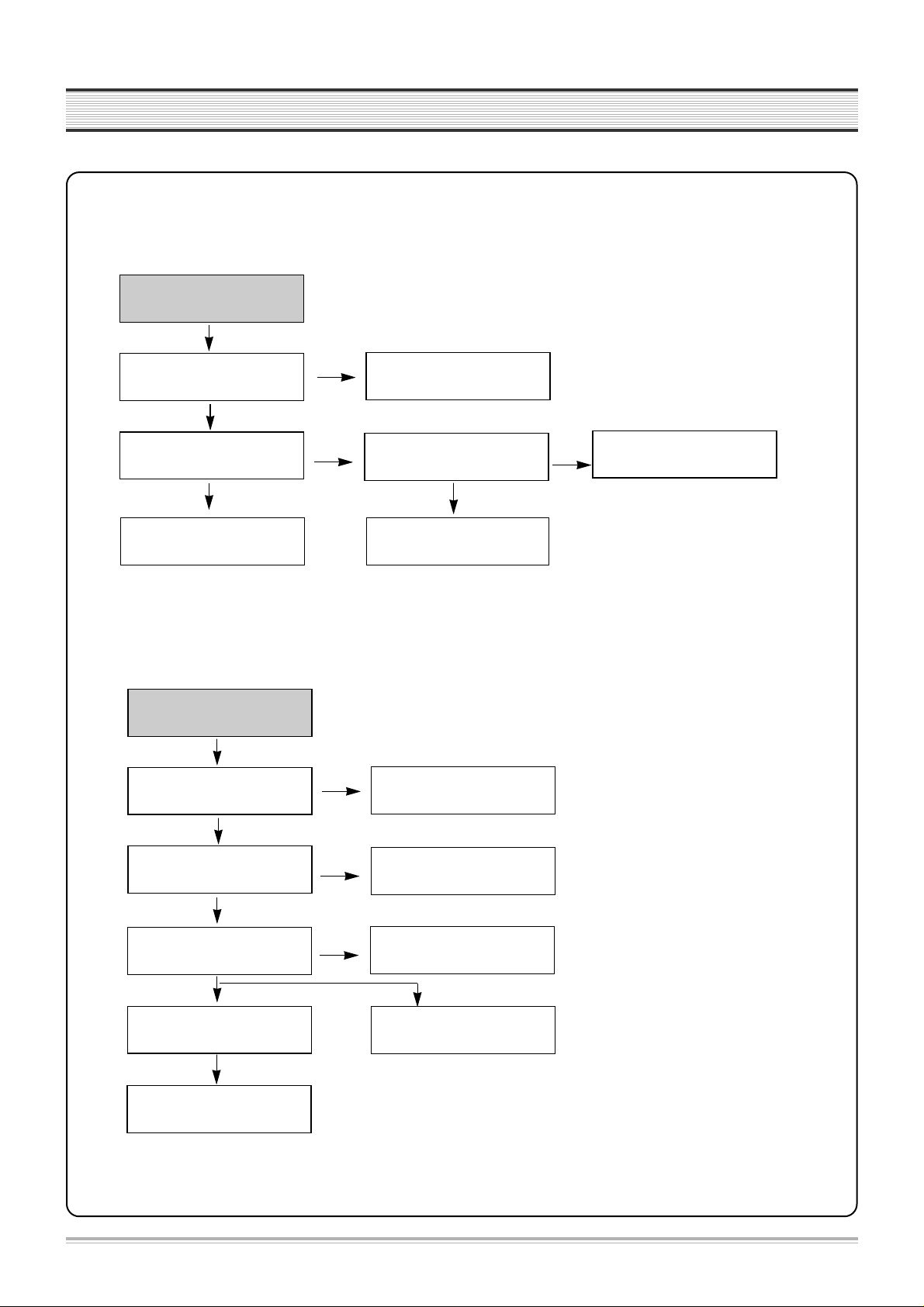
TROUBLESHOOTING
Noise appears on the
playback screen.
Is noise diminished by tracking
adjustment.
Noise band is trembled up and
down?
Re-adjust PATH.
Is the height of CTL HEAD normal?
No dust?
Is there problem in CTL Input
circuit and amplifier.
YES
NO
NO
NO
Is there CTL pulse at IC501
pin#97?
Check IC501.
Noise appears on the screen even
though changing tape.
Re-adjust the height of AC HEAD.
Remove the dust.
Check C510,R545~R547
IC 501 pin #91, 92, 98.
NO
Re-adjust PATH.
B-1. Bad playback quality (1)
YES
YES
YES
YES
Noise appears on the Full
playback screen.
Are SW pulse and HA SW normal?
Recheck step B-1
(Bad playback quallty (1)).
Check HEAD AMP connector
and HEAD.
YES
YES
NO
NO
ENVE Wave at PT01 pin #4?
Check VIDEO circuit.
Are there SW, HA SW pulse at
IC501 pin #16, 18?
Check PCB Pattern.
Check IC501.
B-2. Bad playback quality (2)
YES
NO
YES
8
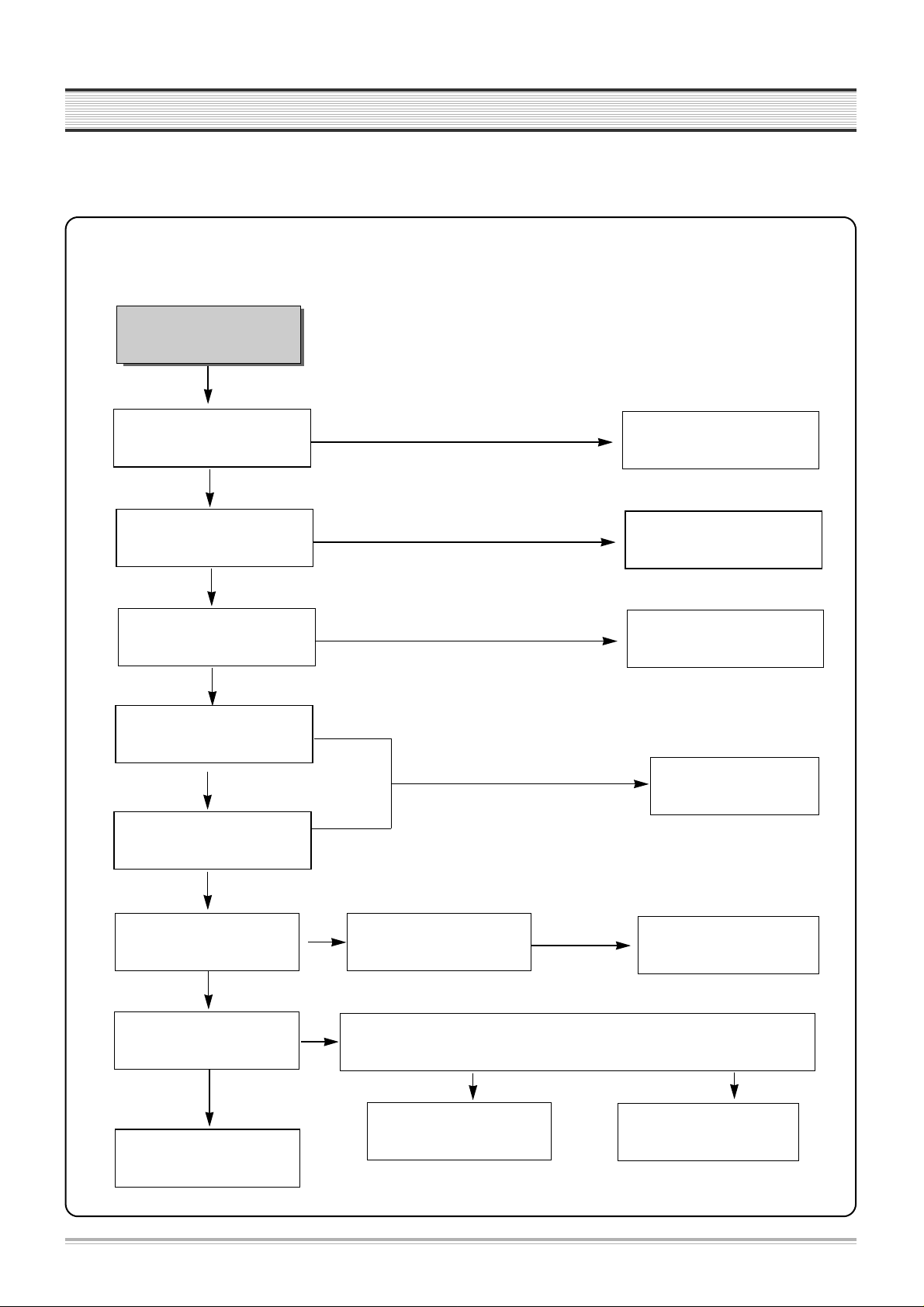
TROUBLESHOOTING
No broadcasting signal
received
Is the output at IC501 pin# 61(CLK),
60 (DATA) normal?
Is SIF,Video output at TMI(RF101)
pin#16,19 normal?
Check IC 501.
Check IC301.
Check IC501.
YES
YES
NO
NO
NO
Is Video Signal input at IC501
pin#50?
Is there Video output at IC501
pin#52?
Check TMI (RF101) Block.
NO
Check Video Buffer Q670, Q671
C. No broadcasting signal received
YES
YES
YES
9
TROUBLESHOOTING
Cassette tape isn t inserted.
Is 5V voltage obtained at Loading
parts IC501 pin#2?
Is 14V voltage obtained at
Capstan Motor P501 pin#2?
Check at EVER 14V
Check Q850.
Connect Capstan and Loading Motor.
Check connector and Capstan Motor.
YES
NO
NO
NO
Is 13V voltage obtained at Each
parts of Loading Motor?
Replace Loading Motor.
Check D851 and POWER circuit.
D. No CASSETTE Loading
YES
YES
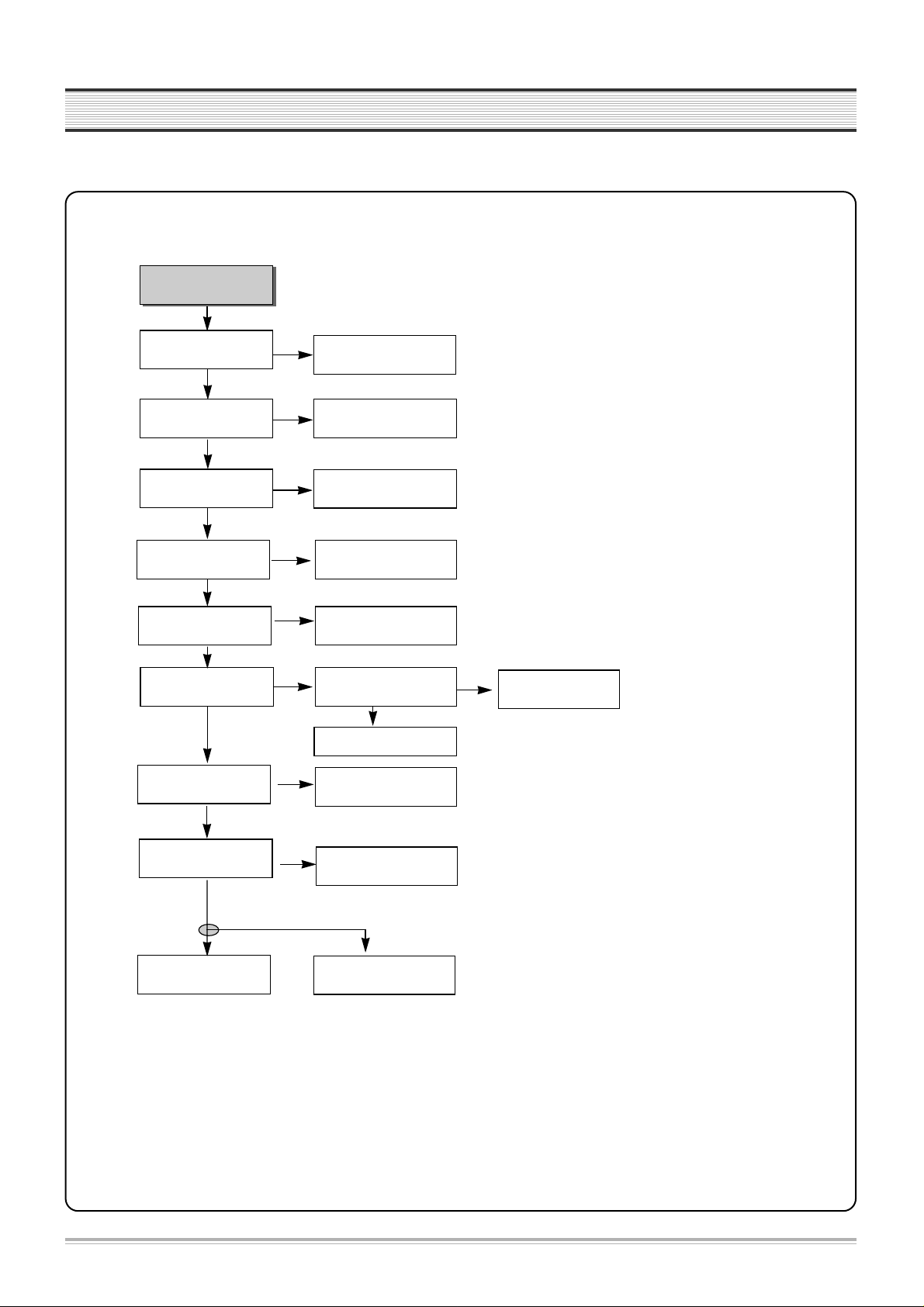
E. AUTO STOP in Playback mode
VCR stops automatically in
playback mode.
Check R544,C516 and P501
pin#11.
Check S501, S502 REEL Sensor.
Is D.PG/FG pulse at IC501
pin#90 normal ?
Is C. FG pulse at IC501 pin#87
normal ?
Is there REEL Pulse at IC501
pin#79, 80?
Check and replace IC501.
NO
YES
YES
YES
NO
Check C.FG(R543,C517) and
P501 pin#1.
NO
10
TROUBLESHOOTING
F. DRUM Motor stops
G. CAPSTAN doesn t rotate
CAPSTAN doesn t rotate.
Is EVER 14V voltage obtained
at P501 pin#2?
YES
NO
NO
NO
YES
YES
Is Capstan PWM fit to
IC501 pin#77?
Is 3.2V voltage obtained
at P501 pin#5?
Is 2.7V voltage obtained
at P501 pin#9?
Check P501 Connector and
Capstan Motor.
Check EVER 14V.
(Q850)
Check Capstan FG
(IC 501 pin# 87).
Check
R541,R540,R539,R538,C518
Check R537,R536,C521
DRUM Motor stops.
Is 14V voltage obtained at P501
pin#8?
YES
NO
NO
NO
YES
YES
Is DRUM PWM fit to IC 501
pin#76?
Is 2.6V voltage obtained at
P501 pin#12?
Check Capstan Motor and
DRUM Motor.
Check EVER 14V
(Q850).
Check DRUM PG/FG
(IC 501 pin# 90).
Check R534,R535,C519,C520.
NO
11
TROUBLESHOOTING
3. VIDEO circuit
A. EE screen doesn t appear
EE MODE Picture NG
Is Video signal input at
IC301 pin#48,50,52,54?
Is 5V supplied at
pin#42,55,72,91of IC301?
Is C.S, DATA, CLOCK signal
input pin#67,68,69 of IC301?
Check IF and LINE IN JACK.
Check POWER circuit.
Check IC501
pin #58,71,72.
NO
YES
YES
NO
NO
YES
Is signal output from pin#65 of
IC301?
YES
NO
Check IC301
pin#62 Q-V Sync.
Is signal input into pin#50
of IC501?
YES
NO
Check PCB Pattern.
Is signal output from
pin#52 of IC501?
YES
NO
Is 5V supplied to pin#53, 98,
99 of IC501?
Is signal output at IC301
pin#61?
YES
NO
Check PCB Pattern
Q309, Q310.
Check IC 501
YES
Check POWER circuit.
NO
Is signal input at IC301
pin#56?
Check RF Output.
Check PCB Pattern & LINE
out.
YES
YES
Check IC301.
NO
12
TROUBLESHOOTING
B. Playback picture doesn t appear
YES
YES
Is Y SIGNAL output at IC301
pin#46?
Is VIDEO SIGNAL output at IC301
pin#65?
Check and Replace IC301.
PB video signal missing.
Is Envelope output from IC301
pin#79?
NO
NO
Same as EE MODE check.
Is 5V supplied at IC301 pin#91?
Is SW Pulse input at IC301
pin#70?
Is 5V obtained at IC301 pin#24,
42,55,72,91?
Check POWER 5V.
Check IC501 pin#18.
Clean head or Replace head.
Check POWER 5V.
NO
NO
Check PATTERN
NO
YES
YES
YES
YES
YES
YES
NO
Does X301(4.43MHz)
oscillate?
Is Y SIGNAL input at IC301
pin#43?
NO
Check PATTERN
YES
NO
Replace X301.
NO
Check and replace IC301.
13
TROUBLESHOOTING
Is +5V supplied at IC301 pin#91?
NO
NO
YES
YES
Is VIDEO SW Pulse input at IC301
pin#70?
Is REC signal output from IC301
pin#94,95,89,90?
LP MODE: 89,90 Pin
SP MODE: 94,95Pin
Check video HEAD and Connector.
Is signal input into IC301
pin# 48,50,52,54,56?
Check POWER circuit.
Check IC501 pin#18.
Record video signal poor.
Check EE MODE.
YES
Is luminance and color signal
output from IC301 pin#78?
Replace IC301.
NO
NO
YES
C. No recording
YES
Is IC301 pin#80 REC(H) HIGH?
Check IC501 pin#45.
NO
14
TROUBLESHOOTING
NO
Is Video signal input at IC501
pin#50?
Check POWER circuit.
No OSD appears.
Is 5V obtained at IC501 pin# 53,
98, 99?
Is Video signal output at IC501
pin#52?
NO
Replace IC501.
D. No OSD(On Screen Display) appears
YES
YES
NO
Check IC 501.
Check IC 501.
NO
Check PCB Pattern
Check FFC CABLE & DVD
Module
DVD Composite signal doesn t
appear
Is signal output at PD01
pin# 5?
Is signal at IC301 pin#56?
NO
E. No DVD Video
YES
YES
Remark previous 3-A
Is signal at IC301 pin#61?
Check IC301
NO
Check RF output.
YES
YES
Check Line output
15
TROUBLESHOOTING
4. AUDIO (Hi-Fi MODEL)
No sound in RF E-E mode
Is Audio signal output at IC601 pin
#3, 13?
A. No sound in E-E mode
a. RF E-E
Check IC501.
Is Audio signal output at IC251
pin#16,17?
Are CLK and DATA obtained at
IC251 pin#42,43?
NO
Is 5V obtained at IC251 pin#40?
Replace IC251.
YES
YES
Is 12V obtained at IC251 pin#34?
NO
YES
Check POWER circuit.
YES
Replace IC601.
Is 5V obtained at IC051 pin#1?
Check Power circuit.
NO
Is there SIF signal at IC051 pin#2
in RF mode?
Check RF101.
NO
YES
Is there SIF signal out at IC051
pin#30, 31?
Check IC051.
NO
YES
YES
Comparing with switching table, are SWA, B CTL SIGNAL
right at IC601 pin #9,10?
NO
Check Output JACK.
YES
YES
NO
16
TROUBLESHOOTING
b. AV1 E-E
No sound in AV1 E-E mode.
NO
Check Input AV1 JACK
Is Audio signal at IC251 pin#6, 7?
Is Audio signal output at IC601 pin
#3, 13?
Check IC501.
Is Audio signal output at IC251
pin#16,17?
Are CLK and DATA obtained at
IC251 pin#42,43?
NO
Is 5V obtained at IC251 pin#40?
Replace IC251.
YES
YES
Is 12V obtained at IC251 pin#34?
NO
YES
Check POWER circuit.
YES
Replace IC601.
YES
Comparing with switching table, are SWA, B CTL SIGNAL
right at IC601 pin #9,10?
NO
Check Output JACK.
YES
YES
NO
17
TROUBLESHOOTING
c. AV2 E-E
No sound in AV2 E-E mode.
NO
Check Input AV2 JACK
Is Audio signal at IC251 pin#8, 9?
Is Audio signal output at IC601 pin
#3, 13?
Check IC501.
Is Audio signal output at IC251
pin#19, 20?
Are CLK and DATA obtained at
IC251 pin#42,43?
NO
Is 5V obtained at IC251 pin#40?
Replace IC251.
YES
YES
Is 12V obtained at IC251 pin#34?
NO
YES
Check POWER circuit.
YES
Replace IC601.
YES
Comparing with switching table, are SWA, B CTL SIGNAL
right at IC601 pin #9,10?
NO
Check Output JACK.
YES
YES
NO
 Loading...