


KOG-391H0S

Service Manual
Microwave Oven
Model :KOG-371G0S KOG-391G0S
KOG-371H0S KOG-391H0S
KOG-376T1S KOG-396T1S
KOG-371R0S KOG-391R0S
KOG-374R0S KOG-375R0S
KOG-373R0S KOG-393R0S
DAEWOO ELECTRONICS CO., LTD.
✔
Caution
: In this Manual, some parts can be changed for improving, their
performance without notice in the parts list. So, if you need the
latest parts information,please refer to PPL(Parts Price List) in
Service Information Center (http://svc.dwe.co.kr).

11
PRECAUTIONS TO BE OBSERVED BEFORE AND
DURING SERVICING TO AVOID POSSIBLE EXPOSURE
TO EXCESSIVE MICROWAVE ENERGY
(a) Do not operate or allow the oven to be operated with the door open.
(b) Make the following safety checks on all ovens to be serviced before activating the magnetron or
other microwave source, and make repairs as necessary: (1) Interlock operation, (2) Proper door
closing, (3) Seal and sealing surfaces (arcing, wear, and other damage), (4) Damage to or
loosening of hinges and latches, (5) Evidence of dropping or abuse.
(c) Before turning on power to the microwave oven for any service test or inspection within the
microwave generating compartments, check the magnetron, wave huide or transmission line, and
cavity for proper alignment, integrity, and connections.
(d) Any defective or misadjusted components in the interlock, monitor, door seal, and microwave
generation and transmission systems shall be repaired, replaced, or adjusted by procedures
described in this manual before the oven is released to the owner.
(e) A microwave leakage check to verify compliance with the Federal Performance Standard should
be performed on each oven prior to release to the owner .
TABLE OF CONTENTS
SAFETY AND PRECAUTIONS..................................................................................................................................2
1. FOR SAFE OPERATION .....................................................................................................................2
2. FOR SAFE SERVICE PROCEDURES ................................................................................................2
SPECIFICATIONS......................................................................................................................................................3
EXTERNAL VIEW......................................................................................................................................................4
1. OUTER DIMENSION............................................................................................................................4
2. FEATURE DIAGRAM...........................................................................................................................6
3. CONTROL PANEL.............................................................................................................................12
INSTALLATION .......................................................................................................................................................19
OPERATIONS AND FUNCTIONS...........................................................................................................................20
DISASSEMBLY AND ASSEMBLY..........................................................................................................................21
INTERLOCK MECHANISM AND ADJUSTMENT...................................................................................................43
TROUBLE SHOOTING GUIDE................................................................................................................................45
MEASUREMENT AND TEST...................................................................................................................................49
1. MEASUREMENT OF THE MICROWAVE POWER OUTPUT ...........................................................49
2. MICROWAVE RADIATION TEST......................................................................................................50
3. COMPONENT TEST PROCEDURE..................................................................................................51
WIRING DIAGRAM..................................................................................................................................................52
PRINTED CIRCUIT BOARD............................................................................................................54, 60, 66, 72, 77
1. CIRCUIT CHECK PROCEDURE ...............................................................................55, 61, 67, 73, 78
2. PCB CIRCUIT DIAGRAM...........................................................................................57, 63, 69, 75, 80
3. P.C.B. LOCATION NO. ..............................................................................................58, 64, 70, 76, 81
EXPLODED VIEW AND PARTS LIST.....................................................................................................................83
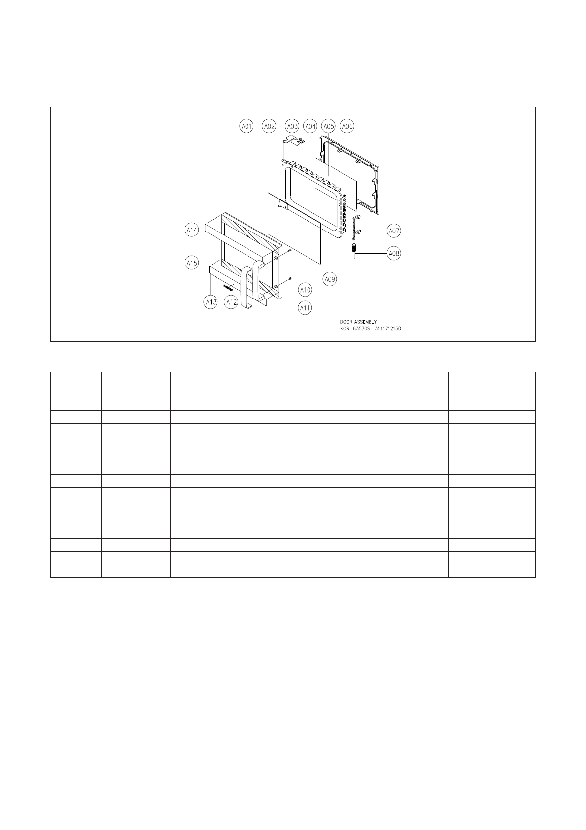
1. DOOR ASSEMBLY ............................................................................................................................83
2. CONTROL PANEL ASSEMBLY.........................................................................................................83
3. TOTAL ASSEMBLY............................................................................................................................83

2
SAFETY AND PRECAUTIONS
1. FOR SAFE OPERATION
Damage that allows the microwave energy (that cooks or heats the food) to escape will result in poor cooking and
may cause serious bodily injury to the operator.
IF ANY OF THE FOLLOWING CONDITIONS EXIST, OPERATOR MUST NOT USE THE APPLIANCE.
(Only a trained service personnel should make repairs.)
1) A broken door hinge.
2) A broken door viewing screen.
3) A broken front panel, oven cavity.
4) A loosened door lock.
5) A broken door lock.
The door gasket plate and oven cavity surface should be kept clean.
No grease, soil or spatter should be allowed to build up on these surfaces or inside the oven.
DO NOT ATTEMPT TO OPERATE THIS APPLIANCE WITH THE DOOR OPEN. The microwave oven has
concealed switches to make sure the power is turned off when the door is opened. Do not attempt to defeat them.
DO NOT ATTEMPT TO SERVICE THIS APPLIANCE UNTIL YOU HAVE READ THIS SERVICE MANUAL.
2. FOR SAFE SERVICE PROCEDURES.
1) If the oven is operative prior to servicing, a microwave emission check should be performed prior to servicing
the oven.
2) If any certified oven unit is found to servicing, a microwave emission check should be performed prior to
servicing the oven.
(a) inform the manufacturer, importer or assembler,
(b) repair the unit at no cost to the owner,
(c) attempt to ascertain the cause of the excessive leakage,
(d) tell the owner of the unit not to use the unit until the oven has been brought into compliance.
3) If the oven operates with the door open, the service person should tell the user not to operate the oven and
contact the manufacturer immediately.
The wire in this mains lead coloured in accordance with the following code.
Green-and-yellow : Earth
Blue : Neutral
Brown : Live
As the colours of the wires in the mains lead of this appliance may not correspond with the coloured markings
identifying the terminals in your plug, proceed as follows:
The wire which is coloured green-and-yellow must be connected to the terminal in the plug which is marked
with the letter ‘E’, symbol or coloured green-and-yellow.
The wire which is coloured blue must be connected to the terminal which is marked with the letter ‘N’ or
coloured black.
The wire which is coloured brown must be connected to the terminal which is marked with the letter ‘L’ or
coloured red.
IMPORTANT
NOTE : This oven is designed for counter-top use only.
3
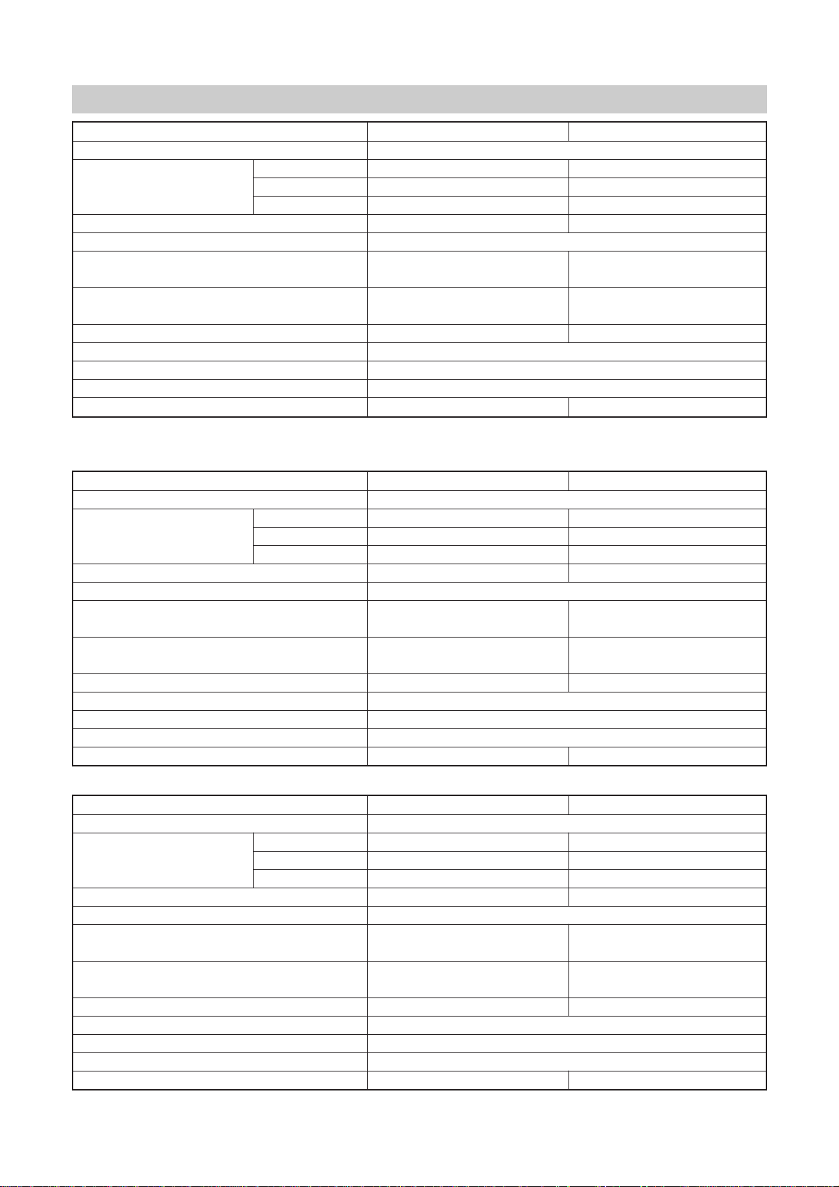
SPECIFICATIONS
- POWER SELECTIONS* : KOG-371R/391R0S : 5 LEVELS.
MODEL
KOG-371G/H/R0S, KOG-374R/5R0S
KOG-391G/H/R0S
POWER SUPPLY 230~, 50Hz SINGLE PHASE WITH EARTHING
MICROWAVE 1200W 1350W
POWER CONSUMPTION GRILL 1050W 1050W
COMBINATION 2200W 2350W
MICROWAVE ENERGY OUTPUT 800W 900W
MICROWAVE FREQUENCY 2450 MHz
OUTSIDE DIMENSIONS(WXHXD) 465X279X360mm 495X294X388mm
(18.3X11.0X14.2 in) (19.5X11.6X15.3 in)
CAVITY DIMENSIONS(WXHXD) 290X220X306mm 320X244X338mm
(11.4X8.7X12.0 in) (12.6X9.6X13.3 in)
NET WEIGHT APPROX. 14Kg(30.9 lbs) APPROX. 16Kg(35.3 lbs)
TIMER 59 min. 90 sec.
FUNCTION SELECTIONS MICROWAVE / GRILL / COMBINATION
POWER SELECTIONS* 10 LEVELS / 5 LEVELS
CAVITY VOLUME 0.7 Cu. Ft. 0.9 Cu. Ft.
MODEL KOG-376T1S KOG-396T1S
POWER SUPPLY 230~, 50Hz SINGLE PHASE WITH EARTHING
MICROWAVE 1200W 1350W
POWER CONSUMPTION GRILL 1050W 1050W
COMBINATION 2200W 1350W
MICROWAVE ENERGY OUTPUT 800W 950W
MICROWAVE FREQUENCY 2450 MHz
OUTSIDE DIMENSIONS(WXHXD) 465X279X370mm 495X294X403mm
(18.3X11.0X14.6 in) (19.5X11.6X15.9 in)
CAVITY DIMENSIONS(WXHXD) 290X220X306mm 320X244X338mm
(11.4X8.7X12.0 in) (12.6X9.6X13.3 in)
NET WEIGHT APPROX. 14Kg(30.9 lbs) APPROX. 16Kg(35.3 lbs)
TIMER 60 min. 00 sec.
FUNCTION SELECTIONS MICROWAVE / GRILL / COMBINATION
POWER SELECTIONS 4 LEVELS
CAVITY VOLUME 0.7 Cu. Ft. 0.9 Cu. Ft.
MODEL KOG-373R0S KOG-393R0S
POWER SUPPLY 230~, 50Hz SINGLE PHASE WITH EARTHING
MICROWAVE 1200W 1350W
POWER CONSUMPTION GRILL 1050W 1050W
COMBINATION 2200W 2350W
MICROWAVE ENERGY OUTPUT 800W 950W
MICROWAVE FREQUENCY 2450 MHz
OUTSIDE DIMENSIONS(WXHXD) 465X279X365mm 495X294X392mm
(18.3X11.0X14.4 in) (19.5X11.6X15.4 in)
CAVITY DIMENSIONS(WXHXD) 290X220X306mm 320X244X338mm
(11.4X8.7X12.0 in) (12.6X9.6X13.3 in)
NET WEIGHT APPROX. 14Kg(30.9 lbs) APPROX. 16Kg(35.3 lbs)
TIMER 59 min. 90 sec.
FUNCTION SELECTIONS MICROWAVE / GRILL / COMBINATION
POWER SELECTIONS 5 LEVELS
CAVITY VOLUME 0.7 Cu. Ft. 0.9 Cu. Ft.
4
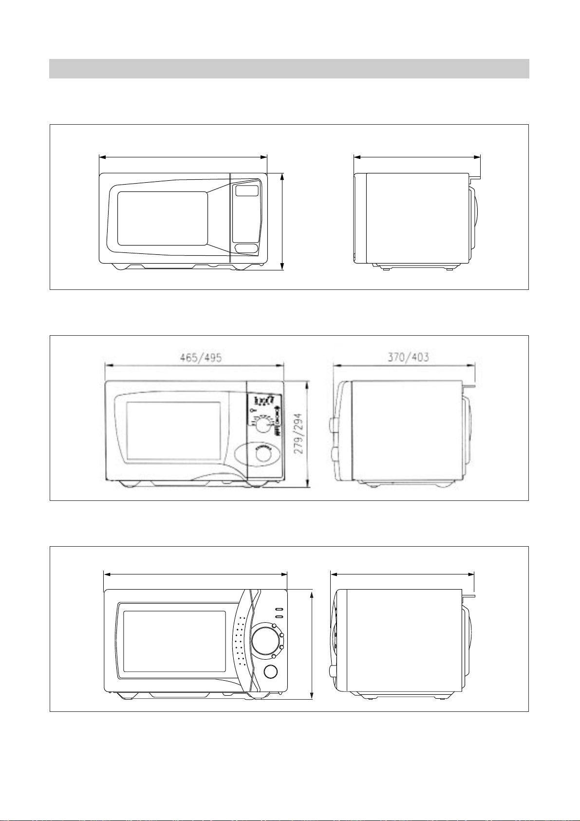
1. OUTER DIMENSION
1) KOG-371G/H0S, KOG-391G/H0S
465/495
279/294
360/388
2) KOG-376T1S, KOG-396T1S
3) KOG-373R0S, KOG-393R0S
365/392465/495
279/294
EXTERNAL VIEW
5
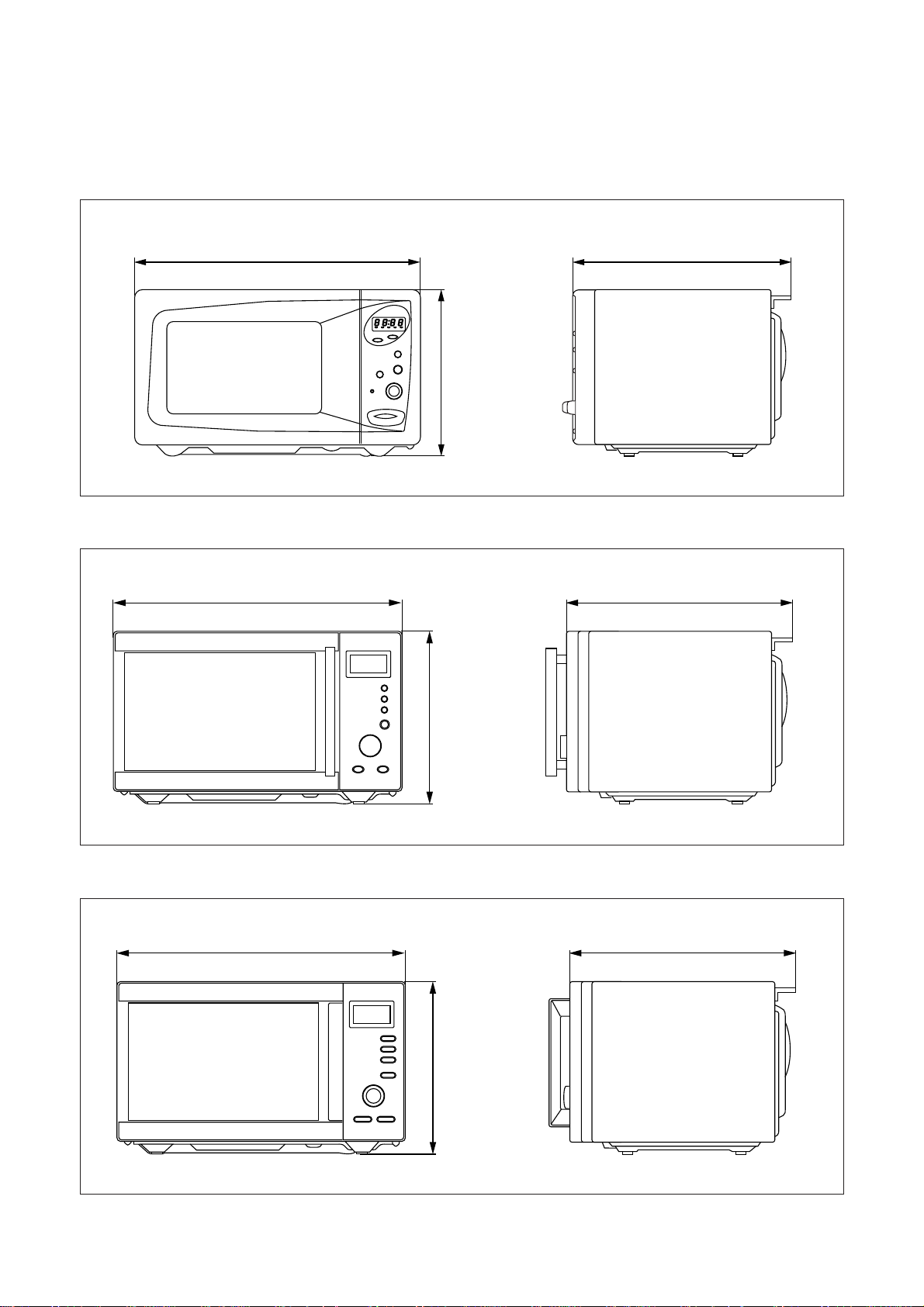
4) KOG-371R0S, KOG-391R0S
465/495
279/294
360/388
5) KOG-374R0S
465
279
360
6) KOG-375R0S
465
279
360
6
1. DOOR SEAL - Door seal maintains the microwave energy within the oven cavity and prevents
microwave leakage.
2. REFLECTOR(Insulator Heater)
3. HEATING ELEMENT
4. OVEN CAVITY
5. SEFETY INTERLOCK SYSTEM
6. DOOR RELEASE BUTTON
- By pushing this button the latch system cut off all circuits and stops the
oven before the door is opened.
7. METAL RACK
8. COUPLER
- This fits over the shaft in the center of the ovens cavity floor. This is to remain in the oven
for all cooking.
9. ROLLER GUIDE - This must always be used for cooking together with the glass cooking tray.
10. GLASS COOKING TRAY - Made of special heat resistant glass. Food in a proper receptacle is
placed on this tray for cooking.
11. DOOR VIEWING SCREEN - Allows viewing of food. The screen is designed so that light can pass
through, but not the microwave.
12. DOOR HOOK - When the door is closed, it will automatically shut off. If the door is opened while the
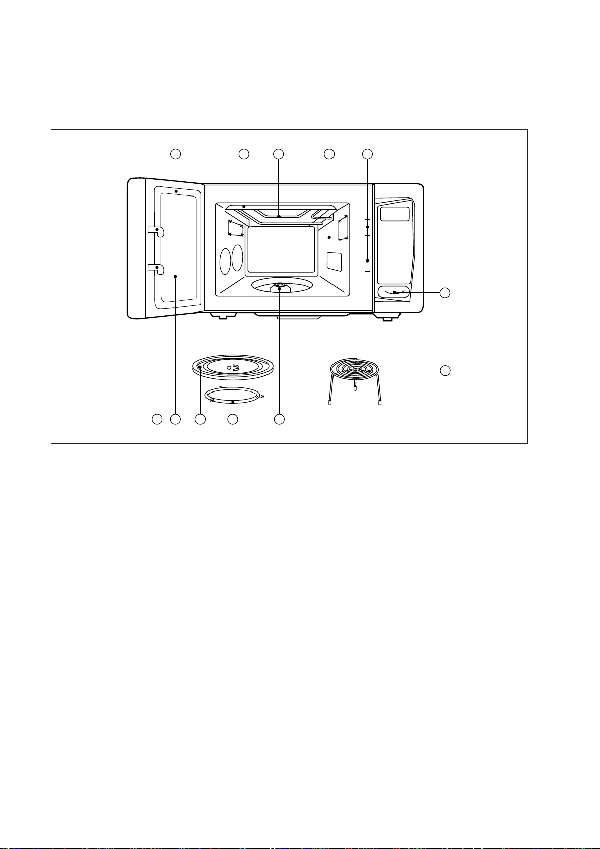
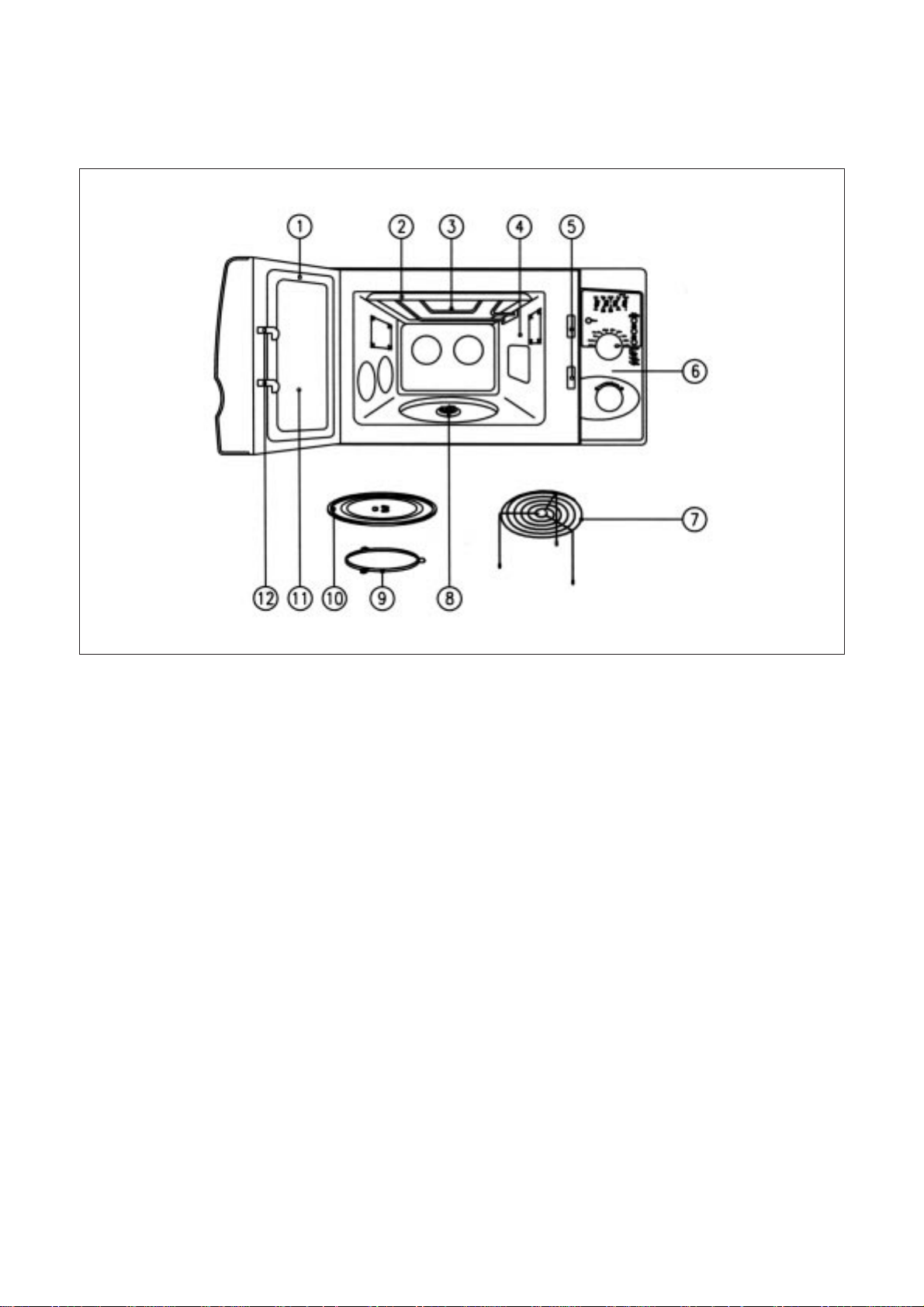
2. FEATURE DIAGRAM
1) KOG-371G/H0S, KOG-391G/H0S
1
2
3 4
7
5
6
8101112 9
7
1. DOOR SEAL - Door seal maintains the microwave energy within the oven cavity and prevents
microwave leakage.
2. REFLECTOR(Insulator Heater)
3. HEATING ELEMENT
4. OVEN CAVITY
5. SEFETY INTERLOCK SYSTEM
6. CONTROL PANEL
7. METAL RACK
8. COUPLER
- This fits over the shaft in the center of the ovens cavity floor. This is to remain in the oven
for all cooking.
9. ROLLER GUIDE - This must always be used for cooking together with the glass cooking tray.
10. GLASS COOKING TRAY - Made of special heat resistant glass. Food in a proper receptacle is
placed on this tray for cooking.
11. DOOR VIEWING SCREEN - Allows viewing of food. The screen is designed so that light can pass
through, but not the microwave.
12. DOOR HOOK - When the door is closed, it will automatically shut off. If the door is opened while the
oven is operating, the magnetron will immediately stop operating.
2) KOG-376T1S, KOG-396T1S
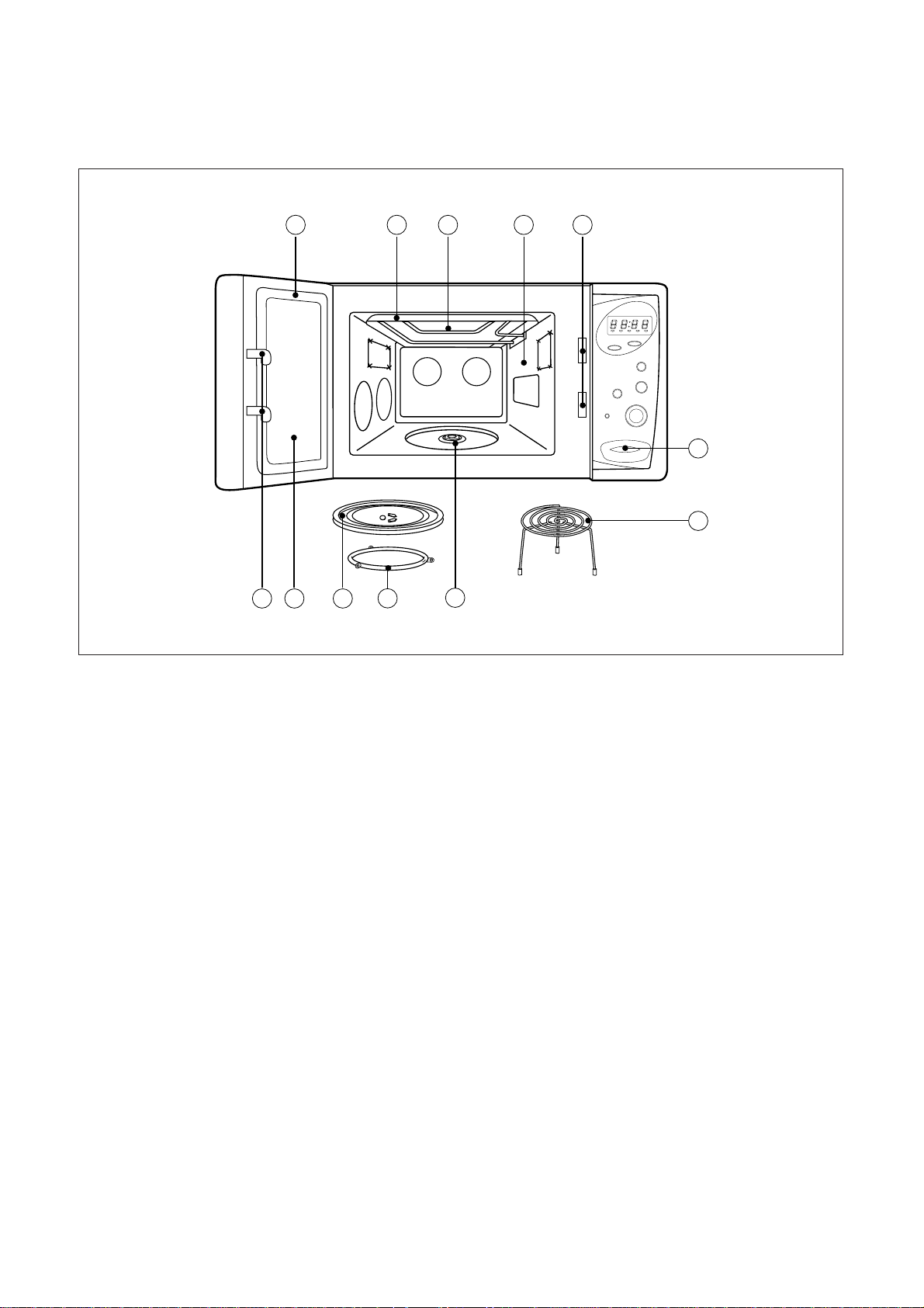
8
1. DOOR SEAL - Door seal maintains the microwave energy within the oven cavity and prevents
microwave leakage.
2. REFLECTOR(Insulator Heater)
3. HEATING ELEMENT
4. OVEN CAVITY
5. SEFETY INTERLOCK SYSTEM
6. CONTROL PANEL
7. DOOR OPENING BUTTON
8. METAL RACK
9. COUPLER
- This fits over the shaft in the center of the ovens cavity floor. This is to remain in the oven
for all cooking.
10. ROLLER GUIDE - This must always be used for cooking together with the glass cooking tray.
11. GLASS COOKING TRAY - Made of special heat resistant glass. Food in a proper receptacle is
placed on this tray for cooking.
12. DOOR VIEWING SCREEN - Allows viewing of food. The screen is designed so that light can pass
through, but not the microwave.
13. DOOR HOOK - When the door is closed, it will automatically shut off. If the door is opened while the
oven is operating, the magnetron will immediately stop operating.
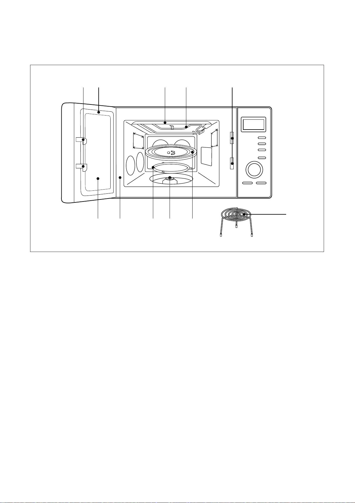
3) KOG-371R0S, KOG-391R0S
1
1112
543
9
8
6
2
10
7

9
1. DOOR SEAL - Door seal maintains the microwave energy within the oven cavity and prevents
microwave leakage.
2. REFLECTOR(Insulator Heater)
3. HEATING ELEMENT
4. OVEN CAVITY
5. SEFETY INTERLOCK SYSTEM
6. METAL RACK
7. COUPLER
- This fits over the shaft in the center of the ovens cavity floor. This is to remain in the oven
for all cooking.
8. ROLLER GUIDE - This must always be used for cooking together with the glass cooking tray.
9. GLASS COOKING TRAY - Made of special heat resistant glass. Food in a proper receptacle is placed
on this tray for cooking.
10. DOOR VIEWING SCREEN - Allows viewing of food. The screen is designed so that light can pass
through, but not the microwave.
11. DOOR HOOK - When the door is closed, it will automatically shut off. If the door is opened while the
oven is operating, the magnetron will immediately stop operating.
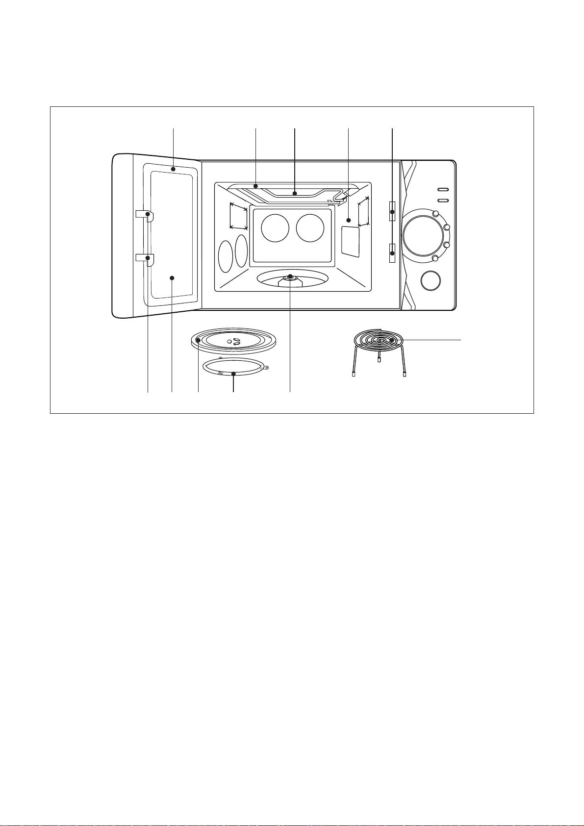
4) KOG-374R0S
q 1 5
98
740
2 3
6
10
1. DOOR SEAL - Door seal maintains the microwave energy within the oven cavity and prevents
microwave leakage.
2. REFLECTOR(Insulator Heater)
3. HEATING ELEMENT
4. OVEN CAVITY
5. SEFETY INTERLOCK SYSTEM
6. METAL RACK
7. COUPLER
- This fits over the shaft in the center of the ovens cavity floor. This is to remain in the oven
for all cooking.
8. ROLLER GUIDE - This must always be used for cooking together with the glass cooking tray.
9. GLASS COOKING TRAY - Made of special heat resistant glass. Food in a proper receptacle is placed
on this tray for cooking.
10. DOOR VIEWING SCREEN - Allows viewing of food. The screen is designed so that light can pass
through, but not the microwave.
11. DOOR HOOK - When the door is closed, it will automatically shut off. If the door is opened while the
oven is operating, the magnetron will immediately stop operating.
5) KOG-375R0S
q 1 5
98
740
2 3
6
11
1. DOOR SEAL - Door seal maintains the microwave energy within the oven cavity and prevents
microwave leakage.
2. REFLECTOR(Insulator Heater)
3. HEATING ELEMENT
4. OVEN CAVITY
5. SEFETY INTERLOCK SYSTEM
6. METAL RACK
7. COUPLER
- This fits over the shaft in the center of the ovens cavity floor. This is to remain in the oven
for all cooking.
8. ROLLER GUIDE - This must always be used for cooking together with the glass cooking tray.
9. GLASS COOKING TRAY - Made of special heat resistant glass. Food in a proper receptacle is placed
on this tray for cooking.
10. DOOR VIEWING SCREEN - Allows viewing of food. The screen is designed so that light can pass
through, but not the microwave.
11. DOOR HOOK - When the door is closed, it will automatically shut off. If the door is opened while the
oven is operating, the magnetron will immediately stop operating.
6) KOG-373R0S, KOG-393R0S
1 5
7
9
0q
2 3 4
6
8
12
1. TIME SET PAD - Used to set the cooking time and the present time.
2. DISPLAY - Cooking time, power level, indicators and present time are displayed.
3. ONE TOUCH - Used to cook or reheat specific quantities of food.
4. AUTO COOK - Used to cook or reheat.
5. MORE - Used to add time to cooking.
6. LESS - Used to remove time from cooking.
7. AUTO DEFROST - Used to defrost foods.(for weight)
8. COMBI - Used to cook COMBI.
9. GRILL - Used to cook GRILL.
10. POWER - Used to set power level.
11. DEFROST
12. KITCHEN TIMER
- Used as a minute timer, to delay the start of cooking, or to set a holding time after
cooking.
13. CLOCK - Used to set clock.
14. STOP/CLEAR - Used to stop the oven operation or to delete the cooking data.
15. START/SPEEDY COOK - Used to start the oven and also used to set a reheat time.
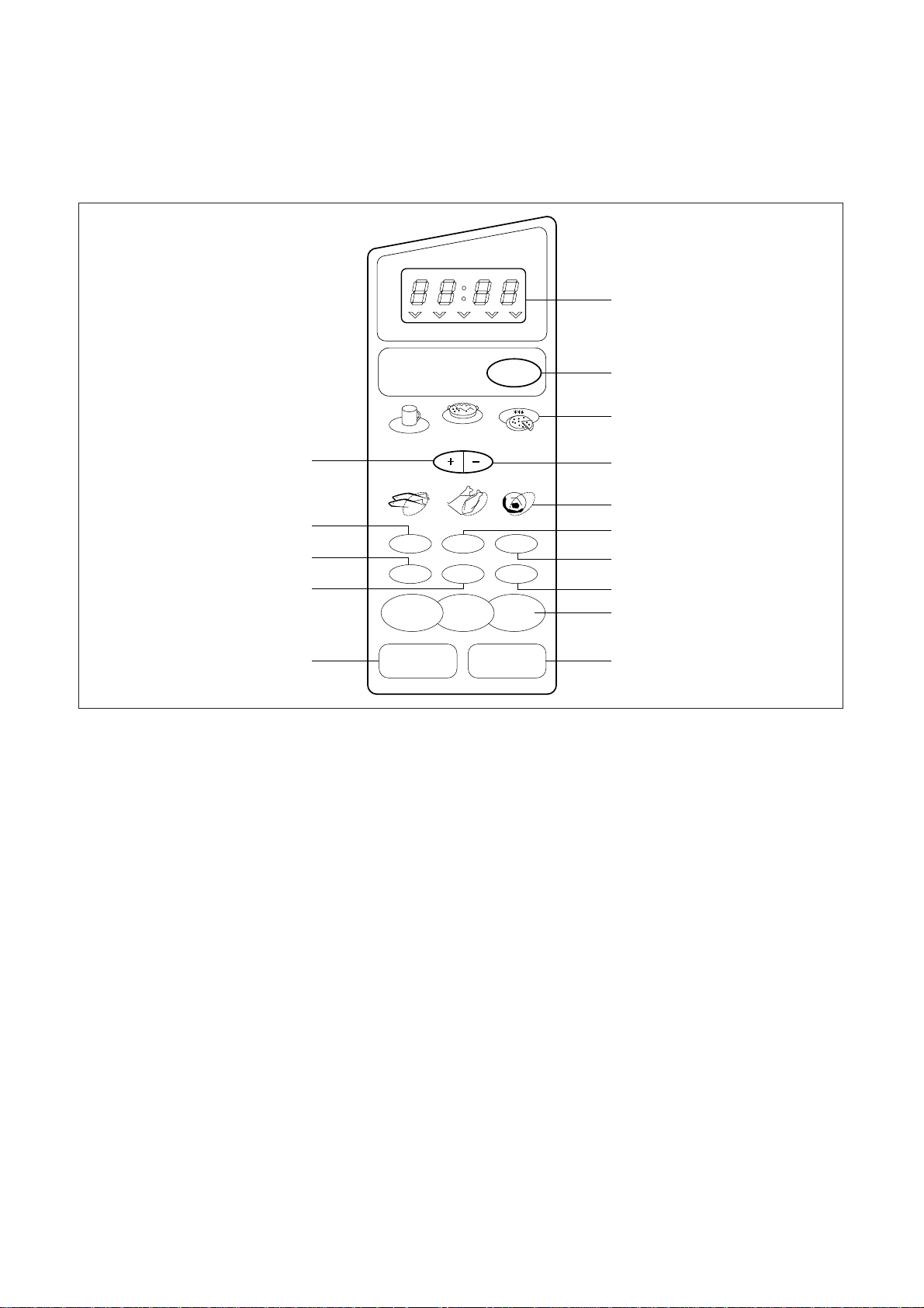
3. CONTROL PANEL
1) KOG-371G0S, KOG-391G0S
M/W Def. Grill Combi Timer/g
Pasta
1. BREAD
2. SOUP
3. BAKED POTATO
4. FRESH VEGETABLE
5. FROZEN VEGETABLE
Auto
Cook
Frozen Pizza
Auto Defrost
Fish Poultry Meat
1min
10S
10min
1M
1hour
10M
STOP/
CLEAR
START/
SPEEDY COOK
2
3
4
7
6
9
1
t
q
e
r
w
0
8
5
Beverage
GRILL DefrostCOMBI
Kitchen
Timer
ClockPower
13
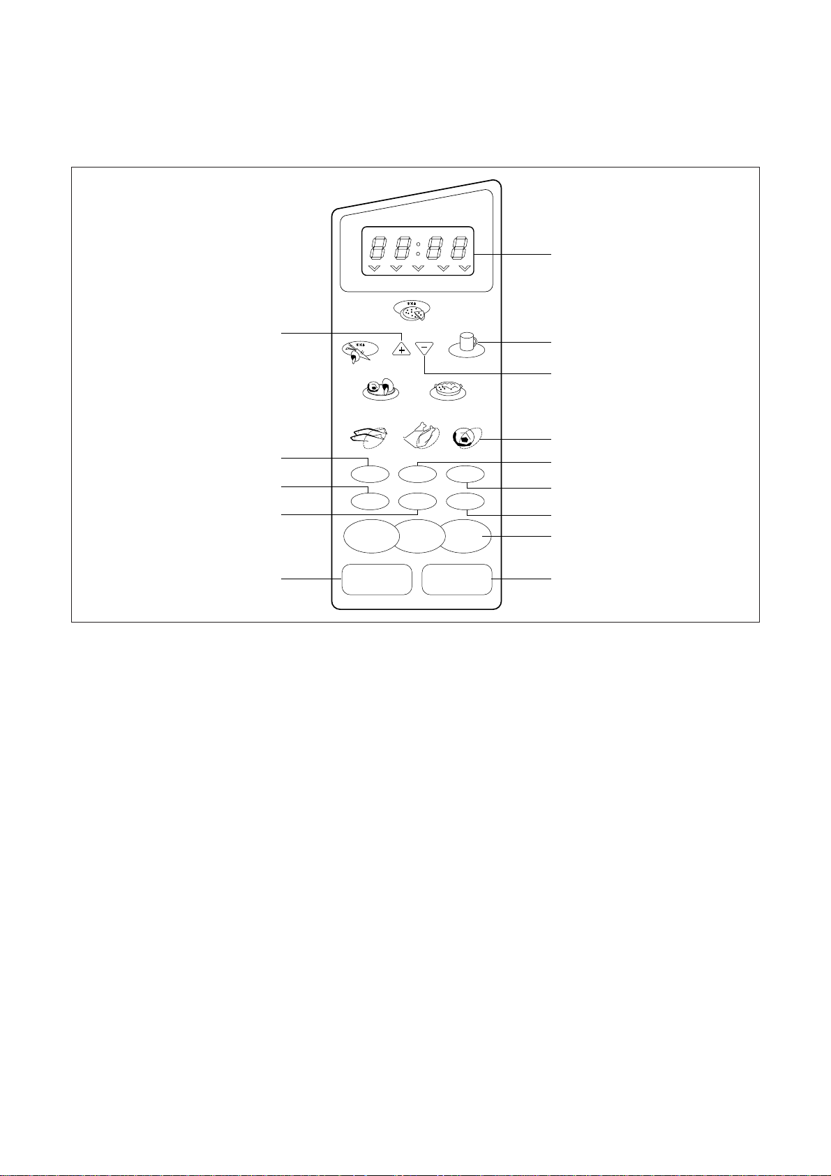
1. TIME SET PAD - Used to set the cooking time and the present time.
2. DISPLAY - Cooking time, power level, indicators and present time are displayed.
3. ONE TOUCH - Used to cook or reheat specific quantities of food.
4. MORE - Used to add time to cooking.
5. LESS - Used to remove time from cooking.
6. AUTO DEFROST - Used to defrost foods.(for weight)
7. COMBI - Used to cook COMBI.
8. GRILL - Used to cook GRILL.
9. POWER - Used to set power level.
10. DEFROST
11. KITCHEN TIMER
- Used as a minute timer, to delay the start of cooking, or to set a holding time after
cooking.
12. CLOCK - Used to set clock.
13. STOP/CLEAR - Used to stop the oven operation or to delete the cooking data.
14. START/SPEEDY COOK - Used to start the oven and also used to set a reheat time.
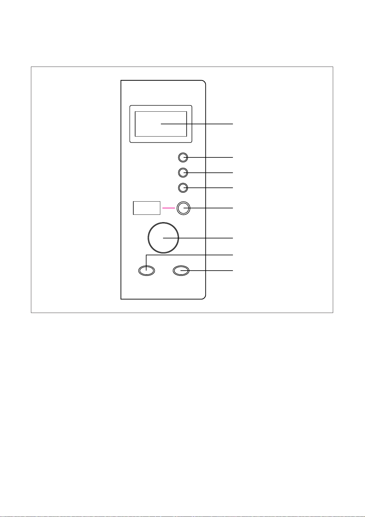
2) KOG-371H0S, KOG-391H0S
M/W Def. Grill Combi Timer/g
Dish Warmer
Fresh Vegetable
Pasta
Frozen Pizza
Auto Defrost
Fish Poultry Meat
1min
10S
10min
1M
1hour
10M
STOP/
CLEAR
START/
SPEEDY COOK
2
3
5
6
8
1
r
0
w
e
q
9
7
4
Beverage
GRILL DefrostCOMBI
Kitchen
Timer
ClockPower
14
1. Display - Cooking time, power level, indicators and present time are displayed.
2. Clock - Used to set clock.
3. Start/Easy Cook - Used to start operation, also for easy start (each press adds 30 seconds microwave
cooking time).
4. Stop/Clear - Used to stop the operation or to delete the cooking data.
5. Auto Cook - Used to cook using a program.
6. Knob - Turm to set the cooking menu and select a microwave power level.
7. Knob - Dial for setting time and weight.(You can also extend the time of the current operation by 1
minute by turning the dial knob, except defrosting)
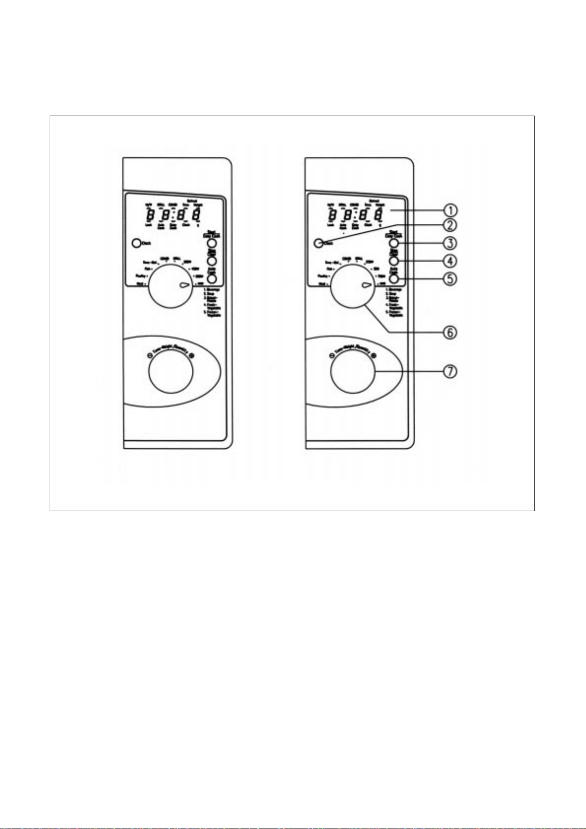
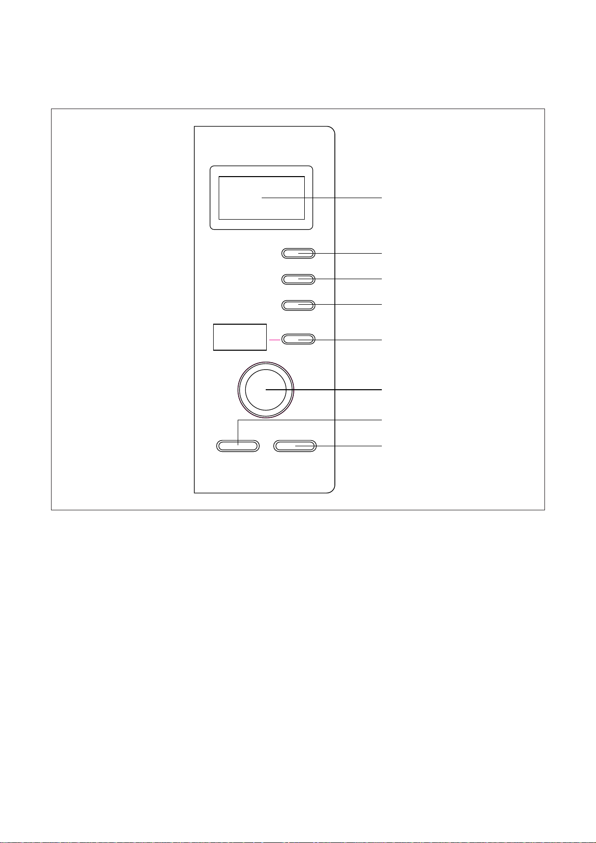
3) KOG-376T1S, KOG-396T1S
15
1. Display - Cooking time, power level, indicators and present time are displayed.
2. Grill/Combi - Used to cook GRILL or COMBI.
3. Power/Def - Used to set power level and DEFROST.
4. Auto cook - Used to cook using a program or to reheat.
5. Start / Easy cook - Used to start the oven operation and also increase the reheat time by 30 seconds.
6. Stop / Clear - Used to stop the oven operation or to erase all entries.
7. Clock - Used to set clock.
8. Dial Knob - Used to set the time and weight.
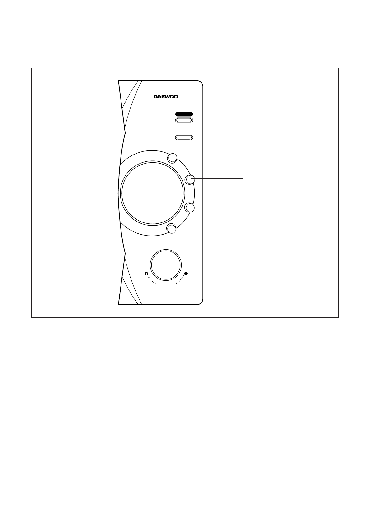
4) KOG-371R0S, KOG-391R0S
M/W
Grill/Combi
Power/Def.
1. Dinner plate
2. Soup
3. Beverage
4. Fresh vegetable
Auto cook
Start/
Easy cook
Weight/
Time
Stop/Clear
Clock
DEF. Grill Combi g
1
3
6
7
2
4
5
8
16
1. Display - Cooking time, power level, indicators and present time are displayed.
2. Grill/Combi - Used to cook GRILL or COMBI.
3. Power/Def - Used to set power level and DEFROST.
4. Auto cook - Used to cook using a program or to reheat.
5. Start / Easy cook - Used to start the oven operation and also increase the reheat time by 30 seconds.
6. Stop / Clear - Used to stop the oven operation or to erase all entries.
7. Clock - Used to set clock.
8. Dial Knob - Used to set the time and weight.
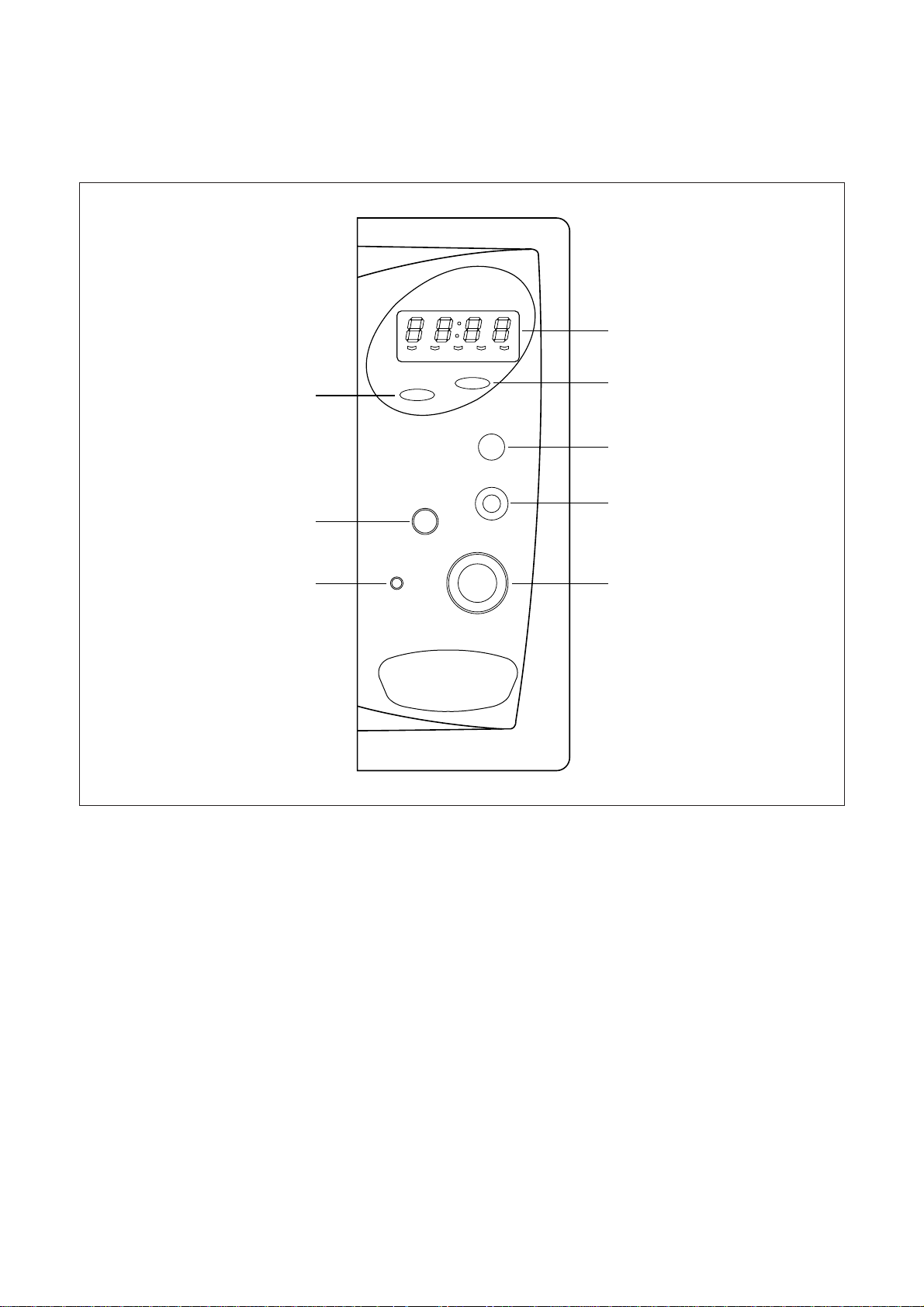
4) KOG-374R0S
W
e
i
g
h
t
/
T
i
m
e
Power/Def
Grill/Combi
Clock
1. Dinner Plate
2. Soup
3. Beverage
4. Fresh Vegetable
Auto Cook
Stop/Clear Start/Easy Cook
1
3
2
7
4
8
6
5
17
1. Display - Cooking time, power level, indicators and present time are displayed.
2. Grill/Combi - Used to cook GRILL or COMBI.
3. Power/Def - Used to set power level and DEFROST.
4. Auto cook - Used to cook using a program or to reheat.
5. Start / Easy cook - Used to start the oven operation and also increase the reheat time by 30 seconds.
6. Stop / Clear - Used to stop the oven operation or to erase all entries.
7. Clock - Used to set clock.
8. Dial Knob - Used to set the time and weight.
4) KOG-375R0S
W
e
i
g
h
t
/
T
i
m
e
Power/Def
Grill/Combi
Clock
1. Dinner Plate
2. Soup
3. Beverage
4. Fresh Vegetable
Auto Cook
Stop/Clear Start/Easy Cook
1
3
2
7
4
8
6
5
18
1. Display - Cooking time, power level, indicators and present time are displayed.
2. Grill/Combi - Used to cook grill/combi.
3. Power/Def - Used to set power level. Used to defrost foods by weight or time.
4. Auto cook - Used to cook using a program or to reheat.
5. Start / Easy cook - Used to start the oven operation and also increase the reheat time by 30 seconds.
6. Stop / Clear - Used to stop the oven operation or to erase all entries.
7. Clock - Used to set clock.
8. Dial Knob - Used to set the time and weight.
5) KOG-373R0S, KOG-393R0S
W
e
i
g
h
-
T
i
m
e
M/W DEF. Grill Combi
Power/
Defrost
Grill/Combi
1. Dinner Plate
2. Soup
3. Beverage
4. Fresh Vegetable
Auto cook
Clock
Stop/
Clear
Start/
Easy cook
g
KOG-373R
4
2
3
7
1
6
5
8

19
INSTALLATION
1. Steady, flat location
This microwave oven should be set on a steady, flat surface.
This microwave oven is designed for counter top use only.
2. Leave space behind and side
All air vents should be kept a clearance. If all vents are covered during operation, the oven may overheat and,
eventually, cause failure.
3. Away from radio and TV sets
Poor television reception and radio interference may result if the oven is located close to a TV, radio, antenna or
feeder and so on.
Position the oven as far from them as possible.
4. Away from heating appliances and water taps
Keep the oven away from hot air, steam or splash when choosing a place to position it, or the insulation might be
adversely affected and breakdowns occur.
5. Power supply
• Check your local power source.
This microwave oven requires a current of approximately 11 amperes, 230 Volts, 50 Hz.
• Power supply cord is about 1.4 meters long.
• The voltage used must be the same as specified on this oven. Using a higher voltage may result in a fire or other
accident causing oven damage. Using low voltage will cause slow cooking. We are not responsible for damage
resulting from use of this oven with a voltage of ampere fuse other than those specified.
• This appliance is supplied with cable of special type, which, if damaged, must be reparied with cable of same type.
Such a cable can be purchased from DAEWOO and must be installed by Qualified Person.
6. Examine the oven after unpacking for any damage such as:
A misaligned door, broken door or a dent in cavity.
If any of the above are visible, DO NOT INSTALL, and notify dealer immediately.
7. Do not operate the oven if it is colder than room temperature
(This may occur during delivery in cold weather.) Allow the oven to become room temperature before operating.
EARTHING INSTRUCTIONS
This appliance must be earthed. In the event of an electrical short circuit, earthing reduces the risk of the electric
shock by providing an escape wire for the electric current. This appliance is equipped with a cord having a
earthing wire with a earthing plug. The plug must be plugged into an outlet that is properly installed and earthed.
WARNING :
Improper use of the earthing plug can result in a risk of electric shock. Consult a qualified electrician or
serviceman if the earthing instructions are not completely understood, or if doubt exists as to whether
the appliance is properly earthed, and either : If it is necessary to use an extension cord, use only a 3-
wire extension cord that has a 3-blade earthing plug, and a 3-slot receptacle that will accept the plug on
the appliance. The marked rating of the extension cord should be equal to or greater than the electrical
rating of the appliance, or Do not use an extension cord.
20
1. Connect the main lead to an electrical outlet.
2. After placing the food in a suitable container, open the oven door and put it on the glass tray. The glass tray must
always be in place during cooking.
3. Close the door securely.
4. When the oven door is opened, the light turns off.
5. The oven door can be opened at any time during operation by touching the door release button on the control
panel.
The oven will automatically shut off. To restart the oven, close the door and then touch START.
6. Each time a pad or a button is touched, a BEEP will sound to acknowledge the touch.
7. The oven automatically cook on full power unless set to a lower power level.
8. The display will show : 0 when the oven is plugged in.
9. Time clock returns to the present time when the cooking time ends.
10. When the STOP/CLEAR pad or button is touched during the oven operation, the oven stops cooking and all
information retained.
To erase all infomation (except the present time), touch the STOP/CLEAR pad once more. If the oven door is
opened during the oven operation, all information is retained.
11. If the START pad is touched and the oven does not operate, check the area between the door and door is closed
securely. The oven will not start cooking under the door is completely closed or the program has been reset.
12. When using the GRILL or COMBI mode;
• Do not open the door so often, the temperature inside the oven derease and the cooking may not be completed
in setting time.
• Never touch the oven window and metal interior of the oven when taking food in and out, because the
temperature inside the oven and door is very high.
• When using these modes, be careful as the tray will be hot to touch, use oven gloves or pot holders while
handling tray.
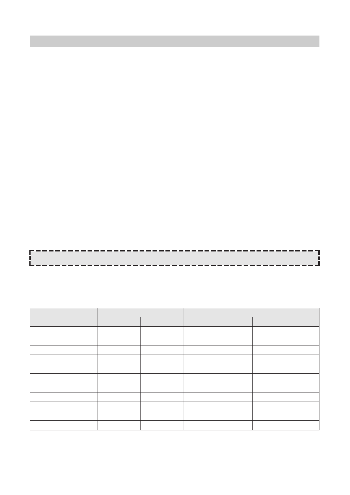
Wattage output chart
The power level is set by pressing the power pad. The chart shows the display, the power level and the percentage
of power.
*A : KOG-371G/H0S, KOG-391G/H0S
*B : KOG-371R0S, KOG-391R0S, KOG-374R/375R0S
Touch Power pad Power level (Display) Approximate Percentage of Power
or button A B A B
Once P-H1 P-HI 100% 100%
Twice P-90 P-80 90% 80%
3 times P-80 P-60 80% 60%
4 times P-70 P-40 70% 40%
5 times P-60 P-20 60% 20%
6 times P-50 — 50% —
7 times P-40 — 40% —
8 times P-30 — 30% —
9 times P-20 — 20% —
10 times P-10 — 10% —
11 times P-00 — 0% —
OPERATION AND FUNCTIONS
Make the oven is properly installed and plugged into the electrical outlet.
21
DISASSEMBLY AND ASSEMBL Y
Cautions to be observed when trouble shooting
Unlike many other appliances, the microwave oven is a high-voltage, high-current equipment.
It is completely safety during normal operation. However, carelessness in servicing the oven
can result in an electric shock or possible danger from a short circuit.
You are asked to observe the following precautions carefully.
1. Always remove the power plug from the outlet before servicing.
2. Use an insulated screwdriver and ware rubber gloves when servicing the high voltage side.
3. Discharge the high voltage capacitor before touching any oven components or wiring.
(1) Check the earthed.
Do not operate on a two wire extension cord.
The microwave oven is designed to be used with earthed.
It is imperative, therefore, to makes sure it is earthed properly before
beginning repair work.
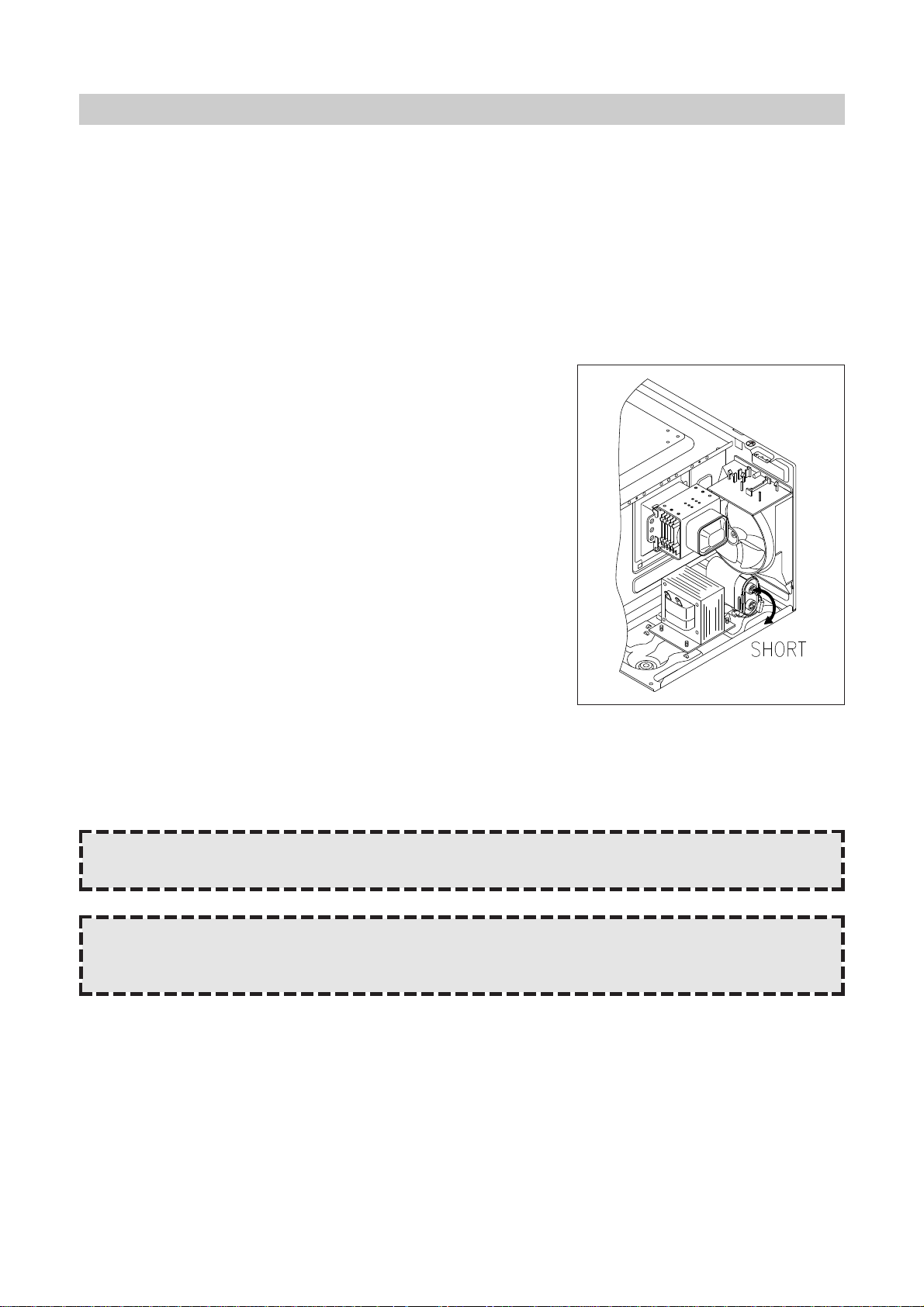
(2) Warning about the electric charge in the high voltage capacitor.
For about 30 seconds after the operation stopped, and electric
charge remains in the high voltage capacitor. When replacing or
checking parts, short between oven chassis and the negative high
terminal of the high voltage capacitor, by using a properly insulted
screwdriver to discharge.
4. When the 15A fuse is blown out due to the operation of the monitor
switch; replace primary interlock switch, secondary interlock switch
and interlock monitor switch.
Refer to next page for the necessary adjustment.
5. After repair or replacement of parts, make sure that the screws are properly tightened, and all electrical
connections are tightened.
6. Do not operate without cabinet.
CAUTION : Service personnel should remove their watches whenever working close to or replacing the
magnetron.
WARNING : When servicing the appliance, need a care of touching or replacing high potential parts because
of electrical shock or exposing microwave. These parts are as follows-HV Transformer,
Magnetron, HV Capacitor, HV Diode. HV Fuse.
22
DISASSEMBLY AND ASSEMBL Y
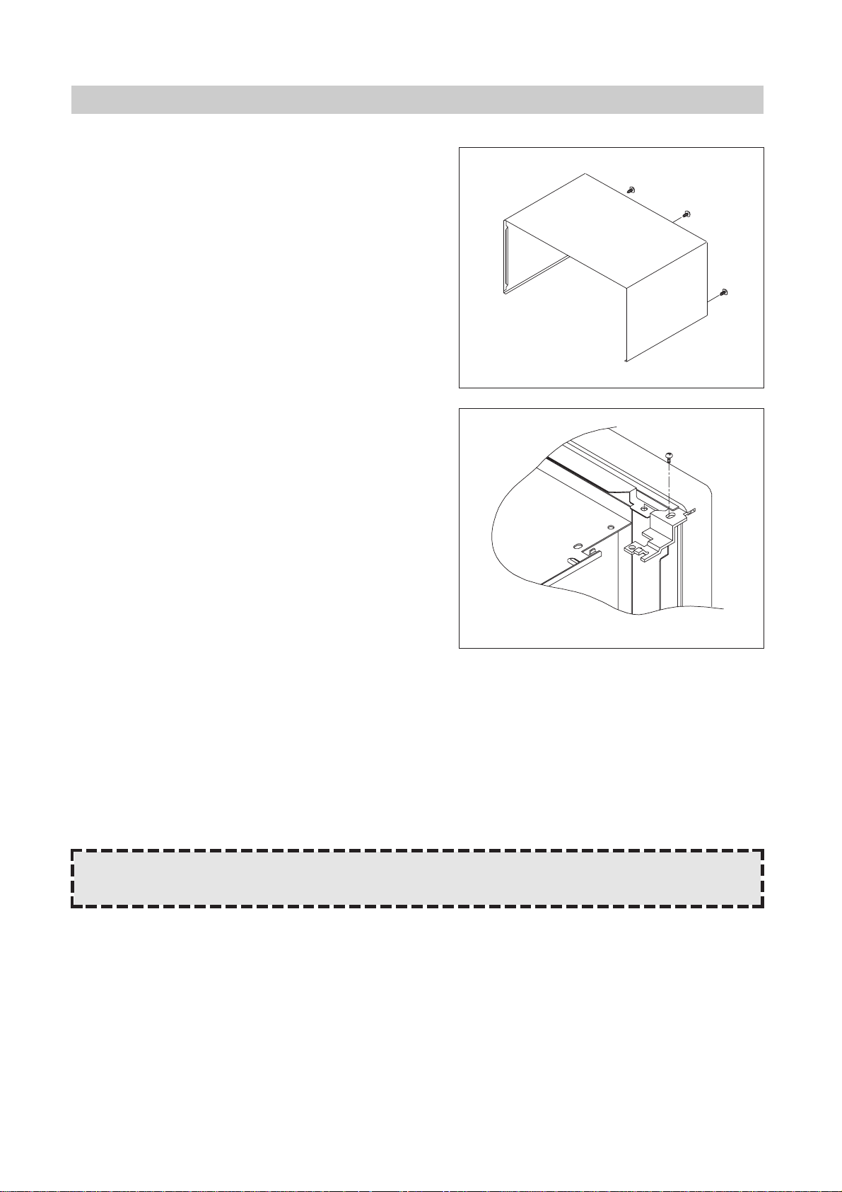
1. To remove cabinet.
1) Remove three screws on cabinet back.
2) Push the cabinet backward.
2. To remove door assembly.
1)
Remove a screw which secure the stopper hinge top.
2) Remove the door assembly from top plate of cavity.
3) Reverse the above for reassembly.
NOTE : After replacing the door assembly, perform a check of correct alignment with the hinge and cavity
front plate.
23
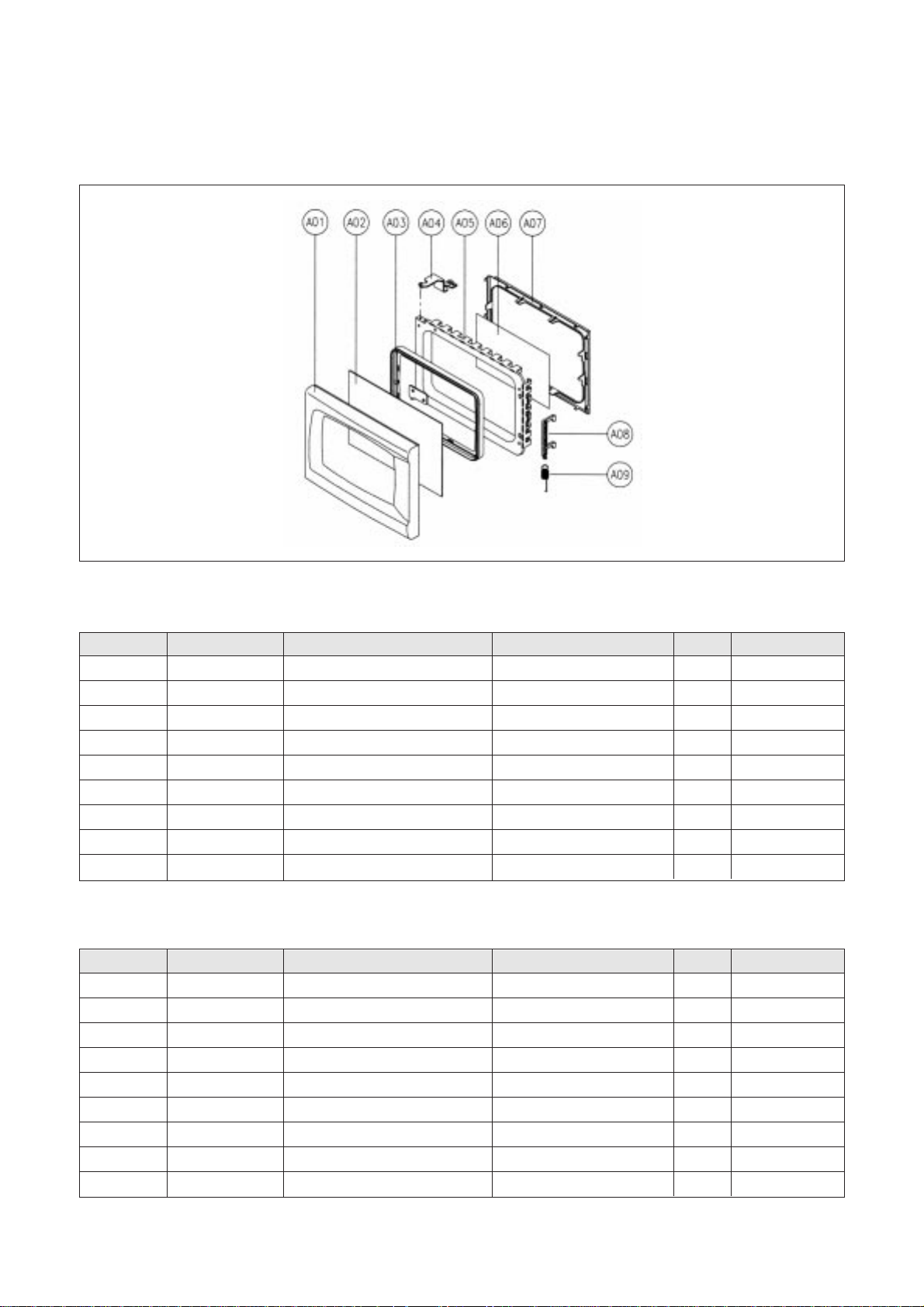
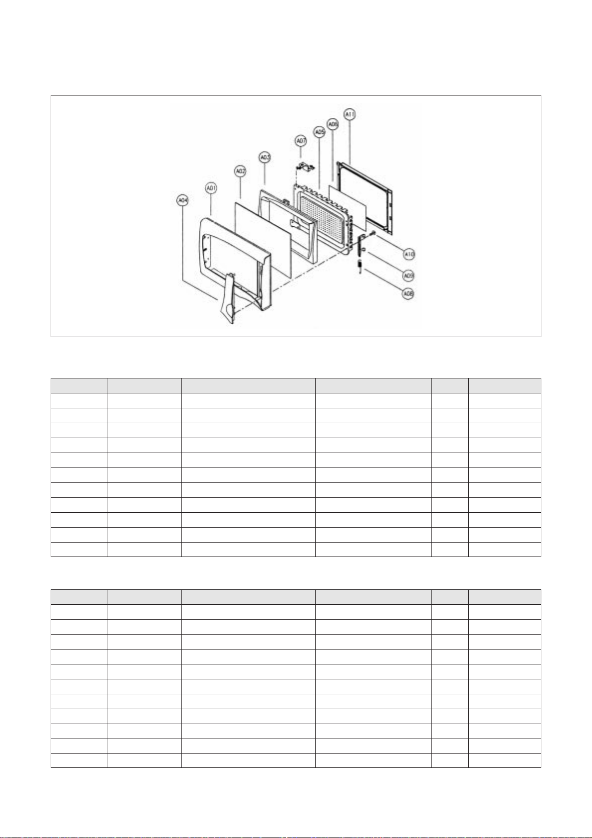
3. To remove door parts.
(1) KOG-371G0S/371H0S/371R0S
(2) KOG-391G0S/391H0S/391R0S
REF. NO PART CODE PART NAME DESCRIPTION QTY REMARK
A01 3512204100 FRAME DOOR ABS XR-401 H-2938 1
A02 3517003150 BARRIER-SCREEN*0 ACRYL 1
A03 3515304410 SUPPORTER BARR-S*0 PP 1
A04 3515204100 STOPPER HINGE *T AS KOR-63150S 1
A05 3511705620 DOOR WELD AS KOR-81250S 1
A06 3517002900 BARRIER-SCREEN *I POLYESTER T0.1 1
A07 3512300400 GASKET DOOR PP 1
A08 3513100700 HOOK POM 1
A09 3515101300 SPRING HOOK PW1 1
REF. NO PART CODE PART NAME DESCRIPTION QTY REMARK
A01 3512203800 FRAME DOOR ABS XR-401 H-2938 1
A02 3517003050 BARRIER-SCREEN*0 ACRYL 1
A03 3515304610 SUPPORTER BARR-S*0 PP 1
A04 3515204100 STOPPER HINGE *T AS KOR-63150S 1
A05 3511705500 DOOR WELD AS KOR-61150S 1
A06 3517002800 BARRIER-SCREEN *I POLYESTER T0.1 1
A07 3512300200 GASKET DOOR PP 1
A08 3513100700 HOOK POM 1
A09 3515101300 SPRING HOOK PW1 1
✔ Caution:
In this Service Manual, some parts can be changed for improving, their performance without notice in the parts list. So, if you need the
latest parts information, please refer to PPL(Parts Price List) in Service information Center(http://svc.dwe.co.kr)
24
1) Remove the gasket door from door plate.
2) Remove the barrier screen inner from door plate.
3) Remove the door frame from door plate.
4) Remove the stopper hinge top from door plate.
5) Remove the spring and the hook.
6) Remove the supporter barrier screen outer from door frame.
7) Remove the barrier screen outer from door frame.
8) Remove the above steps for reassembly.
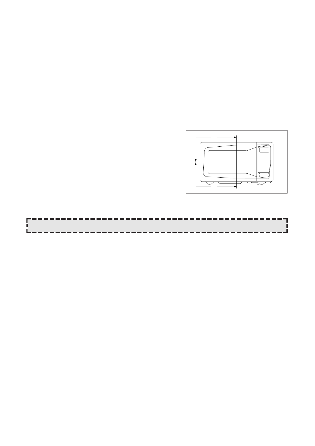
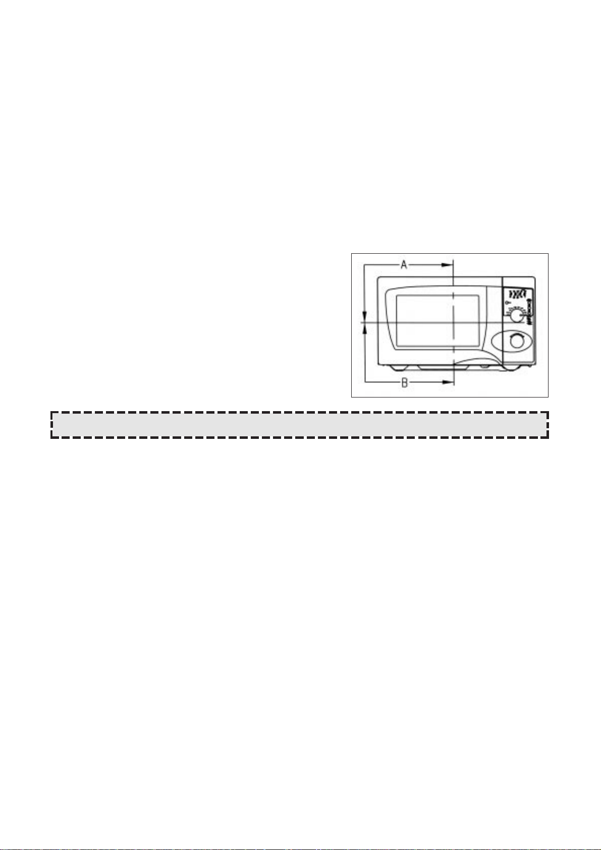
4. Method to reduce the gap between the door seal and the oven front surface.
1) To reduce gap located on part ‘A’.
• Loosen a screw on stopper hinge top, and then push the
door to contact the door seal to oven front surface.
• Tighten a screw.
2) To reduce gap located on part ‘B’.
• Loosen two screws on stopper hinge under, and then push
the door to contact the door seal to oven front surface.
• Tighten two screws.
A
B
NOTE : A small gap may be acceptable if the microwave leakage does not exceed 4mW/cm
2
.
25
(3) KOG-376T1S
(4) KOG-396T1S
REF. NO PART CODE PART NAME DESCRIPTION QTY REMARK
A01 3512203830 FRAME DOOR ABS 1
A02 3517005610 BARRIER-SCREEN*0 PMMA 1.5t 1
A03 3515306500 SUPPORTER BARR-S*0 ABS 1
A04 3511603800 DECORATOR DOOR ABS 1
A05 3511706100 DOOR PAINTING AS KOR-61150S 1
A06 3517002800 BARRIER-SCREEN *I KOR-61150S PE 0.1t 1
A07 3515204110 STOPPER HINGE *T AS KOR-636T1S SCP T2.6 1
A08 3515101310 SPRING HOOK HSW-3 1
A09 3513100730 HOOK KOR-6325 POM 1
A11 7122401211 SCREW TAPPING T2S TRX 4X12 MFZN
A12 3512300200 GASKET DOOR KOR-61150S PP 1
REF. NO PART CODE PART NAME DESCRIPTION QTY REMARK
A01 3512204130 FRAME DOOR ABS 1
A02 3517005710 BARRIER-SCREEN*0 PMMA 1.5t 1
A03 3515306600 SUPPORTER BARR-S*0 ABS 1
A04 3511604000 DECORATOR DOOR ABS 1
A05 3511711800 DOOR PAINTING AS KOR-866T1S 1
A06 3517006000 BARRIER-SCREEN *I KOR-866T1S PE 0.1t 1
A07 3515204110 STOPPER HINGE *T AS KOR-636T1S SCP T2.6 1
A08 3515101310 SPRING HOOK HSW-3 1
A09 3513100730 HOOK KOR-6325 POM 1
A11 7122401211 SCREW TAPPING T2S TRX 4X12 MFZN 1
A12 3512302000 GASKET DOOR KOR--86671S PP 1
✔ Caution:
In this Service Manual, some parts can be changed for improving, their performance without notice in the parts list. So, if you need the
latest parts information, please refer to PPL(Parts Price List) in Service information Center(http://svc.dwe.co.kr)
26
1) Remove the gasket door from door plate.
2) Remove a screw which secure the door plate and door frame.
3) Remove the door frame from door plate.
4) Remove the stopper hinge top from door plate.
5) Remove the spring and the hook.
6) Remove the supporter barrier screen outer from door frame.
7) Remove the barrier screen outer from door frame.
8) Remove the decorater door rrom door frame.
9) Reverse the above steps for reassembly.
4. Method to reduce the gap between the door seal and the oven front surface.
1) To reduce gap located on part ‘A’.
• Loosen a screw on stopper hinge top, and then push the
door to contact the door seal to oven front surface.
• Tighten a screw.
2) To reduce gap located on part ‘B’.
• Loosen two screws on stopper hinge under, and then push
the door to contact the door seal to oven front surface.
• Tighten two screws.
NOTE : A small gap may be acceptable if the microwave leakage does not exceed 4mW/cm
2
.
27
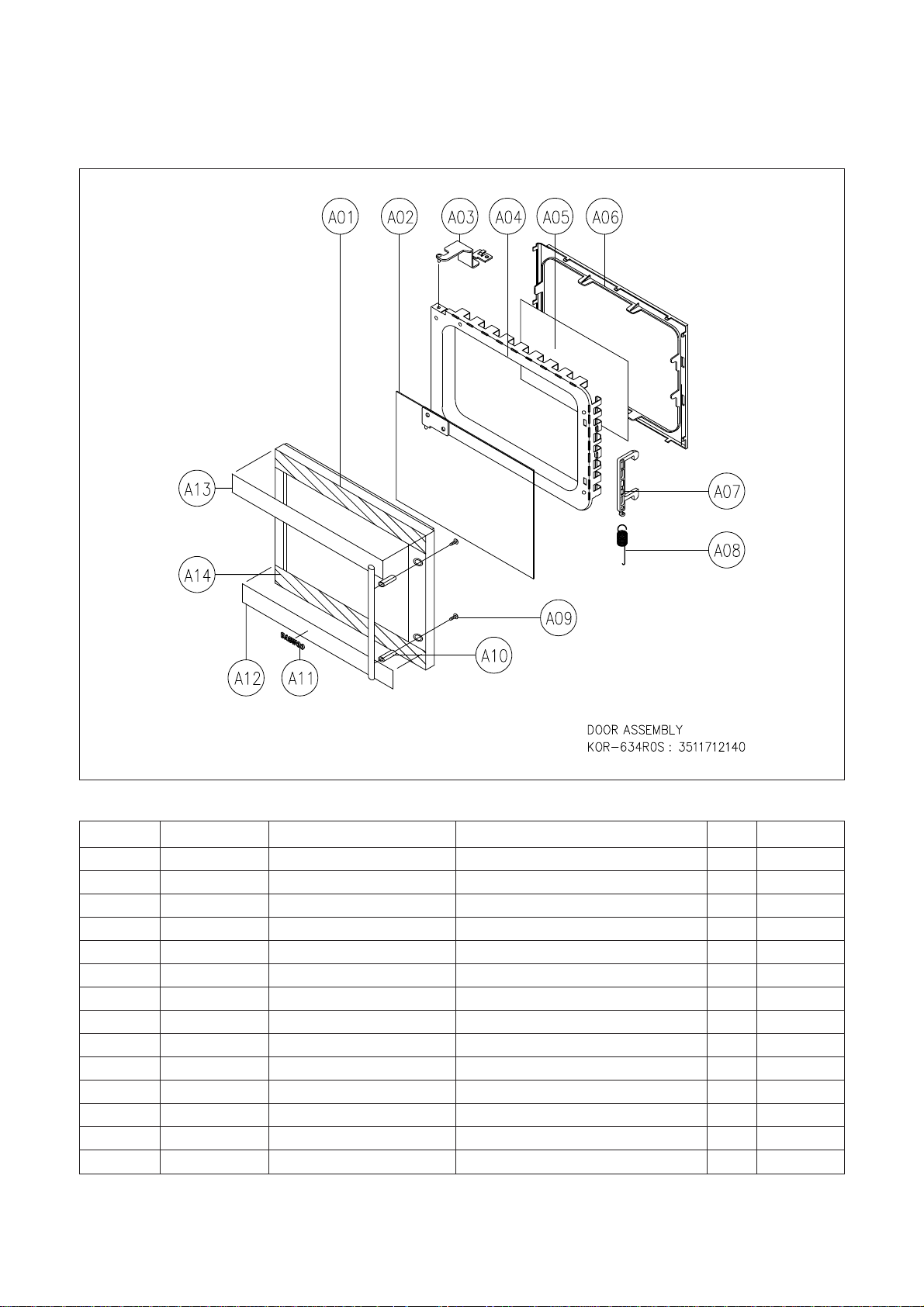
REF NO. PART CODE PART NAME DESCRIPTION Q’TY REMARK
A01 3512203850 FRAME DOOR ABS XR-401, H-2938 1
A02 3517005620 BARRIER-SCREEN*O TEMP GLASS T3.2 1
A03 3515204100 STOPPER HINGE*T AS KOR-63150S 1
A04 3511706120 DOOR PAINTING AS KOR-634R0S 1
A05 3517002800 BARRIER-SCREEN*I PE 0.1T 1
A06 3512300200 GASKET DOOR PP 1
A07 3513100730 HOOK POM BLACK 1
A08 3515101310 SPRING HOOK HSW-3 1
A09 7001503311 SCREW MACHINE PAN 5X33 MFZN 2
A10 3512603210 HANDLE DOOR STEEL NI + CR 1
A11 3511601500 DECORATOR LOGO AL T1.5 1
A12 3511604610 DECORATOR DOOR*U STS T0.6 1
A13 3511604600 DECORATOR DOOR*T STS T0.6 1
A14 3516003940 SPECIAL DOUBLE TAPE H0 SUNG 550M 1
(5) KOG-374R0S
✔ Caution:
In this Service Manual, some parts can be changed for improving, their performance without notice in the parts list. So, if you need the
latest parts information, please refer to PPL(Parts Price List) in Service information Center(http://svc.dwe.co.kr)
28
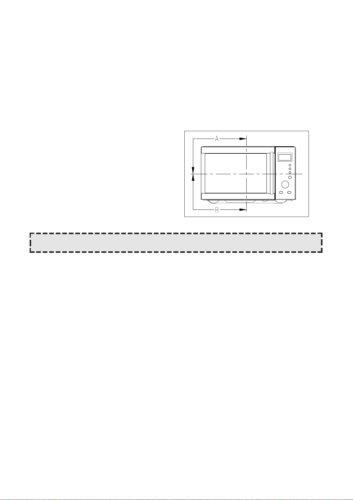
4. Method to reduce the gap between the door seal and the oven front surface.
(1) To reduce gap located on part ‘A’
• Loosen two screws on stopper hinge top, and then
push the door to contact the door seal to oven front
surface.
• Tighten two screws.
(2) To reduce gap located on part ‘B’
• Loosen two screws on stopper hinge under, and
then push the door to contact the door seal to oven
front surface.
• Tighten two screws.
(1) Remove the gasket door from door weld as.
(2) Remove the barrier screen inner from weld as.
(3) Remove the door frame from door weld as.
(4) Remove the stopper hinge top from door weld as.
(5) Remove the spring and the hook.
(6) Remove the barrier screen outer from door frame.
(7) Reverse the above steps for reassembly.
NOTE : A small gap may be acceptable if the microwave leakage does not exceed 4mW/cm
2
.
29
REF NO. PART CODE PART NAME DESCRIPTION Q’TY REMARK
A01 3512203850 FRAME DOOR ABS XR-401, H-2938 1
A02 3517005620 BARRIER-SCREEN*O TEMP GLASS T3.2 1
A03 3515204100 STOPPER HINGE*T AS KOR-63150S 1
A04 3511706120 DOOR PAINTING AS KOR-634R0S 1
A05 3517002800 BARRIER-SCREEN*I PE 0.1T 1
A06 3512300200 GASKET DOOR PP 1
A07 3513100730 HOOK POM BLACK 1
A08 3515101310 SPRING HOOK HSW-3 1
A09 7122401611 SCREW TAPPING T2SN TRS 4X16 MFZN 2
A10 3512603300 HANDLE DOOR *U ABS XR-401, H-2938 1
A11 3512603400 HANDLE DOOR *T STS T0.6 1
A12 3511601500 DECORATOR LOGO AL T1.5 1
A13 3511604610 DECORATOR DOOR*U STS T0.6 1
A14 3511604600 DECORATOR DOOR*T STS T0.6 1
A15 3516003940 SPECIAL DOUBLE TAPE H0 SUNG 550M T0.15 27MM 1
(6) KOG-375R0S
(1) Remove the gasket door from door plate.
(2) Remove the barrier screen inner from door plate.
(3) Remove the door frame from door plate.
(4) Remove the stopper hinge top from door plate.
(5) Remove the spring and the hook.
(6) Remove the barrier screen outer from door frame.
(7) Reverse the above steps for reassembly.
✔ Caution:
In this Service Manual, some parts can be changed for improving, their performance without notice in the parts list. So, if you need the
latest parts information, please refer to PPL(Parts Price List) in Service information Center(http://svc.dwe.co.kr)
 Loading...