


Daewoo G420E, G424E, G15S-2, G18S-2, G20SC-2 Service Manual
...SB4136E00
May. 2004
Service Manual
G420E/G424E Tier  LP Engine
Lift Trucks
G15S-2, G18S-2, G20SC-2 GC15S-2, GC18S-2, GC20SC-2 With G420E Tier  LP Engine
G20E-3, G25E-3, G30E-3, G32E-3 GC20E-3, GC25E-3, GC30E-3, GC32E-3 with G424E Tier  LP Engine

Important Safety Information
Most accidents involving product operation, maintenance and repair are caused by failure to observe basic safety rules or precautions. An accident can often be avoided by recognizing potentially hazardous situations before an accident occurs. A person must be alert to potential hazards. This person should also have the necessary training, skills and tools to perform these functions properly.
Read and understand all safety precautions and warnings before operating or performing lubrication, maintenance and repair on this product.
Basic safety precautions are listed in the “Safety” section of the Service or Technical Manual. Additional safety precautions are listed in the “Safety” section of the owner/operation/maintenance publication.
Specific safety warnings for all these publications are provided in the description of operations where hazards exist. WARNING labels have also been put on the product to provide instructions and to identify specific hazards. If these hazard warnings are not heeded, bodily injury or death could occur to you or other persons. Warnings in this publication and on the product labels are identified by the following symbol.
 WARNING
Improper operation, lubrication, maintenance or repair of this product can be dangerous and could result in injury or death.
Do not operate or perform any lubrication, maintenance or repair on this product, until you have read and understood the operation, lubrication, maintenance and repair information.
Operations that may cause product damage are identified by NOTICE labels on the product and in this publication.
DAEWOO cannot anticipate every possible circumstance that might involve a potential hazard. The warnings in this publication and on the product are therefore not all inclusive. If a tool, procedure, work method or operating technique not specifically recommended by DAEWOO is used, you must satisfy yourself that it is safe for you and others. You should also ensure that the product will not be damaged or made unsafe by the operation, lubrication, maintenance or repair procedures you choose.
The information, specifications, and illustrations in this publication are on the basis of information available at the time it was written. The specifications, torques, pressures, measurements, adjustments, illustrations, and other items can change at any time. These changes can affect the service given to the product. Obtain the complete and most current information before starting any job. DAEWOO dealers have the most current information available.
1

WARNING
Read this entire manual and all other publications pertaining to the work to be performed before installing, operating, or servicing this equipment. Practice all plant and safety instructions and precautions. Failure to follow instructions can cause personal injury and/or property damage.
The engine or other type of prime mover should be equipped with an over speed (over temperature, or overpressure, where applicable) shutdown device(s), that operates totally independently of the prime mover control device(s) to protect against runaway or damage to the engine or other type of prime mover with possible personal injury or loss of life should the mechanical-hydraulic governor(s) or electric control(s), the actuator(s), fuel control(s), the driving mechanism(s), the linkage(s), or the controlled device(s) fail.
CAUTION
To prevent damage to a control system that uses an alternator or battery-charging device, make sure the charging device is turned off before disconnecting the battery from the system. Electronic controls contain static-sensitive parts. Observe the following precautions to prevent damage to these parts.
zDischarge body static before handling the control (with power to the control turned off, contact a grounded surface and maintain contact while handling the control).
zAvoid all plastic, vinyl, and Styrofoam (except antistatic versions) around printed circuit boards.
zDo not touch the components or conductors on a printed circuit board with your hands or with conductive devices.
IMPORTANT DEFINITIONS
WARNING—indicates a potentially hazardous situation, which, if not avoided, could result in death or serious injury.
CAUTION—indicates a potentially hazardous situation, which, if not avoided, could result in damage to equipment.
NOTE—provides other helpful information that does not fall under the warning or caution categories.
* This manual shows just LP fuel and engine control system for TIER- LP engine, so regarding other ares(basic engine), please refer to the separate manual of SB4008E for G420 and SB2215E for G424.
G420E/G424E Tier LP Engine |
3 |
Table of Contents |

Index |
|
WORKING WITH LPG EQUIPMENT |
|
CHAPTER 0 LPG AND LPG FUEL TANKS |
|
LPG Fuel Supply........................................................ |
8 |
LPG Fuel Tanks.......................................................... |
9 |
Installing LPG Fuel Tanks .......................................... |
9 |
LPG Fuel Tank Components .................................... |
10 |
Fuel Gauge .............................................................. |
10 |
Service Valve ........................................................... |
10 |
Quick Disconnect Coupling...................................... |
11 |
Filler Valve................................................................ |
11 |
CHAPTER 1 ENGINE SPECIFICATION |
|
Indication of Engine Serial Number ......................... |
12 |
Specifications(G420E) ............................................. |
13 |
Specifications(G424E) ............................................. |
14 |
CHAPTER 2 MI-04 LPG SYSTEM |
|
OPERATIONAL OVERVIEW |
|
MI-04 General Description ....................................... |
15 |
MI-04 LP Fuel Filter.................................................. |
17 |
MI-04 Fuel Lock-Off (Electric) .................................. |
17 |
MI-04 N-2001 Regulator/Converter.......................... |
18 |
N-2001 Theory of Operation .................................... |
19 |
MI-04 N-CA55-500TR Mixer .................................... |
20 |
N-CA55-500-TR Air/Fuel Mixer Theory of |
|
Operation ................................................................. |
20 |
MI-04 Electronic Throttle.......................................... |
22 |
MI-04 Fuel Trim Valve .............................................. |
23 |
Heated Exhaust Gas Oxygen Sensor (HEGO) ........ |
24 |
MI-04 SECM (General Description) ......................... |
25 |
MI-04 SECM (Fuel Management) ............................ |
25 |
MI-04 SECM (Load/Speed Management)................ |
27 |
MI-04 Ignition management ..................................... |
29 |
CHAPTER 3 MI04 MAINTENANCE |
|
SCHEDULE |
|
RECOMMENDED MAINTENANCE SCHEDULE..... |
30 |
Test Fuel System for Leaks ...................................... |
30 |
Inspect Engine for Fluid Leaks ................................. |
30 |
Inspect Vacuum Lines and Fittings........................... |
30 |
Inspect Electrical System ......................................... |
30 |
Inspect Acceleration Pedal Operation ...................... |
31 |
Check Coolant Level ................................................ |
31 |
Inspect Coolant Hoses ............................................. |
31 |
Inspect Battery System ............................................ |
31 |
Inspect Ignition System ............................................ |
31 |
Replace Spark Plugs ................................................ |
31 |
Replace LP Fuel Filter Element................................ |
32 |
Testing Fuel Lock-off Operation ............................... |
33 |
Pressure Regulator/Converter Testing and |
|
nspection .................................................................. |
33 |
Fuel Trim Valve Inspection (FTV) ............................. |
33 |
Inspect Air/Fuel Valve Mixer Assembly..................... |
33 |
Inspect for Intake Leaks ........................................... |
34 |
Inspect Throttle Assembly ........................................ |
34 |
Checking the TMAP Sensor ..................................... |
34 |
Inspect Engine for Exhaust Leaks............................ |
34 |
Replace Oxygen Sensor .......................................... |
34 |
Maintenance Schedule............................................. |
35 |
CHAPTER 4 MI-04 LP BASIC |
|
TROUBLESHOOTING |
|
Basic Troubleshooting .............................................. |
37 |
CHAPTER 5 MI-04 LP ADVANCED |
|
DIAGNOSTICS |
|
Advanced Diagnostics.............................................. |
44 |
Reading Diagnostic Fault Codes.............................. |
44 |
Displaying Fault Codes (DFC) From SECM |
|
Memory .................................................................... |
45 |
Clearing Fault (DFC) Codes..................................... |
45 |
Fault Action Descriptions.......................................... |
45 |
Fault List Definitions ................................................. |
46 |
Table a. MI-04 Diagnostic Fault Codes (Flash |
|
Codes)...................................................................... |
48 |
CHAPTER 6 MI-04 ELECTRICAL |
|
CONNECTIONS |
|
Resistance Checks................................................... |
62 |
Voltage Checks ........................................................ |
63 |
G420E/G424E Tier LP Engine |
5 |
Table of Contents |

CHAPTER 7 N2001 PRESSURE |
|
REGULATOR /CONVERTER |
|
Removal and Installation of N2001 LP |
|
Regulator/Converter................................................. |
64 |
Hose Connections.................................................... |
65 |
N2001 Removal Steps: ............................................ |
66 |
N2001 Regulator Disassembly Steps: ..................... |
67 |
N2001 Disassembled Service.................................. |
69 |
CHAPTER 8 N-CA55-500TR AIR/FUEL |
|
MIXER |
|
Removal and Installation of the N-CA55-500TR |
|
Mixer ........................................................................ |
70 |
N-CA55-500TR Mixer Removal Steps: .................... |
71 |
N-CA55-500TR Disassembly and Service............... |
72 |
N-CA55-500TR Disassembled Service.................... |
74 |
Installing the Mixer/Throttle Assembly ..................... |
75 |
CHAPTER 9 TEST AND ADJUSTMENTS |
|
N2001 Service Testing ............................................. |
78 |
Primary Stage Test Hardware .................................. |
79 |
Primary Stage Pressure Test.................................... |
79 |
N-CA55-500TR Service AVV (Air Valve Vacuum) |
|
Testing...................................................................... |
81 |
Ignition Timing Adjustment ....................................... |
82 |
Idle Mixture Adjustment............................................ |
85 |
CHAPTER 10 SERVICE TOOL KIT |
|
Service Tool Kit ........................................................ |
87 |
G420E/G424E Tier LP Engine |
6 |
Table of Contents |
WORKING WITH LPG EQUIPMENT
WARNING
Propane Vapor is heavier than air and can collect in low areas when adequate ventilation or air movement is not present to disperse it. Never check for leaks with a flame or match. Use a leak detector solution or an electronic detector. Make sure the container service valve is closed when connecting or disconnecting. If the container service valve does not operate properly, discontinue use and contact your propane supplier. Never insert any object into the pressure relief valve.
WARNING
LP gas is highly flammable. To prevent personal injury, keep fire and flammable materials away from the lift truck when work is done on the fuel system.
Gas vapor may reduce oxygen available for breathing, cause headache, nausea, dizziness and unconsciousness and lead to injury or death. Always operate the forklift in a well ventilated area
Liquid propane may cause freezing of tissue or frostbite. Avoid direct contact with skin or tissue; always wear appropriate safety protection including gloves and safety glasses when working with liquid propane.
CAUTION
The regulator/converter and mixer are part of a certified system complying with EPA and CARB 2004 requirements. Only trained certified technicians should perform disassemble, service or replacement of the regulator/converter or mixer.
CAUTION
LPG fueled machinery may be garaged anywhere gasoline powered vehicles are garaged. When machines are stored for a long period, it is advisable to shut off the tank supply valve and run the machine until the fuel trapped down stream of the valve is depleted.
NOTE
NFPA (National Fire Protection Agency) 58 covers the procedures for storage and garaging for repair purposes, on propane powered equipment.
CAUTION
Safety is an important consideration for any repair facility, and repairing LPG fueled machinery is no exception. Refer to the NFPA (National Fire Protection Agency) for the appropriate fire extinguisher specifications and fluorescent lighting requirements.
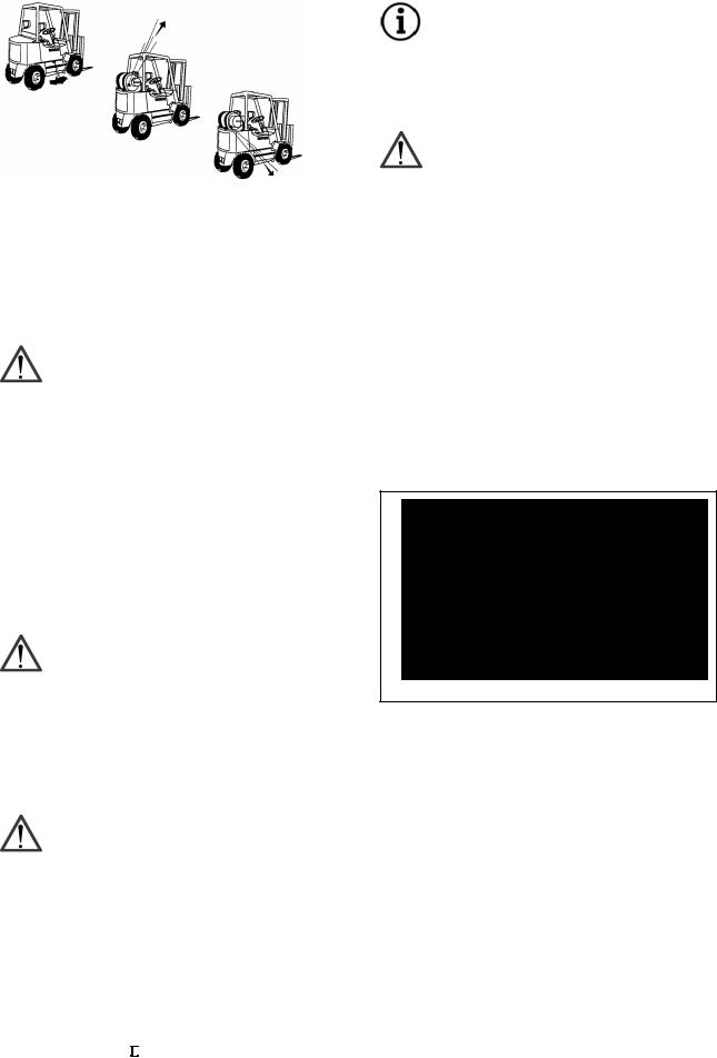
Propane has a heavier than air vapor density and will fall if a leak occurs, while natural gas, by comparison, will rise in the event of a leak (Figure 1).
This is an important property that technicians need to be aware of when performing maintenance. When repairing propane machinery, the work should be performed in the lowest point of the facility where possible. The tank supply should be shut off, except when required for running equipment.
Diesel
CNG
Figure 1 |
LPG |
G420E/G424E Tier LP Engine |
7 |
Working with LPG Equipment |
CHAPTER 0 LPG AND LPG FUEL TANKS
LPG Fuel Supply
Liquefied petroleum gas (LPG) consists mainly of propane, propylene, butane, and butylenes in various mixtures. LPG is produced as a by-product of natural gas processing or it can be obtained from crude oil as part of the oil refining process. LPG, like gasoline, is a compound of hydrogen and carbon, commonly called hydrocarbons.
In its natural state, propane is colorless and odorless; an odorant (ethyl mercaptan) is added to the fuel so its presence can be detected. There are currently three grades of propane available in the United States. A propane grade designation of HD5 (not exceeding 5% propylene), is used for internal combustion engines while much higher levels of propylene (HD10) are used as commercial grade propane along with a commercial propane /butane mixture.
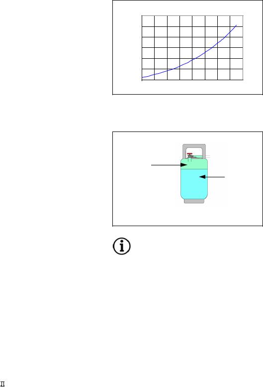
The same principle is applied to LPG in a container, commonly referred to as an LPG tank or cylinder. Typically an LPG tank is not filled over 80% capacity allowing for a 20% vapor expansion space. Outside air temperature effect’s an LPG tank and must be considered when using an LPG system. (Figure 2) shows the relationship between pressure and temperature in a LPG tank at a steady state condition.
LPG Tank Pressure VS Temperature
|
300 |
|
|
|
|
|
|
|
|
|
250 |
|
|
|
|
|
|
|
|
psig |
200 |
|
|
|
|
|
|
|
|
|
|
|
|
|
|
|
|
|
|
Pressure, |
150 |
|
|
|
|
|
|
|
|
100 |
|
|
|
|
|
|
|
|
|
|
50 |
|
|
|
|
|
|
|
|
|
0 |
|
|
|
|
|
|
|
|
|
-20 |
0 |
20 |
40 |
60 |
80 |
100 |
120 |
140 |
Figure 2 |
|
|
Temperature, deg F |
|
|
|
|||
APPROXIMATE COMPOSITION OF HD5 PROPANE BY VOLUME
Propane |
Propy |
Butane |
Iso- |
Methane |
TOTAL |
|
(C3H8) |
lene |
(C4H10) |
Butane |
(CH4) |
||
|
||||||
|
|
|
|
|
|
|
90.0% |
5%max. |
2.0% |
1.5% |
1.5% |
100% |
|
min. |
||||||
|
|
|
|
|
An advantage of LPG is the ability to safely store and transport the product in the liquid state. In the liquid state propane is approximately 270 times as dense as it is in a gaseous form. By pressurizing a container of LPG we can effectively raise the boiling point above –44 deg. C / -42 deg. C, keeping the propane in liquid form. The point at which the liquid becomes a gas (boiling point) depends on the amount of pressure applied to the container.
This process operates similarly to an engine coolant system where water is kept from boiling by pressurizing the system and adding a mixture of glycol. For example water at normal atmospheric pressure will boil at 212 deg. F / 100 deg. C. If an engines operating temperature is approximately 230 deg. F / 110 deg. C, then the water in an open unpressurized cooling system would simply boil off into steam, eventually leaving the cooling system empty and over heating the engine. If we install a 10 PSIG cap on the radiator, pressurizing the cooling system to 10 PSIG, the boiling point of the water increases to 242 deg. F / 117 deg. C, which will cause the water to remain in liquid state at the engines operating temperature.
With 128 PSIG vapor pressure acting against the liquid propane the boiling point has been raised to slightly more than 80 deg. F / 27 deg. C.
Compressed |
|
Vapor |
|
128 PSIG |
Liquid |
|
Propane |
LPG Tank
Figure 3
NOTE
Vapor pressure inside an LPG tank depends on the ambient air temperature outside the tank, not the amount of liquid inside the tank. A tank that is ¾ full of liquid propane at 80 deg. F will contain the same vapor pressure as a tank that is only ¼ full of liquid propane.
LPG’s relative ease of vaporization makes it an excellent fuel for low-rpm engines on start-and-stop operations. The more readily a fuel vaporizes the more complete combustion will be.
Because propane has a low boiling point (-44F), and is a low carbon fuel, engine life can be extended due to less cylinder wall wash down and little, if any, carbon build up.
G420E/G424E Tier LP Engine |
8 |
LPG and LPG Fuel Tanks |
LPG Fuel Tanks
The two styles of LPG storage containers available for industrial use and lift truck applications are portable universal cylinders and permanently mounted tanks. Portable universal cylinders are used primarily for off-highway vehicles and are constructed in accordance with the DOT-TC (United States Department of Transport – Transport Canada). The cylinders are referred to as universal because they can be mounted in either a vertical or horizontal position (Figure 4).
Figure 4
NOTE
A 375-psig, relief valve is used on a DOT forklift tank. The relief valve must be replaced with a new valve after the first 12 years and every 10 years thereafter.
The tank must be discarded if the collar is damaged to the point that it can no longer protect the valves. It must also be replaced if the foot ring is bent to the point where the tank will not stand or is easily knocked over.
Installing LPG Fuel Tanks
When installing a tank on a lift truck, the tank must be within the outline of the vehicle to prevent damage to the valves when maneuvering in tight spaces.
Horizontal tanks must be installed on the saddle that contains an alignment pin, which matches the hole in the collar of the tank. When the pin is in the hole, the liquid withdrawal tube is positioned to the bottom of the tank. A common problem is that often these guide-pins are broken off, allowing the tank to be mounted in any position. This creates two problems. 1). When the liquid withdrawal tube is exposed to the vapor space, it may give a false indication that the tank is empty, when it actually is not. 2). The safety relief valve may be immersed in liquid fuel. If for any reason the valve has to vent, venting liquid can cause a serious safety problem,
CAUTION
When empty, the tank is exchanged with a pre-filled replacement tank. When exchanging a tank, safety glasses and gloves should be worn.
G420E/G424E Tier LP Engine |
9 |
LPG and LPG Fuel Tanks |
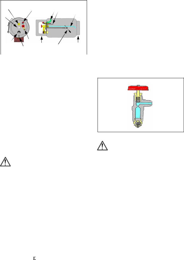
LPG Fuel Tank Components |
Service Valve |
2 |
3 |
7 |
8 |
9 |
|
|
|
|
1
|
6 |
4 |
|
10 |
|
12 |
11 |
||
Figure 5 |
5 |
|
|
|
|
|
|
||
|
|
|
|
|
(1) |
Fuel Gauge |
(2) 80% Stop Bleeder |
|
|
(3) |
Pressure Relief Valve |
|
|
|
(4) |
Service Valve (Tank end male coupling) |
(5) Filler Valve |
||
(6)Alignment Pin
(7)Vapor Withdrawal Tube (Only used with Vapor Withdrawal)
(8) 80% Limiter Tube (9) Liquid Withdrawal Tube
(10) Foot Ring (11) Fuel Level Float (12) Collar
Fuel Gauge
In figure 5 a visual fuel gauge is used to show the fuel level in the tank. A mechanical float mechanism detects the liquid propane level. A magnet on the end of the float shaft moves a magnetic pointer in the fuel gauge. Some units have an electronic sending unit using a variable resistor, installed in place of a gauge for remote monitoring of the fuel level. The gauge may be changed with fuel in the tank. DO NOT
REMOVE THE FOUR LARGE FLANGE BOLTS THAT RETAIN THE FLOAT ASSEMBLY, WITH FUEL IN THE TANK!
WARNING
It is not a legal practice to fill the tank through the liquid contents gauge.
In some applications a fixed tube fuel indicator is used in place of a float mechanism. A fixed tube indicator does not use a gauge and only indicates when the LPG tank is 80% full. The fixed tube indicator is simply a normally closed valve that is opened during refueling by the fueling attendant. When opened during refueling and the tanks LPG level is below 80%, a small amount of vapor will exit the valve. When the LPG tank level reaches 80% liquid propane will begin exiting the valve in the form of a white mist (Always wear the appropriate protective apparel when refueling LPG cylinders). In order for this type of gauge to be accurate, the tank must be positioned properly. When full (80% LPG) the valve is closed by turning the knurled knob clockwise. Typically a warning label surrounds the fixed tube gauge which reads STOP FILLING WHEN
LIQUID APPEARS.
The service valve is a manually operated valve using a small hand wheel to open and close the fuel supply to the service line (fuel supply line). The service valve installs directly into the tank and has two main categories, liquid and vapor service valves. Liquid service valves used on portable LPG tanks use a 3/8” (3/8” NPT) male pipe thread on the service valve outlet for attachment of a quick disconnect coupler.
An excess flow valve is built into the inlet side of the service valve as a safety device in case of an accidental opening of the service line or damage to the service valve itself. The excess flow valve shuts off the flow of liquid propane if the flow rate of the liquid propane exceeds the maximum flow rate specified by the manufacturer.
 Outlet
Excess Flow
 Valve
Valve
Figure 6
CAUTION
When the tank is in use the service valve should be completely open. If the valve is partly open, the vehicle may not be getting enough fuel to operate efficiently.
In addition to possibly starving the engine for fuel, a partly open valve may restrict the flow enough to prevent the excess flow valve from closing in the event of a ruptured fuel line.
Most liquid service valves have an internal hydrostatic relief valve and are usually labeled “LIQUID WITH INTERNAL RELIEF”. The hydrostatic relief valve protects the fuel service line between the tank and the lock off from over pressurization. The internal hydrostatic relief valve has a minimum opening pressure of 375 PSIG and a maximum pressure of 500 PSIG. These type of relief valves have an advantage over external relief valves because the propane is returned to the tank in the event of an over pressurization instead of venting the propane to atmosphere.
G420E/G424E Tier LP Engine |
10 |
LPG and LPG Fuel Tanks |
Quick Disconnect Coupling
The liquid withdrawal or service valve on a DOT tank has male threads and accepts the female portion of a quick disconnect coupling (Figure 8). The female portion is adapted to the liquid hose going to the fuel system. Both halves are equipped with 100% shutoffs, which open when coupled together to allow fuel flow. The coupler has two seals. One is an o-ring and the other is a flat washer. The o-ring prevents leakage from the shaft on the other coupling and the flat washer seals when the coupler is fully connected.
NOTE
The flat seal and/or the o-ring will sometimes pop off when disconnecting and slide up the shaft of the mating connector, causing the valve not to open when fully mated. The extra washer or o- ring must be removed from the shaft and the coupling reconnected.
Figure 8
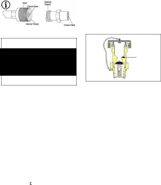
Filler Valve
The liquid filler valve (Figure 9) has a male thread to receive a fuel nozzle and typically has a plastic or brass screw on cap that is retained with a small chain or plastic band to keep debris out of the filler valve. The filler valve is a one-way flow device that uses two check valves to allow fuel to enter the tank but prevent it from exiting. Both check valves are backpressure type check valves, designed so that backpressure from the tank assists the check valves own spring pressure to close the valve. The first valve uses a neoprene on metal seal and the second valve uses a metal on metal seal.
A weakness ring is machined into the filler valve just above the check valves and will allow the filler valve to shear off in case of an accident. The valve will break or shear off above the check valves so that the tank will be sealed and no liquid propane can escape.
Weakness
Ring
Figure 9
G420E/G424E Tier LP Engine |
11 |
MI-04 System Overview |
CHAPTER 1 ENGINE SPECIFICATION
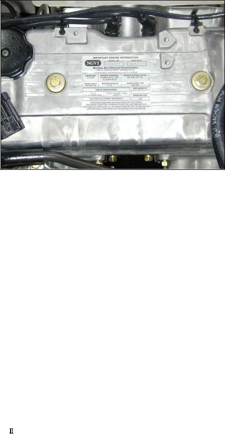
Indication of Engine Serial Number
G420E/G424E Tier LP Engine |
12 |
Engine Specification |

Specifications(G420E)
GENERAL DESCRIPTION
ENGINE TYPE: |
Water-cooled, Inline 4-Cycle, 4-Cylinders |
|
|
COMBUSTION SYSTEM: |
Naturally Aspirated 1-Venturi Intake Manifold |
|
|
Semi-spherical Combustion chamber |
|
||
|
|
||
EXHAUST SYSTEM: |
Cast Iron, Dry |
|
|
VALVE CONFIGURATION: |
OHC, 2 Valves per Cylinder |
|
|
DISPLACEMENT: |
1,997 cc (122 CID) |
|
|
BORE: |
85 mm (3.35 in.) |
|
|
STROKE: |
88 mm (3.46 in.) |
|
|
COMPRESSION RATIO: |
8.5:1 |
|
|
COMPRESSION PRESSURE: |
1,128 kPa (163.5 psi) |
|
|
VALVE TIMING: |
Intake Valve: 12° BTDC(Open)/ 40° ABDC(Close) |
||
Exhaust Valve: 54° BBDC(Open)/ 6° ATDC(Close) |
|||
|
|||
FIRING ORDER: |
1-3-4-2 |
|
|
SPARK PLUGS: |
BPR5ES: 0.7-0.8 mm (0.028-0.031 in.) Air Gap |
|
|
WEIGHT: |
139 Kg (306 lbs.), Dry |
|
|
ROTATION: |
Counter-Clockwise (CCW) when viewed from Flywheel End |
||
FUELTYPE: |
LPG |
|
|
GOVERNED SPEED: |
2400 +/- 25 RPM |
|
|
IDLE RPM: |
700 +/- 25 RPM |
|
|
IGNITIOIN TIMING: |
Electronic controlled by ECM |
|
|
LP FUEL SYSTEM |
|
|
|
MIXER: |
Piston Type Air Valve Assembly inside, Downdraft |
||
REGULATOR: |
Two-Stage Negative Pressure Regulator |
|
|
FUEL FILTRATION: |
40 Microns Maximum |
|
|
COOLING SYSTEM |
|
|
|
WATER PUMP ROTATION: |
V-Belt Drive - Clockwise (CW) when viewed from engine front |
||
THERMOSTAT: |
Opening Temperature: 82°C (180°F) |
|
|
Fully Open Temperature: 95°C (203°F) |
|
||
|
|
||
COOLING WATER CAPACITY |
3.1 L (block only) |
|
|
LUBRICATION SYSTEM |
|
|
|
OIL PRESSURE: |
450 kPa (65 psi) @ Hi Idle |
|
|
50 kPa (7 psi) @ Low Idle |
|
||
|
|
||
OIL TEMPERATURE: |
Upper Limit: 125°C (257°F) |
|
|
Recommended: 99 - 110°C (210 - 230°F) |
|
||
|
Lower Limit: 80°C (176°F) |
|
|
CRANKCASE CAPACITY: |
3.7 L |
|
|
OIL FILTER: |
0.3 L |
|
|
ENGINE OIL SPECIFICATION: |
API - SJ, SAE 10W30 or SAE 5W30 |
|
|
ENGINE ELECTRICAL |
|
|
|
IGNITION TYPE: |
Electronic Advanced by ECM |
|
|
IGNITION COIL: |
12 V operation volt, Ignition driver circuitry inside |
||
DISTRIBUTOR: |
Mitsubishi Distributor |
|
|
STARTER MOTOR: |
12 Volt, 1.2 kW, Reduction drive |
|
|
ALTERNATOR: |
12 Volt, 61 Amp |
|
|
ENGINE OIL PR. S/W: |
24.5 kPa (3.6 psi) |
|
|
ENGINE CONTROL MODULE(ECM): |
12 V operation volt, 24 pins of I/O |
|
|
VR SENSOR: |
Magnetic pick up sensor |
|
|
TMAP: |
Intake Air Temp. & Manifold Absolute Press. Sensor |
||
PEDAL ANGLE SENSOR: |
Two-Output Signals (Installed on Accelerator Pedal) |
||
OXYGEN SENSOR: |
Heated Exhaust Gas Oxygen Sensor (HEGO) |
|
|
12 V operation volt |
|
||
|
|
||
ECT-ECM: |
Engine Coolant Temperature Sensor for ECM |
|
|
ECT-GAUGE |
Engine Coolant Temp. Sensor for GAUGE on Instrument Panel |
||
TPS: |
Throttle Position Sensor (built in Throttle Body) |
|
|
THROTTLE BODY: |
Electronic Throttle Body |
|
|
FUEL TRIM VALVE (FTV): |
12 V operation volt |
|
|
LP FUEL LOCK-OFF: |
12 V operation volt, ON/OFF Control by ECM |
|
|
EXHAUST SYSTEM |
|
|
|
CATALYTIC MUFFLER: |
Three-way Catalyst included |
|
|
|
|
|
|
G420E/G424E Tier LP Engine |
13 |
Engine Specification |
|

Specifications(G424E)
GENERAL DESCRIPTION
ENGINE TYPE: |
Water-cooled, Inline 4-Cycle, 4-Cylinders |
||
COMBUSTION SYSTEM: |
Naturally Aspirated 1-Venturi Intake Manifold |
||
Semi-spherical Combustion chamber |
|||
|
|||
EXHAUST SYSTEM: |
Cast Iron, Dry |
|
|
VALVE CONFIGURATION: |
OHC, 2 Valves per Cylinder |
||
DISPLACEMENT: |
2,350 cc (143 CID) |
|
|
BORE: |
86.5 mm (3.41 in.) |
|
|
STROKE: |
100 mm (3.94 in.) |
|
|
COMPRESSION RATIO: |
8.6:1 |
|
|
COMPRESSION PRESSURE: |
1,128 kPa (163.5 psi) |
|
|
VALVE TIMING: |
Intake Valve: 12° BTDC(Open)/ 40° ABDC(Close) |
||
Exhaust Valve: 54° BBDC(Open)/ 6° ATDC(Close) |
|||
|
|||
FIRING ORDER: |
1-3-4-2 |
|
|
SPARK PLUGS: |
BPR5ES: 0.7-0.8 mm (0.028-0.031 in.) Air Gap |
||
WEIGHT: |
146 Kg (322 lbs.), Dry |
|
|
ROTATION: |
Counter-Clockwise (CCW) when viewed from Flywheel End |
||
FUELTYPE: |
LPG |
|
|
GOVERNED SPEED: |
2600 +/- 25 RPM |
|
|
IDLE RPM: |
700 +/- 25 RPM |
|
|
IGNITIOIN TIMING: |
Electronic controlled by ECM |
||
LP FUEL SYSTEM |
|
|
|
MIXER: |
Piston Type Air Valve Assembly inside, Downdraft |
||
REGULATOR: |
Two-Stage Negative Pressure Regulator |
||
FUEL FILTRATION: |
40 Microns Maximum |
|
|
COOLING SYSTEM |
|
|
|
WATER PUMP ROTATION: |
V-Belt Drive - Clockwise (CW) when viewed from engine front |
||
THERMOSTAT: |
Opening Temperature: 82°C (180°F) |
||
Fully Open Temperature: 95°C (203°F) |
|||
|
|||
COOLING WATER CAPACITY: |
3.1 L (block only) |
|
|
LUBRICATION SYSTEM |
|
|
|
OIL PRESSURE: |
50 kPa (7 psi) @ Low Idle 450 kPa (65 psi) @ Hi Idle |
||
|
Upper Limit: |
125°C (257°F) |
|
OIL TEMPERATURE: |
Recommended: |
99 - 110°C (210 - 230°F) |
|
|
Lower Limit: |
80°C (176°F) |
|
CRANKCASE CAPACITY: |
3.7 L |
|
|
OIL FILTER: |
0.3 L |
|
|
ENGINE OIL SPECIFICATION: |
API - SJ, SAE 10W30 or SAE 5W30 |
||
ENGINE ELECTRICAL |
|
|
|
IGNITION TYPE: |
Electronic Advanced by ECM |
||
IGNITION COIL: |
12 V operation volt, Ignition driver circuitry inside |
||
DISTRIBUTOR: |
Mitsubishi Distributor |
|
|
STARTER MOTOR: |
12 Volt, 1.2 kW, Reduction drive |
||
ALTERNATOR: |
12 Volt, 61 Amp |
|
|
ENGINE OIL PR. S/W: |
24.5 kPa (3.6 psi) |
|
|
ENGINE CONTROL MODULE(ECM): |
12 V operation volt, 24 pins of I/O |
||
VR SENSOR: |
Magnetic pick up sensor |
||
TMAP: |
Intake Air Temp. & Manifold Absolute Press. Sensor |
||
PEDAL ANGLE SENSOR: |
Two-Output Signals (Installed on Accelerator Pedal) |
||
OXYGEN SENSOR: |
Heated Exhaust Gas Oxygen Sensor (HEGO) 12 V operation volt |
||
ECT-ECM: |
Engine Coolant Temperature Sensor for ECM |
||
ECT-GAUGE |
Engine Coolant Temp. Sensor for GAUGE on Instrument Panel |
||
TPS: |
Throttle Position Sensor (built in Throttle Body) |
||
THROTTLE BODY: |
Electronic Throttle Body |
||
FUEL TRIM VALVE (FTV): |
12 V operation volt |
|
|
LP FUEL LOCK-OFF: |
12 V operation volt, ON/OFF Control by ECM |
||
EXHAUST SYSTEM |
|
|
|
CATALYTIC MUFFLER: |
Three-way Catalyst included |
||
|
|
|
|
G420E/G424E Tier LP Engine |
14 |
Engine Specification |
|

CHAPTER 2 MI-04 LPG SYSTEM OPERATIONAL OVERVIEW
MI-04 General Description
MI-04 control system is designed to provide a complete, fully integrated solution that will meet or exceed TIER-2 Large Spark Ignited Engines emission standards established by the California Air Research Board (CARB) and the Environmental Protection Agency (EPA) for 2004. The MI-04 is a closed loop system utilizing a catalytic muffler to reduce the emission level in the exhaust gas. In order to obtain maximum effect from the catalyst, an accurate control of the air fuel ratio is required. A small engine control module (SECM) uses a heated exhaust gas oxygen sensor (HEGO) in the exhaust system to monitor exhaust gas content.
MI-04 System with the N-CA55-500 Mixer
Fault Light |
Fuel Filter |
|
|
|
|
|
|
Key switch |
|
LP Fuel Line |
|
|
Fuel Lock |
|
|
|
Main |
|
|
Accel Pedal |
|
|
|
PWR |
|
|
|
APP |
Relay |
Converter |
|
|
|
||
|
Vacuum Line |
|
|
Air Cleaner |
Coolant Line |
|
Fuel Trim Valve |
|
Mixer |
|
|
|
DBW Throttle |
TPS |
SECM |
Oxygen |
TMAP |
|
|
|
|
Catalytic |
Engine |
Distributor |
|
||
|
|
|
Muffler |
VR Sensor |
|
|
|
|
|
|
Coolant Temp Sensor |
Figure 10
G420E/G424E Tier LP Engine |
15 |
System Operational Overview |
The SECM makes any necessary corrections to the air fuel ratio by controlling the inlet fuel pressure to the air/fuel mixer by modulating the fuel trim valve (FTV) connected to the regulator. Reducing the fuel pressure leans the air/fuel mixture and increasing the fuel pressure enriches the air/fuel mixture. To calculate any necessary corrections to the air fuel ratio, the SECM uses a number of different sensors to gain information about the engines performance. Engine speed is monitored by the SECM through a variable reluctance (VR) sensor. Intake manifold air temperature and absolute pressure is monitored with a (TMAP) sensor. The MI-04 is a drive by wire (DBW) system connecting the accelerator pedal to the electronic throttle through the electrical harness, mechanical cables are not used. A throttle position sensor (TPS) monitors throttle position in relation to the accelerator pedal position sensor (APP) feedback. Even engine coolant temperature is monitored by the SECM. The SECM controller has full adaptive learning capabilities, allowing it to adapt control function as operating conditions change. Factors such as ambient temperature, fuel variations, ignition component wear, clogged air filter, and other operating variables are compensated.
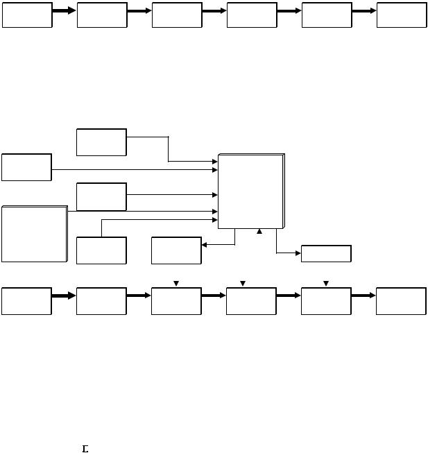
Open Loop LP Fuel System
Fuel |
LP |
LP |
Governor |
Engine |
Muffler |
Lock-Off |
Converter |
Mixer |
|
|
|
G420/G424 Open Loop LP Fuel System
MI-04 Closed Loop LP Fuel System
|
VR |
|
|
|
|
|
Sensor |
|
|
|
|
Coolant |
|
|
|
|
|
Sensor |
|
|
Small |
|
|
|
TMAP |
|
Engine |
|
|
|
|
Control |
|
|
|
|
Sensor |
|
Module |
|
|
Acceleration |
|
|
(SECM) |
|
|
pedal |
|
|
|
|
|
Angle |
Oxygen |
Fuel Trim |
|
|
|
Sensor |
|
Smart Coil |
|
||
Sensor |
Valve |
|
|
||
|
|
|
|||
Fuel |
LP |
LP |
Electronic |
Engine |
Catalytic |
Lock-Off |
Converter |
Mixer |
Throttle |
|
Muffler |
G420E/G424E Closed Loop LP Fuel System
G420E/G424E Tier LP Engine |
16 |
System Operational Overview |
MI-04 LP Fuel Filter |
MI-04 Fuel Lock-Off (Electric) |
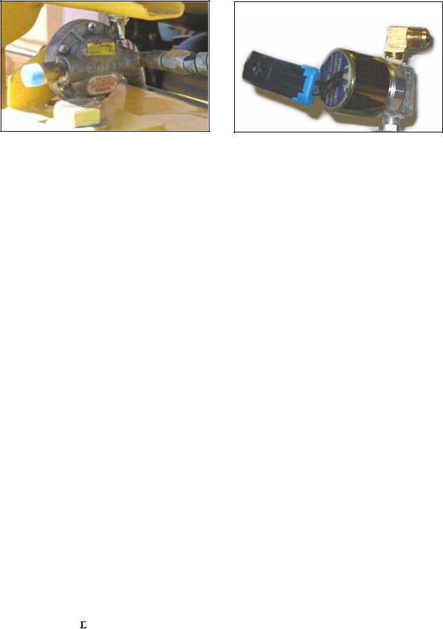
Figure 11
After exiting the fuel tank, liquid propane passes through a serviceable inline fuel filter to the electric fuel lock off. (Figure 11) shows a typical inline type LP fuel filter manufactured by Century. The primary function of the fuel filter is to remove particles and sediments that have found their way into the tank. The LP fuel filter will not remove heavy end solids and paraffin’s that build up in LPG fuel systems as a result of vaporization.
Figure 12
The fuel lock-off is a safety shutoff valve, normally held closed by spring pressure, which is operated by an electric solenoid and prevents fuel flow to the regulator/converter when the engine is not in operation. This is the first of three safety locks in the MI-04 system. (Figure 12) shows the electric fuel lock assembly.
In the MI-04 design, power is supplied to the fuel lock-off with the SECM controlling the lock-off ground (earth) connection. The lock-off remains in a normally closed (NC) position until the key switch is activated, this supplies power to the lock-off and the SECM but will not open the lock-off until the SECM provides the lock-off ground connection. This design gives the SECM full control of the lock-off while providing additional safety by closing the fuel lock-off in the unlikely event of a power failure, wiring failure or module failure.
When the liquid service valve in the fuel container is opened liquid propane flows through the LP filter and through the service line to the fuel lock-off. Liquid propane enters the lock-off through the ¼” NPT liquid inlet port and stops with the lock-off in the normally closed position. When the engine is cranked over the main power relay applies power to the lock-off and the SECM provides the lock-off ground causing current to flow through the windings of the solenoid creating a magnetic field. The strength of this magnetic field is sufficient to lift the lock-off valve off of its seat against spring pressure. When the valve is open liquid propane, at tank pressure, flows through the lock-off outlet to the pressure regulator/converter. A stall safety shutoff feature is built into the SECM to close the lock-off in case of a stall condition. The SECM monitors three engine states. Crank, when the VR sensor detects any engine revolutions. Stall, when the key is in the ON position but the VR sensor detects no engine revolutions, and the Run state, when the engine reaches pre-idle RPM. When an operator turns on the key switch the lock-off is opened but if the operator fails to crank the engine, the SECM will close the lock-off after 5 seconds.
G420E/G424E Tier LP Engine |
17 |
System Operational Overview |
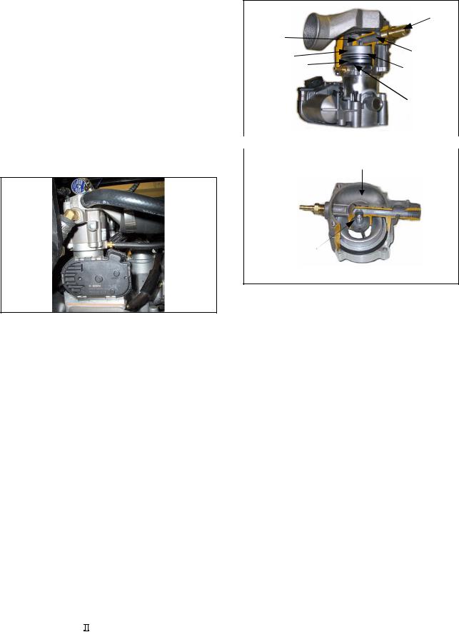
MI-04 N-2001
Regulator/Converter
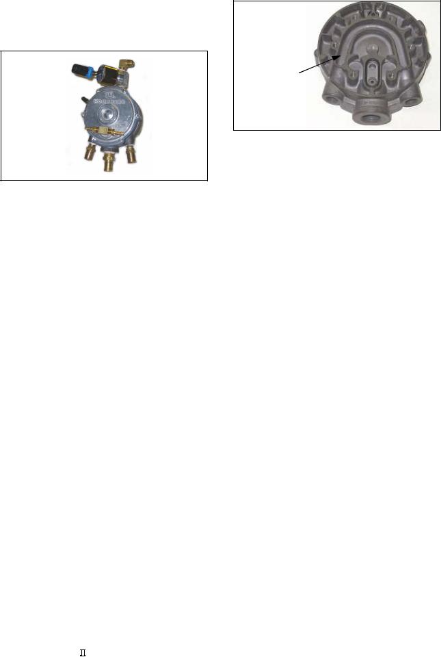
Figure 13
After passing through the electric fuel lock-off, liquid propane enters the N-2001 regulator/converter (Figure 13). The N-2001 functions as a fuel vaporizer, converting liquid propane to vapor propane and as a two-stage negative pressure regulator, supplying the correct vapor propane fuel pressure to the mixer.
The regulator is normally closed requiring a vacuum signal (negative pressure) to allow fuel to flow. This is the second of three safety locks in the MI-04 system. If the engine stops, vacuum signal stops and fuel flow will automatically stop when both the secondary (2nd stage) valve and the primary (1st stage) valve closes. Unlike most other regulator/converters, the N-2001 primary valve closes with fuel pressure rather than against pressure, extending primary seat life and adding additional safety.
Liquid propane must be converted into a gaseous form in order to be used as a fuel for the engine. When the regulator receives the desired vacuum signal it allows propane to flow to the mixer. As the propane flows through the regulator the pressure is reduced in two stages from tank pressure to slightly less than atmospheric pressure. As the pressure of the propane is reduced the liquid propane vaporizes and refrigeration occurs inside the regulator due to the large temperature drop inside the regulator from the vaporization of liquid propane. To replace heat lost to vaporization, engine coolant is supplied by the engine driven water pump and pumped through the regulator. Heat provided by this coolant is transferred through to the fuel vaporization chamber.
N-2001
Heat Transfer
Chamber
Coolant
Passage
Figure 14
(Figure 14) shows the heat chamber and the coolant passage in the N-2001.
G420E/G424E Tier LP Engine |
18 |
System Operational Overview |
N-2001 Theory of Operation
|
N-2001 |
|
Cutaway View |
7 |
8 |
6 |
5 |
9
4
1 |
3 |
|
2 |
||
|
Figure 15
Liquid propane, at tank pressure, enters the N-2001 through the fuel inlet port (1). Propane liquid then flows through the primary valve (2). The primary valve located at the inlet of the expansion chamber (3), is controlled by the primary diaphragm (4), which reacts to vapor pressure inside the expansion chamber. Two springs are used to apply force on the primary diaphragm in the primary diaphragm chamber (5), keeping the primary valve open when no fuel pressure is present.
A small port connects the expansion chamber to the primary diaphragm chamber. At the outlet of the expansion chamber is the secondary valve (6). The secondary valve is held close by the secondary spring on the secondary valve lever (7). The secondary diaphragm controls the secondary lever. When the pressure in the expansion chamber reaches 1.5 psi it causes a pressure/force imbalance across the primary diaphragm (8). This force is greater than the primary diaphragm spring pressure and will cause the diaphragm to close the primary valve.
Since the fuel pressure has been reduced from tank pressure to 1.5 psi the liquid propane vaporizes. As the propane vaporizes it takes on heat from the expansion chamber. This heat is replaced by engine coolant, which is pumped through the coolant passage of the regulator. At this point vapor propane will not flow past the expansion chamber of the regulator until the secondary valve is opened. To open the secondary valve a negative pressure signal must be received from the air/fuel mixer. When the engine is cranking or running a negative pressure
signal (vacuum) travels through the vapor fuel outlet connection of the regulator (9), which is the regulator secondary chamber, and the vapor fuel inlet of the mixer. The negative pressure in the secondary chamber causes a pressure/force imbalance on the secondary diaphragm, which overcomes the secondary spring force, opening the secondary valve and allowing vapor propane to flow out of the expansion chamber, through the secondary chamber to the mixer.
Because vapor propane has now left the expansion chamber, the pressure in the chamber will drop, causing the primary diaphragm spring force to reopen the primary valve allowing liquid propane to enter the regulator, and the entire process starts again. This creates a balanced condition between the primary and secondary chambers allowing for a constant flow of fuel to the mixer as long as the demand from the engine is present. The fuel flow is maintained at a constant output pressure, due to the calibrated secondary spring. The amount of fuel flowing will vary depending on how far the secondary valve opens in response to the negative pressure signal generated by the air/fuel mixer. The strength of that negative pressure signal developed by the mixer is directly related to the amount of air flowing through the mixer into the engine. With this process, the larger the quantity of air flowing into the engine, the larger the amount of fuel flowing to the mixer.
G420E/G424E Tier LP Engine |
19 |
System Operational Overview |
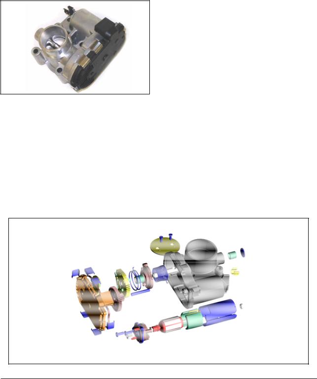
MI-04 N-CA55-500TR Mixer
Vapor propane fuel is supplied to the N-CA55-500TR mixer by the N-2001 pressure regulator/converter. The N-CA55-500TR mixer uses a piston type air valve assembly to operate a gas-metering valve inside the mixer. The gas-metering valve is normally closed, requiring a negative pressure (vacuum) signal from a cranking or running engine to open. This is the third of the three safety locks in the MI-04 system. If the engine stops or is turned off, the air valve assembly closes the gas-metering valve, stopping fuel flow past the mixer. The gas-metering valve controls the amount of fuel to be mixed with the incoming air at the proper ratio. The air/fuel mixture then travels past the throttle, through the intake manifold and into the engine cylinders where it is compressed, ignited and burned.
Figure 16
(Figure 16) shows the N-CA55-500TR mixer installed with the electronic throttle.
N-CA55-500-TR Air/Fuel Mixer
Theory of Operation
1
4 |
|
2 |
||
3 |
6 |
|||
5 |
||||
|
|
|||
|
|
7 |
||
Figure 17 |
|
|
|
|
|
|
|
||
|
|
|
||
View of Venturi Air |
|
|
||
Valve Piston |
|
Air Intake |
||
|
||||
Gas-Metering
Valve open
Figure 18
The air/fuel mixer is mounted in the intake air stream between the air cleaner and the throttle. The design of the main body incorporates a cylindrical bore or mixer bore, fuel inlet (1) and a gas discharge jet (2). In the center of the main body is the air valve assembly, which is made up of the piston air valve (3), the gas-metering valve (4), and air valve sealing ring (5), air valve spring (6) and the check valve plate (7). The gas-metering valve is permanently mounted to the piston air valve with a face seal mounted between the two parts.
When the engine is not running this face seal creates a seal against the gas discharge jet, preventing fuel flow with the aid (upward force) of the air valve spring. The outer surface of the piston air valve forms the venturi section of the mixer while the inner portion of the piston is hollow and forms the air valve vacuum chamber. The check valve plate seals off the bottom of the air valve vacuum (AVV) chamber and the air valve sealing ring seals the top portion of the AVV chamber as the piston moves against the air valve spring.
G420E/G424E Tier LP Engine |
20 |
System Operational Overview |
When the engine is cranked over it begins to draw in air, creating a negative pressure signal. This negative pressure signal is transmitted through a port in the check valve plate to the AVV chamber. A pressure/force imbalance begins to build across the air valve piston between the AVV chamber (below the piston) and atmospheric pressure above the piston. Approximately 6” W.C. (Water Column) of negative pressure is required to overcome the air valve spring force and push the air valve assembly (piston) downward off the valve seat. Approximately 24” W.C. pushes the valve assembly to the bottom of its travel in the full open position.
The amount of negative pressure generated is a direct result of throttle position and the amount of air flowing through the mixer to the engine. At low engine speeds, low AVV causes the piston air valve to move downward a small amount, creating a small venturi. At high engine speeds, high AVV causes the air valve piston to move much farther creating a large venturi. The variable venturi air/fuel mixer constantly matches venturi size to engine demand. To prevent engine reversion pulses, commonly encountered in small displacement engines, from having an effect on the piston AVV chamber, a check valve is incorporated on the check valve plate control port to the AVV chamber. The check valve is held open with gravity and remains open with any negative pressure signal from the engine. If a reverse pressure pulse, caused by engine reversion, travels up the intake manifold toward the mixer it will close the check valve for the duration of the pulse, preventing the pulse from entering the AVV chamber.
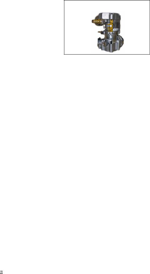
N-CA55-500TR
Air
Intake
Idle Mixture
 Adjustment
Screw
Electronic
Throttle
Figure 19
A main mixture adjustment valve on the fuel inlet of the N-CA55-500TR is not used in the MI-04 system, however an idle mixture adjustment is incorporated into the mixer (Figure 19).The idle mixture adjustment is an air bypass port, adjusting the screw all the way in, blocks off the port and enriches the idle mixture. Backing out the idle adjustment screw opens the port and leans the idle mixture. The idle mixture screw is a nylon type screw that is factory set with a tamper resistant cap installed after adjustment. Accurate adjustment of the idle mixture can only be accomplished by adjusting for a specific fuel trim valve (FTV) duty cycle with the service tool software, and should be only be adjusted by trained service technicians.
G420E/G424E Tier LP Engine |
21 |
System Operational Overview |
MI-04 Electronic Throttle
Conventional throttle systems rely on mechanical linkage to control the throttle valve. To meet fluctuating engine demands a conventional system will typically include throttle valve actuators designed to readjust the throttle valve opening in response to engine demand, together with idle control actuators or idle air bypass valves.
Figure 20
In contrast, the MI-04 system uses electronic throttle control (ETC). The SECM controls the throttle valve based on engine RPM, engine load, and information received from the Acceleration Pedal. Two mutually opposed potentiometers on the Acceleration Pedal assembly monitor accelerator pedal travel. The electronic throttle used in the MI-04 system is a Bosch 32mm Electronic Throttle Body DV-E5 (Figure 20). The DV-E5 is a single unit assembly, which includes the throttle valve, throttle-valve actuator (DC motor) and the throttle position sensor (TPS) (Figure 21).
The SECM calculates the correct throttle valve opening that corresponds to the driver’s demand, makes any adjustments needed for adaptation to the engine’s current operating conditions and then generates a corresponding electrical (driver) signal to the throttle-valve actuator.
There are multiple limp-home modes available with ETC. 1. If the throttle itself is suspected of being inoperable, the SECM will remove the power to the throttle motor. When the power is removed, the throttle blade returns to its “default” position, approximately 7% open. 2. If the SECM can still control the throttle but some other part of the system is suspected of failure, the SECM will enter a “Reduced Power” mode. In this mode, the power output of the engine is limited by reducing the maximum throttle position allowed. 3. In some cases, the SECM will shut the engine down. This is accomplished by stopping ignition, turning off the fuel, and disabling the throttle.
In place of a dual TPS design (TPS1 and TPS2), the SECM calculates correct throttle position (Predicted TPS) based on RPM and MAP and compares this to the actual throttle position, based on TPS1. The SECM continuously checks and monitors all sensors and calculations that effect throttle valve position whenever the engine is running. If any malfunctions are encountered, the SECM’s initial response is to revert to redundant sensors and calculated data. If no redundant signal is available or calculated data cannot solve the malfunction, the SECM will drive the system into one of it’s limp-home modes or shut the engine down, storing the appropriate fault information in the SECM.
Throttle Plate
Gear Drive
DC Drive Motor
Bosch 32mm Electronic Throttle Body DV-E5
Figure 21 Picture courtesy of Robert Bosch GmbH
G420E/G424E Tier  LP Engine 22 System Operational Overview
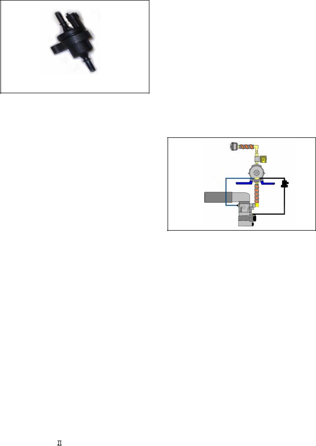
MI-04 Fuel Trim Valve
Fuel Trim Valve
The Fuel Trim Valve (FTV) is a two-way electric solenoid valve and is controlled by a pulse width modulated (PWM) signal provided by the SECM. The FTV is used to bias the output fuel pressure on the LPG regulator/converter (N-2001), by metering air valve vacuum (AVV) into the atmospheric side of the N-2001 secondary regulator diaphragm. An orifice balance line connected to the air inlet side of the mixer provides atmospheric reference to the N-2001 when the FTV is closed. The SECM uses feedback voltage from the O2 sensor to determine the amount of bias needed to the regulator/converter.
In normal operation the N2001 maintains fuel flow at a constant output pressure, due to the calibrated secondary spring. The amount of fuel flowing from the N2001 will vary depending on how far the secondary diaphragm opens the secondary valve in response to the negative pressure signal generated by the air/fuel mixer. One side of the N2001 secondary diaphragm is referenced to atmospheric pressure while the other side of the diaphragm reacts to the negative pressure signal from the mixer. If the pressure on the atmospheric side of the N2001 secondary diaphragm is reduced, the diaphragm will close the secondary valve until a balance condition exists across the diaphragm, reducing fuel flow and leaning the air/fuel mixture.
A branch-tee fitting is installed in the atmospheric vent port of the N2001 with one side of the branch-tee connected to the intake side of the mixer forming the balance line and referencing atmospheric pressure. The other side of the branch-tee fitting connects to the FTV inlet (small housing side). The FTV outlet (large housing connector side) connects to the AVV port. When the FTV is open AVV is sent to the atmospheric side of the N2001 secondary diaphragm, which lowers the reference pressure, closing the N2001 secondary valve and leaning the air/fuel mixture. The MI-04 system is calibrated to run rich without the FTV. By modulating (pulsing) the FTV the SECM can control the amount of AVV applied to the N2001 secondary diaphragm. Increasing the amount of times the FTV opens (modulation or duty cycle) causes the air/fuel mixture to become leaner; decreasing the modulation (duty cycle) enriches the mixture.
Balance Line
FTV
Figure 22
(Figure 22) shows the Fuel Trim Valve connected in the MI-04 system.
G420E/G424E Tier LP Engine |
23 |
System Operational Overview |
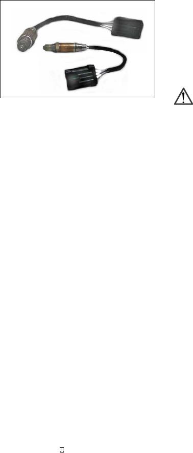
Heated Exhaust Gas Oxygen
Sensor (HEGO)
Figure 24
The HEGO sensor (Figure 24) installed in the exhaust manifold before the catalytic muffler is a basic zirconium type oxygen sensor comprised of a hollow cone-shaped internal element made of zirconium dioxide (ZrO2, a ceramic material), which is coated with a thin layer of micro-porous platinum. The outer layer is exposed to the exhaust stream, while the inner layer is vented to the atmosphere and attached to a wire that runs to the SECM. It operates like a galvanic cell with the zirconium dioxide acting as the electrolyte and the platinum layers serving as electrodes. Once the ZrO2 reaches approximately 600 deg. F., it becomes electrically conductive and attracts negatively charged ions of oxygen. These ions collect on the inner and outer platinum surfaces. Naturally, there's more oxygen in plain air than in exhaust, so the inner electrode will always collect more ions than the outer electrode, and this causes a voltage potential for electrons to flow. The concentration of oxygen in the exhaust stream determines the number of ions on the outer electrode, hence the amount of voltage produced. If the engine is running rich, little oxygen will be present in the exhaust, few ions will attach to the outer electrode, and voltage output will be relatively high. In a lean situation, more oxygen will be present, and that translates into more ions on the outer electrode, a smaller electrical potential, and less voltage. In order for the sensor to conduct and create an electrical signal below 600 deg. F., a heated element is added to the sensor housing. Two wires provide the necessary 12VDC and ground signal for the heater element. A fourth wire provides an independent ground for the sensor.
The HEGO stoichiometric air/fuel ratio voltage target is approximately 500mV and changes slightly as a function of speed and load. When the HEGO sensor sends a voltage signal less than 500mV the SECM interprets the air/fuel mixture to be lean. The SECM then decreases the duty cycle of the FTV lowering the amount of air valve vacuum (AVV) acting on the atmospheric side of the N2001 secondary diaphragm, increasing the regulator vapor propane output to richen the air/fuel mixture. The opposite is true if the SECM receives a voltage signal above 500mV from the HEGO. The air/fuel mixture would then be interpreted as being too rich and the SECM would increase the duty cycle of the FTV.
CAUTION
The HEGO sensor used is calibrated to work with the MI-04 system. Using alternate sensors may impact drivability and the ability of the system to diagnose rich and lean conditions.
G420E/G424E Tier LP Engine |
24 |
System Operational Overview |

MI-04 SECM
(General Description)
The Woodward Small Engine Control Module (SECM) controller has full authority over spark, fuel and air. Utilizing Motorola’s HCS12 micro controller, the SECM has 24 pins of I/O and is fully waterproof and shock hardened (Figure 23). To optimize engine performance and drivability, the SECM uses several sensors for closed loop feedback information.
These sensors are used by the SECM for closed loop control in three main categories:
zFuel Management
zLoad/Speed Management
zIgnition Management
SECM
Figure 23
The SECM monitors system parameters and stores any out of range conditions or malfunctions as faults in SECM memory. Engine run hours are also stored in memory. Stored fault codes can be displayed on the Malfunction Indicator Light (MIL) as flash codes or read by the MI-04 Service Tool software through a CAN (Controller Area Network) communication link.
Battery power (12 VDC) is supplied through the fuse block to the main power relay. The ignition key switch is used to energize the main power relay. A main power relay supplies 12 VDC power to the SECM, the heated element of the oxygen sensor, Fuel Lock-Off, Fuel Trim Valve (FTV) and the Smart Coil. The SECM supplies positive voltage to the electronic throttle actuator, oil pressure switch and the coolant temperature sensor. Transducer or sensor power (+5 VDC) is regulated by the SECM and supplied to the Temperature/Manifold Air Pressure Sensor (TMAP), Throttle Position Sensor (TPS), and the Accelerator Pedal Position Sensors (APP1 & APP2). The SECM provides a constant voltage (VCC) to the Smart Coil Driver, transducer ground for the all sensors, and a low side driver signal controlling the fuel lock-off, MIL and FTV.
MI-04 SECM
(Fuel Management)
During engine cranking at startup, the SECM provides a low side driver signal to the fuel lock-off, which opens the lock-off allowing liquid propane to flow to the N2001 regulator. A stall safety shutoff feature is built into the SECM to close the lock-off in case of a stall condition. The SECM monitors three engine states. Crank, when the VR sensor detects any engine revolutions. Stall, when the key is in the ON position but the VR sensor detects no engine revolutions, and the Run state, when the engine reaches pre-idle RPM. When an operator turns on the key switch the lock-off is opened but if the operator fails to crank the engine, the SECM will close the lock-off after 5 seconds.
To maintain proper exhaust emission levels, the SECM uses a heated exhaust gas oxygen sensor (HEGO) mounted before the catalyst, to measure exhaust gas content in the LP gas system. Engine speed is monitored by the SECM through a variable reluctance (VR) sensor. Intake manifold air temperature and absolute pressure is monitored with a (TMAP) sensor. The HEGO voltage is converted to an air fuel ratio value. This value is then compared to a target value in the SECM. The target value is based on optimizing catalyst efficiency for a given load and speed. The SECM then calculates any corrections that need to be made to the air fuel ratio.
The system operates in open loop fuel control until the engine has done a certain amount of work. This ensures that the engine and HEGO are sufficiently warmed up to stay in control. In open loop control, the FTV duty cycle is based on engine speed and load. Once the HEGO reaches operating temperature the fuel management is in closed loop control for all steady state conditions, from idle through full throttle. In closed loop mode, the FTV duty cycle is based on feedback from the HEGO sensor. In order to handle transient loads, engine RPM and load is compared to a threshold used by the SECM. When this threshold is exceeded, the FTV duty cycle will be set to a Feed Forward Adaptive value.
The SECM then makes any necessary corrections to the air fuel ratio by controlling the inlet fuel pressure to the air/fuel mixer Reducing the fuel pressure leans the air/fuel mixture and increasing the fuel pressure enriches the air/fuel mixture. Control is achieved by modulating the fuel trim
G420E/G424E Tier LP Engine |
25 |
System Operational Overview |
 Loading...