


DAEWOO DTQ-26S1FC, DTQ-26S1FS, DTQ-26S1FSP, DTQ-29S1FCN, DTQ-29S1FSN Service Manual
...Service Manual
Color Television
CHASSIS : CN-200I/A
NTSC-M SYSTEM
MODEL: DTQ-26S1FC/FS/FSP(CN-200I)
DTQ-29S1FCN/FSN/FSP(CN-200I)
DTQ-26S1HC/HS/HSP(CN-200A)
DTQ-29S1HC/HS/HSP(CN-200A)
DAEWOO ELECTRONICS CO., LTD. OVERSEAS SERVICE DEPT.


FEATURES
 FS (Frequency Synthesizer) Tuning System
 CATV Ready
 Monitor Look Design
 A/V IN. (Stereo)
 Stereo/Mono Function
ELECTRICAL SPECIFICATIONS
POWER INPUT |
|
|
FC |
SERIES |
AC 120V 60Hz |
FS |
SERIES |
AC 85V ~ AC 150V 60Hz |
FSP SERIES |
AC 220V 50Hz/60Hz |
|
POWER RATING |
|
|
26” MODELS |
100W |
|
29” MODELS |
105W |
|
INTERMEDIATE FREQUENCIES |
|
|
PICTURE IF CARRIER FREQUENCY |
45.75MHz |
|
SOUND IF CARRIER FREQUENCY |
41.25MHz |
|
COLOR SUB CARRIER FREQUENCY |
42.17MHz |
|
AUDIO OUTPUT RATING |
1.2W 2 |
|
SPEAKER |
2W 8 ohm 2 |
|
ANTENNA INPUT IMPEDANCE |
VHF/UHF 75 ohm UNBALANCED |
|
TUNING RANGES |
|
|
VHF |
|
2 THRU 13 |
UHF |
|
14 THRU 69 |
CATV |
1 THRU 125 |
|
CONTENTS
Safety Precautions |
3 |
Control View |
5 |
Important Service Notes |
7 |
Block Diagram |
8 |
General Adjustments |
10 |
Trouble Shooting Charts |
12 |
Description of Semiconductors |
20 |
Printed Boards |
21 |
Exploded View |
23 |
Schematic Diagram |
25 |
Parts List |
27 |
Option List |
36 |
2
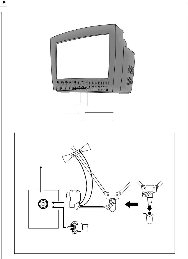

 CONTROL VIEW
F-CONNECTOR |
300 OHM-75 OHM |
COUPLING |
TRANSFORMER |
VHF |
75Ω |
FROM 75 OHM |
VHF ANTENNA WITH |
CABLE OR CABLE |
TV SYSTEM |
5 |
1. Overview of Your Equipment
Your TV comes with a remote control. The section below summarizes the buttons,controls, and terminals that you will use with your TV.
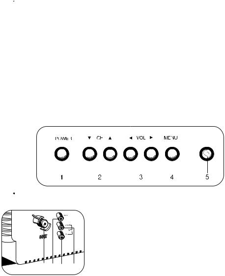
2.Your TV's Front Panel
1.POWER
Use this buttom to turn your TV on or off.
2. CH
CH
Use these buttom to change channels on your TV, or to select items in the menu system.
3.  VOL
VOL 
Use these buttom to change your TV s volume, to activate selections in the menu system, or to change audio and video settings.
4.MENU
Use this buttom to turn the TV s menu system on and off.
5.Remote control receiver
This receiver receives a signal from your remote control. Do not block it.
3. Your TV's Back Panel
|
|
|
|
1. |
Antenna terminal |
|
|
|
|
|
Use this terminal to attach an antenna or cable |
|
|
|
|
|
system to your TV. |
|
|
|
|
2. |
VIDEO IN |
|
|
|
|
|
This terminal allows the TV to receive a video |
|
|
|
|
|
signal from another components, such as a VCR. |
1 |
2 |
4 |
3 |
3. |
AUDIO R/MONO IN |
|
This terminal allows the TV to receive an audio |
||||
|
|
|
|
|
|
|
|
|
|
|
R/MONO signal from another components, such as |
|
|
|
|
a |
VCR. |
|
|
|
|
4. |
AUDIO L IN |
|
|
|
|
|
This terminal allows the TV to receive an audio L |
|
|
|
|
|
signal from another components, such as a VCR. |
6
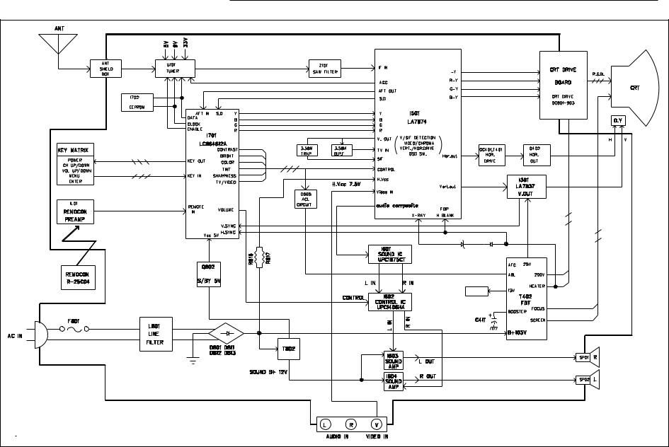
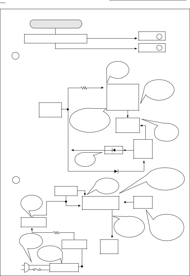
 BLOCK DIAGRAM (CN-200I)
8 |


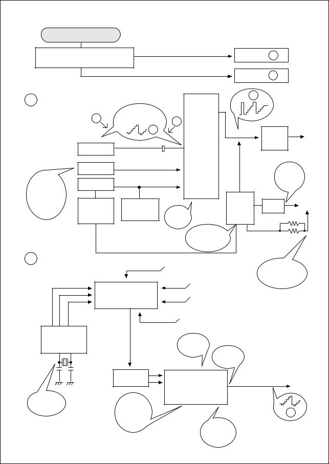
 BLOCK DIAGRAM (CN-200A)
9 |


 GENERAL ADJUSTMENTS
1. GENERAL
In the majority of cases, all color televisions will need only slight touch-up adjustment upon installation. Check the basic characteristics such as height, focus and subbasic characteristics such as height, focus and subbright. Observe the picture for good black and white details without objectionable color shading.
2. VERTICAL HEIGHT ADJUSTMENT
1)Tune in an active channel.
2)Adjust brightness and contrast controls for a good picture.
3)Adjust vertical height control (R305) for approximately one half inch over scan at top and bottom of picture screen.
4)Vertical centering adjustment R310 Horizontal centering adjustment R516.
3. FOCUS ADJUSTMENT
1)Tune in an active channel.
2)Adjust brightness, sharpness and contrast controls for a good picture.
3)Adjust focus control (part of T402) for sharp scanning lines and/or sharp picture.
4. RF AGC ADJUSTMENT
1)Tune in an active channel.
2)Using the attenuator, apply the signal of 60dBm to the antenna input terminal.
3)Turn RF AGC control (R113) full clockwise until snow or/and noise appears in the picture, then slowly turn control counter clockwise until snow or/and noise disappears.
5. HIGH VOLTAGE CHECK
High voltage is not adjustable but must be checked to verify that the receiver is operating within safe and efficient design limitations as specified:
1)Operate Receiver for at least 15 minutes at 120V AC line.
2)Set brightness sharpness, contrast and color control to minumum position (Zero beam).
3)Connect accurate high voltage meter to CRT anode. The reading should be 26kv~28kv
If a correct reading cannot be obtained, check circuity for malfunctioning components.
6. X-RADIATION PROTECTION CIRCUIT TEST
When service has been performed on the horizontal deflection system, high voltage system or B+system, the X- RADIATION protection circuit must be tested for proper operation as follows:
1)Operate receiver for at least 15 minutes at 120V AC line.
2)Adjust all customer controls for normal picture and sound.
3)Short R414(X-RAY Short test), and remove short clip.
4)If the operation of horizontal osc. does not stop in step The circuit must be repaired, before the set is returned to the customer.
7. CRT GRAY SCALE ADJUSTMENT
1)Tune in an active channel.
2)Set the COLOR control to minimum.
3)Turn the SCREEN control (on T402 fully counter-
clockwise.)
4)Rotate the RED, GREEN and BLUE BIAS controls (R917, R918, R919) counterclock wise from the maximum, set them to the position where notches in the knobs become parallel to the surface of P.C. Board.
5)Set the GREEN and BLUE DRIVE controls (R920, R921) to the mid position.
6)Turn the service switch SW901 (Service Position) on the CRT board.
7)Rotate the SCREEN control (on T402) gradually clockwise until the second horizontl line following the first line appears slightly on the screen. Then turn fully counterclockwise the two BIAS controls corresponding to the colors of the first and the second horizontal lines to eliminated the lines.
8)Set the SCREEN control to the position where the third horizontal line lights slightly on the screen.
9)Adjust the two BIAS control set to the minimum in item 7) above to obtain the slightly lighted horizontal line in the same levels of three (red, green, blue) colors. (The line should be white if the BIAS controls are adjusted properly.)
10)Turn the service switch SW901 again (Normal position on the CRT board.)
11)Press PICTURE-SEL, P-UP and set the brightness and contrast controls to the maximum.
12)Adjust the BLUE and GREEN DRIVE control to obtain proper white-blanced picture in high light areas.
13)Using P-SEL, P-DN key, set the brightness and contrast controls to obtain dark gray raster. Then check the white balance in low brightness. Of the white balance is not proper, retouch the BIAS controls and DRIVE controls to obtain a good white balance in both low and high light areas.
8. MAIN B+(103V) ADJUSTMENT
1)Tune in an active channel
2)Check TP10 (DC 103V Line) using D.V.M
3)Adjust voltage control (R809) for main B+(DC 103V)
9. SUB-BRIGHTNESS ADJUSTMENT
1)Tune in a color program.
2)Set the CONTRAST control to maximum and the BRIGHTNESS control to maximum and the SHARPNESS control to the center position.
3)Set the COLOR and TINT controls to center.
4)Set the SUB-BRIGHT control R522 to center and leave the receiver on five minutes in this state.
5)Watching the picture carefully, adjust the SUBBRIGHT control in the position where the picture does not show evidence of blooming in high brightness area and not appear too dark in low bright area.
6)Check for BRIGHTNESS controls at both extremes.
7)If the picture does not appear dark with the CONTRAST and BRIGHTNESS control turned to minimum, or not appear bright with the controls turned to maximum, adjust the SUB-BRIGHT control again for an acceptable picture.
10
10. PICTURE IF/AFT ADJUSTMENTS
NOTE : THIS RECEIVER IS TRANSISTORIZED AND SPECIAL CARE MUST BE TAKEN WHEN SERVICING. READ THE FOLLOWING (NOTES BEFORE ATTEMPTING ALIGNMENT)
 Alignment requires an exacting procedure and should be undertaken only when necessary.
 Isolation transformer must be used to prevent shock hazard.
 The test equipment specified or its equivalent is required to perform the alignment properly. Use of equipment which does not meet these requirements may result in improper alignment.
 Accurate equipment is essential to obtain proper alignment of this receiver.
 Use of excessive signal from a sweep generator can cause overloading of receiver circuit Overloading should be avoided to obtain a true response curve. Insertion of markers from the marker generator should not cause distortion of the response curve.
 The AC Power line voltage should be kept 120 volts while alignment is being performed.
  Do not attempt to disconnect any components while the receiver is in operation.
Make sure the power cord is disconnected before replacing any parts in the receiver.
TEST EQUIPMENT
Digital voltmeter 


 National Model VP-2600A or equivalent
Oscilloscope 


 Tektronix Model 2215A or equivalent.
Direct/Low-capacity probe 


 Tektronix Model P6120 or equivalent (Accessory of oscilloscope)
Color-Bar/Dot/Crosshatch generator 


 Tektronix Model 146 or equivalent.
PIF sweep marker generator 


 Nihon Tsushinki Model 4723 or equivalent
Power supply 


 Academy Model 150A or equivalent
Isolation transformer 


 Voltage adjustable type having capacity of at least 150 watts
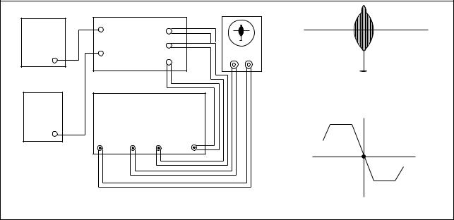
BLOCK DIAGRAM
B+ |
|
MAIN BOARD |
OSCILLOSCOPE |
|
|||
|
|
|
|
|
|
||
BIAS |
|
TP3 |
TP7 |
|
|
|
|
POWER |
|
|
|
|
|||
|
|
|
|
|
|
||
SUPPLY |
|
|
TP6 |
|
|
|
|
A |
|
TP5 |
|
Y |
|
||
|
|
X |
|
||||
(12V) |
|
|
|
||||
|
|
|
|
|
|
||
AGC |
|
|
|
|
|
45.75MHz |
|
|
|
|
|
Fig. 6 |
PIF Response |
||
BIAS |
PIF SWEEP/MARKER GEN. |
||||||
|
|
||||||
POWER |
|
|
|||||
|
|
|
|
|
|
||
SUPPLY |
|
|
|
|
|
|
|
B |
|
|
|
|
|
|
|
(4-5V) |
V |
H |
DETIN |
OUT |
|
|
|
|
|
|
|||||
|
|
|
|
|
|
P 45.75MHz |
|
|
Fig. 5 Picture IF Sweep Alignment |
Fig. 7 |
AFT Response Curve |
||||
1)Disconnect the  TUNER IF
 output from TP6 and connect equipment as shown above.
2)Set the sweep/marker generator for 30 Vrms.
3)Observe 1 Vp-p on scope by adjusting power supply B (4~5V).
4)Adjust PIF coil L505 for according beat signal with 45.75 MHz marker on scope (See Fig. 6).
5)Connect the  DET IN
 to TP7.
6)Adjust AFT coil L504 for center display at 45.75 MHz on scope (See Fig. 7).
7)After completing the above steps, disconnect equipment and adjust the AGC delay circuit as explained in the General Adjustments section of this manual.
11

 TROUBLE SHOOTING CHARTS
NO POWER |
|
|
|
|
|
|
DOES QC701(POWER ON/OFF TR) |
YES |
GO TO |
A |
|||
OPERATE? |
|
|
|
|
|
|
|
|
|
NO |
GO TO |
B |
|
|
|
|
|
|
||
A |
|
|
|
|
|
|
|
|
|
CHECK |
|
|
|
|
|
|
#30 |
|
|
|
|
|
|
(7.5V DC) |
|
|
|
|
|
R816 15K |
|
|
|
|
|
|
2WATT |
30 |
|
DOES |
|
|
|
|
|
SHUT DOWN |
||
|
|
|
|
|
||
|
|
|
|
|
CIRCUIT |
|
|
|
|
|
I501 |
OPERATE? |
|
|
|
|
|
|
|
|
CHECK TP10 |
103VDC |
|
|
24 |
|
|
26 |
|
|
|
|||
(MAIN B+ |
|
|
|
|
|
|
|
|
|
|
|
|
|
LINE) |
|
IF #26 NORMAL |
|
|
|
|
|
|
|
|
|
|
|
|
|
& NO OUTPUT AT |
|
|
|
|
|
|
#23 THEN |
|
Q402 |
|
|
|
|
CHANGE I501 |
|
H. OUTPUT |
CHECK |
|
|
|
|
|
|
|
Q402 |
|
|
|
|
|
|
COLLECTOR |
|
|
12V |
D406 |
12V |
T402 |
|
|
|
|
|
|||
|
|
|
|
|
F.B.T |
|
|
|
CHECK |
|
|
|
|
|
|
12V LINE |
|
|
|
|
|
|
|
D403 |
|
103V(B+) |
|
|
|
|
|
|
|
CHECK |
B |
|
|
|
|
|
ALL THE POINTS |
|
|
|
|
|
THEN CHANGE |
|
|
|
NORMAL: 5V |
|
|
I701 |
|
|
QC706 |
RESET: 0V |
|
|
|
|
|
RESET |
|
|
|
|
|
SHOULD |
|
16 I701 |
|
36 |
PWR |
|
BE |
|
|
42 |
CONTROL |
|
|
4.3V-5.2V |
|
12 LC864616A |
|
KEY |
|
|
5V |
|
|
|
|
|
|
Q802 |
|
|
|
OPEN LOAD |
KEY OPERATE? |
|
REGULATOR |
|
|
|
THEN CHECK |
||
|
|
|
CHECK DIODE |
|||
R808 |
|
|
|
#42 ON STATE |
||
|
|
|
D701 & SWITCH |
|||
|
|
|
|
4 ~5V |
|
|
|
|
|
|
|
KEY BOARD |
|
|
|
|
|
|
|
|
CHECK |
|
|
|
|
|
|
F801 |
T801 |
QC701 |
|
|
|
|
125V 5A |
|
|
|
|||
POWER |
|
|
|
|||
CHECK |
|
|
|
|
||
|
CONTROL |
|
|
|
||
LEAD |
|
|
|
|
||
|
|
|
|
|
|
|
SOLDERING |
|
|
|
|
|
|
L801 |
|
|
|
|
|
|
LINE FILTER |
|
|
|
|
|
|
|
|
12 |
|
|
|
|
NO PICTURE
OK
CHECK THE WAVE FORM OF
I501 #44 (2Vp-p)
NG
C
|
FC |
COMPOSITE |
|
|
21 |
|
|
|
|
||
|
VIDEO INPUT |
FS |
I501 |
||
|
|
||||
|
|
H |
|
LA 7674 |
|
|
QC201 |
|
C506 |
42 |
|
|
|
|
|
|
|
|
CONTRAST |
|
|
39 |
|
CHECK |
BRIGHT |
|
|
|
|
CONTROL |
|
|
31 |
|
|
|
|
|
|
||
(NORMAL) |
|
|
|
11 |
14 |
VOLTAGES |
|
|
|
||
|
|
|
|
|
|
#39: 5.0V |
D505 |
R522 |
|
|
|
#31: 3.9V |
CHECK |
|
|
||
ABL |
SUB-BRIGHT |
|
|
||
|
9V LINES |
|
|||
|
|
|
|
||
|
|
|
#11,14 |
|
|
|
|
|
|
CHECK |
|
|
|
|
|
ABL |
|
|
|
|
|
Ib = 1.2mA |
|
GO TO |
C |
GO TO |
D |
H |
|
Y-OUT |
QC501 |
||
VIDEO |
|||
|
|||
|
DRIVE |
||
|
|
CHECK |
|
|
|
210V |
|
H. BLANKING |
KINE |
||
|
|||
T402
FBT D404
R413
ABL H.T
R412
D
|
|
AGC |
|
|
|
CHECK |
|
|
|
|
|
|
HEATER |
ENA |
|
9V |
|
|
6.3Vrms |
|
|
|
|
|
|||
|
|
|
|
|
|
|
|
DATA |
U101 TUNER |
VT (33V) |
|
|
|
|
CLK |
|
|
|||
|
|
|
|
|
|
|
|
|
IF |
5V |
|
|
|
|
|
|
|
|
|
|
I701 |
|
|
|
|
|
|
LC864616A |
|
|
ADJUST |
|
||
10 |
11 |
|
|
RF-AGC |
|
|
|
|
R113 |
DETECTOR |
|
||
|
|
|
|
|
||
|
|
|
|
|
|
|
|
|
|
|
|
OUTPUT |
|
|
|
Z101 |
8 |
|
10 |
|
|
|
SAW FILTER |
9 |
I501 |
44 |
TO QC201 |
|
|
|
||||
|
|
|
|
|||
|
|
|
|
LA7674 |
|
|
CHECK |
|
CHECK |
|
2 |
11 14 |
|
CSB503E |
|
IF AGC |
|
|
|
H |
|
|
VTG. |
|
|
|
|
|
|
5VDC |
|
|
|
|
TP2 |
CHECK |
|
|
|
9V LINE |
|
#11, 14 |
13
NO SOUND(CN-200I) |
|
|
|
|
|
|
CHECK FOR SIGNAL |
|
|
|
|
GO TO |
E |
AT I501 #1 |
|
|
|
|
|
|
|
|
|
|
|
GO TO |
F |
E |
|
|
|
|
|
|
CHECK |
|
#1 |
|
|
|
|
MONO 100% MOD |
|
|
|
|
|
|
|
#2 9V(B+) |
|
|
|
|
|
-> 0.424 Vp-p |
|
|
|
|
|
|
|
|
I601 |
|
|
|
|
|
|
|
|
#19 |
CHECK 1Vp-p |
|
CHECK |
|
#12 |
|
#18 |
|
|
|
|
|
|
|||
EXT SOUND |
|
#13 |
(MUTE)#17 |
MUTE ON: 5V |
|
|
SIGNAL OFF:L |
|
|
||||
|
|
|
|
|
OFF: 0V |
|
|
|
#1 9V(B+) |
#4 |
CHECK 1Vp-p |
|
|
|
|
#2(0~5V) |
#6 |
|
||
|
|
|
|
|
||
|
|
I602 |
|
|
|
|
|
|
#8(0~5V) |
|
|
|
|
|
|
|
#7 |
CHECK 12VDC |
|
|
|
|
I604/I603 |
|
|
|
|
CHECK SOUND INPUT |
|
#3 |
#6 |
|
|
|
|
|
|
#5 |
CHECK SOUND OUTPUT |
|
|
F |
|
|
|
|
|
|
|
#11 |
|
#1 |
COMPOSITE SIGNAL |
|
|
CHECK 9V |
|
|
|
|
||
#14 |
|
|
|
I601 #1 |
|
|
|
|
|
|
|
|
|
|
#44 |
I501 |
|
|
|
|
|
LA7674 |
|
|
|
|
|
|
|
|
|
|
|
|
|
|
|
#4 |
|
CHECK FM DET |
|
|
|
|
|
|
CIRCUIT |
|
Z201 |
#48 |
|
|
|
|
|
|
|
|
|
|
|
|
CHECK SOUNDIF INPUT |
|
|
|
|||
|
|
14 |
|
|
|
|
 Loading...