


DTQ-14V1FS
Daewoo DTQ-14V1FS, DTQ-14V6FCB, DTQ-14V1FSP, DTQ-14V5FSP, DTQ-14V5FC User Manual 2
...
S/M No. : CN001A-020R1
✔ Caution:In this Service Manual, some parts can be changed for improving, their performance
without notice in the parts list.So,if you need the latest parts information, please refer
to PPL(Parts Price List) in Service information Center(http://svc.dwe.co.kr)
Service Manual
(Revision-1)
Color Television
CHASSIS : CN-001A
Model :
DTQ-14V1FC/20V1FC
DTQ-14V5FC/20V4FC
DTQ-14V1FS/20V1FS
DTQ-14V5FS/20V4FS
DTQ-14V3FS/20V3FS
DTQ-14U1FS/20U1FS
DTQ-14V6NB/14V6NP
DTQ-14V6FCB/14V6FCP
DTQ-14V6FBB/14V6FPP
DTQ-14V1FSP/20V1FSP
DTQ-14V5FSP/20V4FSP
DTQ-14U1FSP/20U1FSP
DTQ-14V6NBP/14V6NPP
U.S.A
Canada
America
(A C 110V)
Mexico,Chile,
Peru (AC 220V)
DTQ-14V1FC
DTQ-14V3FC
D AEW OO ELECTR ONICS CO., LTD
http : //svc.dwe.co.kr SEP.2000
DTQ-20V4FC
DTQ-14U1FSDTQ-14V5FC

TABLE OF CONTENTS
SAFETY PRECAUTIONS.................................................................................................................... 2
PRODUCT SAFTY SERVICING GUIDELINES FOR AUDIO - VIDEO PRODUCS......................................... 2
PRODUCT SAFTY SERVICING GUIDELINES FOR COLOR TELEVISION RECEIVERS............................. 3
SPECIFICATIONS............................................................................................................................... 5
BLOCK DIAGRAM .............................................................................................................................. 6
ALIGNMENT INSTRUCTIONS............................................................................................................ 7
SERVICE MODE ADJUSTMENTS.................................................................................................................. 7
ASSEMBLY ADJUSTMENTS.......................................................................................................................... 8
IC DESCRIPTION................................................................................................................................ 12
TROUBLE SHOOTING CHARTS ........................................................................................................ 21
NO POWER..................................................................................................................................................... 21
NO PICTURE................................................................................................................................................... 22
NO SOUND...................................................................................................................................................... 23
CH DON’T STOP............................................................................................................................................. 24
NO COLOR...................................................................................................................................................... 25
NO VERTICAL DEFLECTION......................................................................................................................... 25
NO ON-SCREEN DISPLY ............................................................................................................................... 26
REMOTE CONTROL DOES NOT OPERATE................................................................................................. 26
ELECTRICAL PARTS LIST................................................................................................................. 27
EXPLODED VIEW ............................................................................................................................... 33
1
PRODUCT SAFETY SERVICING GUIDELINES FOR AUDIO - VIDEO PRODUCTS
CAUTION
NEVER PERFORM CUSTOMIZED INSTALLATIONS WITHOUT MANUFACTURER'S APPROVAL. UNAUTHORIZED MODIFICATIONS WILL NOT ONLY VOID
THE WARRANTY, BUT MAY LEAD TO YOUR BEING LIABLE FOR ANT RESULTING PROPERTY DAMAGE OR USER INJURY.
SERVICE WORK SHOULD BE PERFORMED ONLY AFTER YOU ARE THOROUGHLY FAMILIAR WITH ALL OF THE FOLLOWING SAFETY CHECKS AND
SERVICING GUIDELINES. TO DO OTHERWISE, INCREASES THE RISK OF
POTENTIAL HAZARDS AND INJURY TO THE USER.
WHILE SERVICING, USE AN ISOLATION TRANSFORMER FOR PROTECTION
FROM A.C. LINE SHOCK.
: DO NOT ATTEMPT TO MODIFY THIS PRODUCT IN ANY WAY.
SAFETY CHECKS
AFTER THE ORIGINAL SERVICE PROBLEM HAS BEEN CORRECTED, A CHECK
SHOULD BE MADE OF THE FOLLOWING:
SUBJECT:FIRE & SHOCK HAZARD
1. BE SURE THAT ALL COMPONENTS ARE POSITIONED IN SUCH A WAY AS
TO AVOID POSSIBILITY OF ADJACENT COMPONENT SHORTS. THIS IS
ESPECIALLY IMPORTANT ON THOSE MODULES WHICH ARE TRANSPORTED TO AND FROM THE REPAIR SHOP.
2. NEVER RELEASE A REPAIR UNLESS ALL PROTECTIVE DEVICES SUCH AS
INSULATORS, BARRIERS, COVERS, SHIELDS, STRAIN RELIEFS, POWER
SUPPLY CORDS, AND OTHER HARDWARE HAVE BEEN REINSTALLED PER
ORIGINAL DESIGN. BE SURE, THAT THE SAFETY PURPOSE OF THE
POLARIZED LINE PLUG HAS NOT BEEN DEFEATED.
3. SOLDERING MUST BE INSPECTED TO DISCOVER POSSIBLE COLD SOLDER JOINTS, SOLDER SPLASHES OF SHARP SOLDER POINTS. BE CERTAIN TO REMOVE ALL LOOSE FOREIGN PARTICLES.
4. CHECK FOR PHYSICAL EVIDENCE OF DAMAGE OR DETERIORATION TO
PARTS AND COMPONENTS, FOR FRAYED LEADS, DAMAGED INSULATION
(INCLUDING A.C. CORD), AND REPLACE IF NECESSARY. FOLLOW ORIGINAL LAYOUT, LEAD LENGTH AND DRESS.
5. NO LEAD OR COMPONENT SHOULD TOUCH A RECEIVING TUBE OR A
RESISTOR RATED AT 1 WATT OR MORE. LEAD TENSION AROUND PROTRUDING METAL SURFACES MUST BE AVOIDED.
6. ALL CRITICAL COMPONENTS SUCH AS FUSES, FLAMEPROOF RESISTOR,
CAPACITORS, ETC. MUST BE REPLACED WITH EXACT FACTORY TYPES.
DO NOT USE REPLACEMENT COMPONENTS OTHER THAN THOSE SPECIFIED OR MAKE UNRECOMMENDED CIRCUIT MODIFICATIONS.
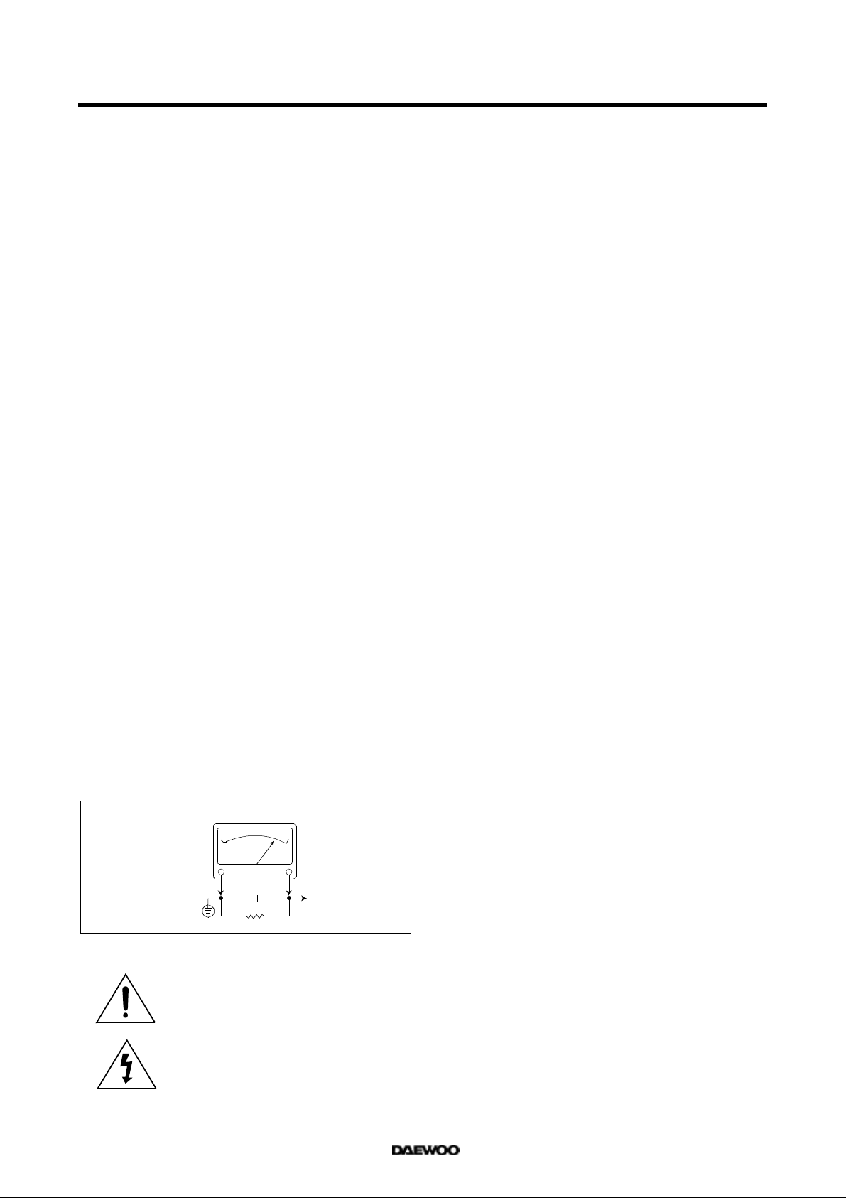
7. AFTER RE-ASSEMBLY OF THE STE ALWAYS PERFORM AN A.C. LEAKAGE
TEST ON ALL EXPOSED METALLIC PARTS OF THE CABINET. (THE CHANNEL SELECTOR KNOB, ANTENNA TERMINALS, HANDLE AND SCREWS) TO
BE SURE THE SET IS SAFE TO OPERATE WITHOUT DANGER OF ELECTRICAL SHOCK. DO NOT USE A LINE ISOLATION TRANSFORMER DURING
THIS TEST USE AN A.C. VOLTMETER, HAVING 5000 OHMS PER VOLT OR
MORE SENSITIVITY, IN THE FOLLOWING MANNER : CONNECT A 1500 OHM
10 WATT RESISTOR, PARALLELED BY A .15 MFD. 150V A.C. TYPE CAPACITOR BETWEEN A KNOWN GOOD EARTH GROUND (WATER POPE, CONDUIT, ETC.) AND THE EXPOSED METALLIC PARTS, ONE AT A TIME.
MEASURE THE A.C. VOLTAGE ACROSS THE COMBINATION OF 1500 OHM
RESISTOR AND .15 MFD CAPACITOR. REVERSE THE A.C. PLUG AND
REPEAT A.C. VOLTAGE MEASUREMENTS FOR EACH EXPOSED METALLIC
PART. VOLTAGE MEASURED MUST NOT EXCEED .75 VOLTS R.M.S THIS
CORRESPONDS TO 0.5 MILLIAMP A.C. NAY VALUE EXCEEDING THIS LIMIT
CONSTITUTES A POTENTIAL SHOCK HAZARD AND MUST BE CORRECTED
IMMEDIATELY.
A.C. VOLTMETER
0.15 uF
GOOD EARTH GROUND
SUCH AS THE WATER
PIPE, CONDUIT, ETC.
1500 OHM
10WATT
PLACE THIS PROBE
ON EACH EXPOSED
METAL PART
SUBJECT : GRAPHIC SYMBOLS
THE LIGHTNING FLASH WITH ARROWHEAD SYMBOL,
WITHIN AN EQUILATERAL TRIANGLE, IS INTENDED
TO ALERT THE SERVICE PERSONNEL TO THE PRESENCE OF UNINSULATED “DANGEROUS VOLTAGE”
THAT MAY BE OF SUFFICIENT MAGNITUDE TO CONSTITUTE A RISK OF ELECTRIC SHOCK.
THE EXCLAMATION POINT WITHIN AN EQUILATERAL
TRIANGLE IS INTENDED TO ALERT THE SERVICE
PERSONNEL TO THE PRESENCE OF IMPORTANT
SAFETY INFORMATION ON SERVICE LITERATURE.
SUBJECT : X-RADIATION
1. BE SURE PROCEDURES AND INSTRUCTIONS TO ALL SERVICE PERSONNEL COVER THE SUBJECT OF X-RADIATION. THE ONLY POTENTIAL
SOURCE OF X-RAYS IN CURRENT T.V. RECEIVERS IS THE PICTURE TUBE.
HOWEVER, THIS TUBE DOES NOT EMIT X-RAYS WHEN THE HIGH VOLTAGE IS AT THE FACTORY SPECIFIED LEVEL. THE PROPER VALUE IS
GIVEN IN THE APPLICABLE SCHEMATIC. OPERATION AT HIGHER VOLTAGES MAY CAUSE A FAILURE OF THE PICTURE TUBE OR HIGH VOLTAGE
SUPPLY AND UNDER CERTAIN CIRCUMSTANCES, AMY PRODUCE RADIATION IN EXCESS OF DESIRABLE LEVELS.
2. ONLY FACTORY SPECIFIED C.R.T ANODE CONNECTORS MUST BE USED.
DEGAUSSING SHIELDS ALSO SERVE AS X-RAY SHIELD IN COLOR SETS.
ALWAYS RE-INSTALL THEM.
3. IT IS ESSENTIAL THAT SERVICE PERSONNEL HAVE AVAILABLE AN ACCURATE AND RELIABLE HIGH VOLTAGE METER. THE CALIBRATION OF THE
METER SHOULD BE CHECKED PERIODICALLY AGAINST A REFERENCE
STANDARD. SUCH AS THE ONE AVAILABLE AT YOUR DISTRIBUTOR.
4. WHEN THE HIGH VOLTAGE CIRCUITRY IS OPERATING PROPERLY THERE
IS NO POSSIBILITY OF AN X-RADIATION PROBLEM. EVERY TIME A COLOR
CHASSIS IS SERVICED, THE BRIGHTNESS SHOULD BE RUN UP AND
DOWN WHILE MONITORING THE HIGH VOLTAGE WITH A METER TO BE
CERTAIN THAT THE HIGH VOLTAGE DOES NOT EXCEED THE SPECIFIED
VALUE AND THAT IT IS REGULATING CORRECTLY. WE SUGGEST THAT
YOU AND YOUR SERVICE ORGANIZATION REVIEW TEST PROCEDURES
SO THAT VOLTAGE REGULATION IS ALWAYS CHECKED AS A STANDARD
SERVICING PROCEDURE, AND THAT THE HIGH VOLTAGE READING BE
RECORDED ON EACH CUSTOMER’S INVOICE.
5. WHEN TROUBLESHOOTING AND MAKING TEST MEASUREMENTS IN A
PRODUCT WITH A PROBLEM OF EXCESSIVE HIGH VOLTAGE, AVOID
BEING UNNECESSARILY CLOSE TO THE PICTURE TUBE AND THE HIGH
VOLTAGE SUPPLY. DO NOT OPERATE THE PRODUCT LONGER THAN IS
NECESSARY TO LOCATE THE CAUSE OF EXCESSIVE VOLTAGE.
6. REFER TO HV, B+ AND SHUTDOWN ADJUSTMENT PROCEDURES
DESCRIBED IN THE APPROPRIATE SCHEMATIC AND DIAGRAMS (WHERE
USED).
SUBJECT : IMPLOSION
1. ALL DIRECT VIEWED PICTURE TUBES ARE EQUIPPED WITH AN INTEGRA
IMPLOSION PROTECTION SYSTEM. BUT CARE SHOULD BE TAKEN TO
AVOID DAMAGE DURING INSTALLATION. AVOID SCRATCHING THE
TUBE. OF SCRATCHED REPLACE IT.
2. USE ONLY RECOMMENDED FACTORY REPLACEMENT TUBES.
SUBJECT : TIPS ON PROPER INSTALLATION
1. NEVER INSTALL ANY PRODUCT IN A CLOSED-IN RECESS, CUBBYHOLE OR
CLOSELY FITTING SHELF SPACE, OVER OR CLOSE TO HEAT DUCT, OR IN
THE PATH OF HEATED AIR FLOW.
2. AVOID CONDITIONS OF HIGH HUMIDITY SUCH AS: OUTDOOR PATIO
INSTALLATIONS WHERE DEW IS A FACTOR, NEAR STEAM RADIATORS
WHERE STEAM LEAKAGE IS A FACTOR, ETC.
3. AVOID PLACEMENT WHERE DRAPERIES MAY OBSTRUCT REAR VENTING.
THE CUSTOMER SHOULD ALSO AVOID THE USE OF DECORATIVE
SCARVES OR OTHER COVERINGS WHICH MIGHT OBSTRUCT VENTILATION.
4. WALL AND SHELF MOUNTED INSTALLATIONS USING A COMMERCIAL
MOUNTING KIT, MUST FOLLOW THE FACTORY APPROVED MOUNTING
INSTRUCTIONS. A PRODUCT MOUNTED TO A SHELF OR PLATFORM MUST
RETAIN ITS ORIGINAL FEET (OR THE EQUIVALENT THICKNESS IN SPACERS)TO PROVIDE ADEQUATE AIR FLOW ACROSS THE BOTTOM, BOLTS
OR SCREWS USED FOR FASTENERS MUST NOT TOUCH ANY PARTS OR
WIRING. PERFORM LEAKAGE TEST ON CUSTOMIZED INSTALLATIONS.
5. CAUTION CUSTOMERS AGAINST THE MOUNTING OF A PRODUCT ON
SLOPING SHELF OR A TILTED POSITION, UNLESS THE PRODUCT IS
PROPERLY SECURED.
6. A PRODUCT ON A ROLL-ABOUT CART SHOULD BE STABLE ON ITS MOUNTING TO THE CART. CAUTION THE CUSTOMER ON THE HAZARDS OF TRYING TO ROLL A CART WITH SMALL CASTERS ACROSS THRESHOLDS OR
DEEP PILE CARPETS.
7. CAUTION CUSTOMERS AGAINST THE USE OF A CART OR STAND WHICH
HAS NOT BEEN LISTED BY UNDERWRITERS LABORATORIES. INC. FOR
USE WITH THEIR SPECIFIC MODEL OF TELEVISION RECEIVER OR
GENERICALLY APPROVED FOR USE WITH T.V.S OF THE SAME OR
LARGER SCREEN SIZE.
8. CAUTION CUSTOMERS AGAINST THE USE OF EXTENSION CORDS,
EXPLAIN THAT A FOREST OF EXTENSIONS SPROUTING FROM A SINGLE
OUTLET CAN LEAD TO DISASTROUS CONSEQUENCES TO HOME AND
FAMILY.
2
PRODUCT SAFETY SERVICING GUIDELINES FOR COLOR TELEVISION RECEIVERS
CAUTION : Do not attempt to modify this product in any way. Unauthorized modifications will not only void the warranty, but may lead to
your being liable for any resulting property damage or user injury.
Service work should be performed only after you are thoroughly
familiar with all of the following safety checks and servicing guidelines. To do otherwise, increases the risk of potential hazards and
injury to the user.
SAFETY CHECKS
After the original service problem has been corrected, a check should
be made of the following:
SUBJECT : FIRE & SHOCK HAZARD
1. Be sure that all components are positioned in such a way as to
avoid possibility of adjacent component shorts. This is especially
important on those chassis which are transported to and from the
repair shop.
2. Never release a repair unless all protective devices such as insulators, barriers, covers, shields, strain reliefs, and other hardware
have been reinstalled per original design.
3. Soldering must be inspected to discover possible cold solder joints,
frayed leads, damaged insulation (including A.C. cord), solder
splashes or sharp solder points. Be certain to remove all loose foreign particals.
4. Check for physical evidence of damage or deterioration to parts
and components, and replace if necessary follow original layout,
lead length and dress.
5. No leads or components should touch a receiving tube or a resistor
rated at 1 watt or more. Lead tension around protruding metal surfaces must be avoided.
6. All critical components such as fuses, flameproof resistors, capacitors, etc. must be replaced with exact factory types. Do not use
replacement components other than those specified or make
unrecommended circuit modifications.
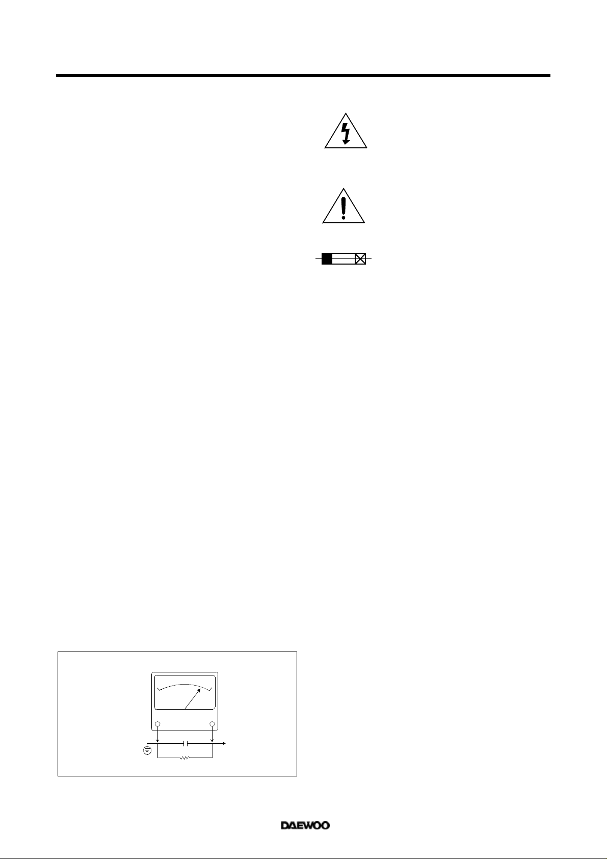
7. After re-assembly of the set always perform an A.C. leakage test
on all exposed metallic parts of the cabinet, (the channel selector
knob, antenna terminals, handle and screws) to be sure the set is
safe to operate without danger of electrical shock. Do not use a
line isolation transformer during this test. Use an A.C. voltmeter,
having 5000 ohms per volt or more sensitivity, in the following
manner : connect a 1500 ohm 10 watt resistor, paralleled by a 15
mfd. 150V A.C. type capacitor between a known good earth
ground (9water pipe, conduit, etc.) and the exposed metallic parts,
one at a time. Measure the A.C. voltage across the combination of
1500 ohm resistor and 0.15 MFD capacitor. Reverse the A.C. plug
and repeat A.C. voltage measurements for each exposed metallic
part. Voltage measured must not exceed 0.75 volts R.M.S. This
corresponds to 0.5 milliamp A.C. Any value exceeding this limit
constitutes a potential shock hazard and must be corrected immediately.
A.C. VOLTMETER
GRAPHIC SYMBOLS :
The lightning flash with arrowhead symbol,
within an equilateral triangle, is intended to alert
the service personnel to the presence of uninsulated “dangerous voltage” that may be of sufficienty magnitude to constitute a risk of electric
shock.
The exclamation point within an equilateral triangle is intended to alert the service personnel
to the presence of important safety information
in service literature.
Fuse symbol is printed on pcb adjacent to the
fuse, with “RISK OF FIRE REPLACE FUSE AS
MARKED”. The symbol is explained in the service manual with the following wording or equivalent.
“CAUTION :
FOR CONTINUED PROTECTION AGAINST FIRE
HAZARD, REPLACE ONLY WITH SAME TYPE (4A, 125V)” and
“
ATTENTION
: AFIN D’ASSU UNE PROTECTION PERMANENTE
CONTRE LES RISQUES D’INCENDIE, REMPLACER UNIQUEMENT PAR UN FUSIBLE DE MEME TYPE ET DE ”4A, 125V”.
SUBJECT : X-RADIATION
1. Be sure procedures and instructions to all service personnel cover
the subject of X-rays in current T.V. receivers is the picture tube.
However, this tube does not emit X-rays when the high voltage is
at the factory specified level. The proper value is given in the applicable schematic. Operation at higher voltages may cause a failure
of the picture tube or high voltage supply and, under certain circumstances, may produce radiation in excess of desirable levels.
2. Only factory specified C.R.T. anode connectors must be used.
Degaussing shields also serve as X-ray shield in color sets.
Always re-install them.
3. It is essential that the serviceman has available an accurate and
reliable high voltage meter. The calibration of the meter should be
checked perio - dically against a reference standard. Such as the
one available at your distributor.
4. When the high voltage circuitry is operating properly there is no
possibility of an X-radiation problem. Every time a color chassis is
serviced, the brightness should be run up and down while monitoring the high voltage with a meter to be certain that the high voltage
does not exceed the specified value and that it is regulating correctly. We suggest that you and your service organization review
test procedures so that voltage regulation is always checked as a
standard servicing procedure. And that the high voltage reading be
recorded on each customer’s invoice.
5. When troubleshooting and making test measurements in a receiver
with a problem of excessive high voltage, avoid being unnecessarily
close to the picture tub eand the high voltage compartment.
Do not operate the chassis longer than is necessary to locate the
cause of excessive voltage.
6. Refer to HV, B+and Shutdown adjustment procedures described in
the appropriate schematic and diagrams(where used).
Good earth ground,
such as the water
pipe, conduit, etc.
0.15 uF
1500 OHM
10WATT
Place this probe
on each exposed
metal part.
3

SUBJECT : IMPLOSION
1. All direct viewed picture tubes are equipped with an integral implosion protection system, but care should be taken to avoid damage
during installation. Avoid scratching the tube. If scratched, replace
it.
2. Use only recommended factory replacement tubes.
SUBJECT : TIPS ON PROPER INSTALLATION
1. Never install any receiver in closed-in recess, cubbyhole or closely
fitting shelf space over, or close to heat duct, or in the path of
heated air flow.
2. Avoid conditions of high humidity such as : Outdoor patio installations where dew is a factor. Near steam radiators where steam
leakage is a factor, etc.
3. Avoid placement where draperies may obstruct rear venting. The
customer should also avoid the use of decorative scarves or other
coverings which might obstruct ventilation.
4. Wall and shelf mounted installations using a commercial mounting
kit, must follow the factory approved mounting instructions. A
receiver mounted to a shelf or platform must retain its original
feet(or the equivalent thickness in spacers) to provide adequate
are flow across the bottom, bolts or screws used for fasteners
must not touch and parts or wiring. Perform leakage test on customized installations.
5. Caution customers against the mounting of a receiver on sloping
shelf or a tilted position, unless the receiver is properly secured.
6. A receiver on a roll-about cart should be stable on its mounting to
the cart. Caution the customer on the hazards of trying to roll a cart
with small casters across thresholds or deep pile carpets.
7. Caution customers against the use of a cart or stand which has not
been listed by underwriters laboratories, inc. For use with their
specific model of television receiver or generically approved for
use with T.V.’s of the same or larger screen size.
4
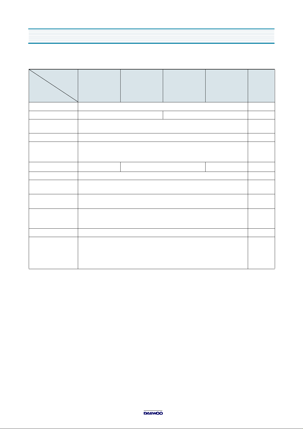
SPECIFICATIONS
DTQ-14/20V1FC
MODEL
ITEMS
TV STANDARD NTSC-M
POWER INPUT AC 120V 60 Hz AC 220V 50/60 Hz
POWER CONSUMPTION
TUNING SYSTEM Frequency Synthesizer ( FS ) Tuning System
TUNING RANGES
DTQ-14V5/20V4FC
DTQ-14/20V1FS
DTQ-14V5/20V4FS
DTQ-14/20V3FS
DTQ-14/20U1FS DTQ-14/20U1FSP
14 = 55W
20 = 65W
VHF : 2 ~ 13 (12)
UHF : 14 ~ 69 (56)
CATV : 1 ~ 125 (125)
DTQ-14/20V1FSP
DTQ-14V5/20V4FSP
REMARKS
SOUND OUTPUT 1.3 W 1.3 W+1.3 W
SPEAKER 3 W 8 ohm
ANTENNA INPUT
IMPEDANCE
AUXILIARY
INPUT TERMINAL
INTERMEDIATE
FREQUENCIES
REMOTE CONTROL R-38T01
SPECIAL FUNCTIONS
Picture IF Carrier Frequency : 45.75 MHz
Sound IF Carrier Frequency : 41.25 MHz
Color Sub-Carrier Frequency : 42.17 MHz
75 ohm Unbalanced
Front : Video, Audio
Rear : Video, Audio
3-Language OSD
With CAPTION
Wake-up On/Off Time
Sleep Timer
Power Restore
1.3 W
5
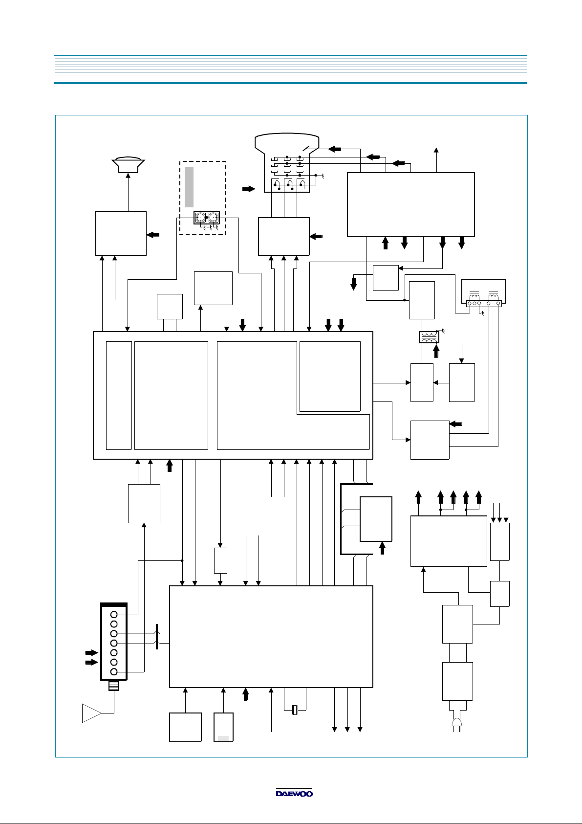
BLOCK DIAGRAM
CRT
ABL
SPEAKER
OPTION
2
I601
4
A. MUTE
AUDIO
1
I101
1
TDA7267A
3
EXT. AUD IN
51
AUDIO DEMOD/VOL CONTROL
SOUND 12V
EXT. AUDIO
Z501
VCO
L501
VOIL
V. OUT
49
48
46
VIF
PLL
AFT
AGC
DEMOD
5
6
4
10
HEATER
A/V JACK
9
8
7
I901
1
TDA6103Q
EXT. VIDEO
TRAP
4.5MHz
VIDEO/VER.
VCC (5V)
RED
V. IN
EXT. V IN
44
43
42
192021
CHROMA/
PROCESS
LUMINANCE
34
6
2
3
GREEN
BLUE
14
13
200V
HOR/BUS VCC25
FBP
28
/VERTICAL
HORIZONTAL
15
16
H.V.
FOCUS
SCREEN
Hcp
133V
VIDEO
(200V)
HEATER
10V
25.5V
(VER. B+)
(RGB 9V/TUNER 5V)
VERT.
I401
7805
C
5V
RGB VCC
IF/VIDEO
18
PROCESS
17
27
23
VER. OUT
12
11
Q402
HOR. OUT
B
T401
45V
C
B
5
C
Q401
HOR. DR
6
I301
LA7841
HOR.
U-COM
#37
B
HOR
Q403
ON/OFF
VER. B+
SDA
ABL
V.SYNC21H.SYNC
20
12ST-BY 5V
X-RAY
OSD BLANK
OSD GREEN
OSD BLUE
OSD RED
24
23
22
I701
MICROCOMPUTER
17
10
11
RESET (L)
PW ON(H)
32.768KHz
X701
5V
IF VCC
SAW
SF101
FILTER
RF AGC
15
AGC
U102
TUNER
29 30
SDA SCK
33V 5V
IF
ANTENNA
RF INPUT
13
POWER
CH +/-
CVBS
AFT
Q703
14
19 40
34
PRE
VOL +/-
MENU
AMP
SCK
5 6
I703
EEPROM
SDA SCK
SDA
25
42
40
A.MUTE(H)
8
SCK
ST-BY 5V
27
28
37
H.OUT(L)
133V
45V
T801
D801
L801
60Hz
AC 120V
SOUND 12V
33V
ST-BY 5V
133V
12V
PW ON(H)
I801
SMPS TRANS
DIODE
BRIDGE
LINE
FILTER
DPM001T1
S
D
FET
Q801
G
6
ALIGNMENT INSTRUCTIONS
1. SERVICE MODE ADJUSTMENTS
Follow the steps below whenever service adjustment is required. See Table- A and Table- B to determine if
service adjustments are required.
1) How to enter the service mode using the user remote control.
•
Turn the set on.
•
Direct the remote control to the reception window of TV.
•
Push buttons of remote control in sequence as follows.
1 → MUTE → DISPLAY → MUTE
•
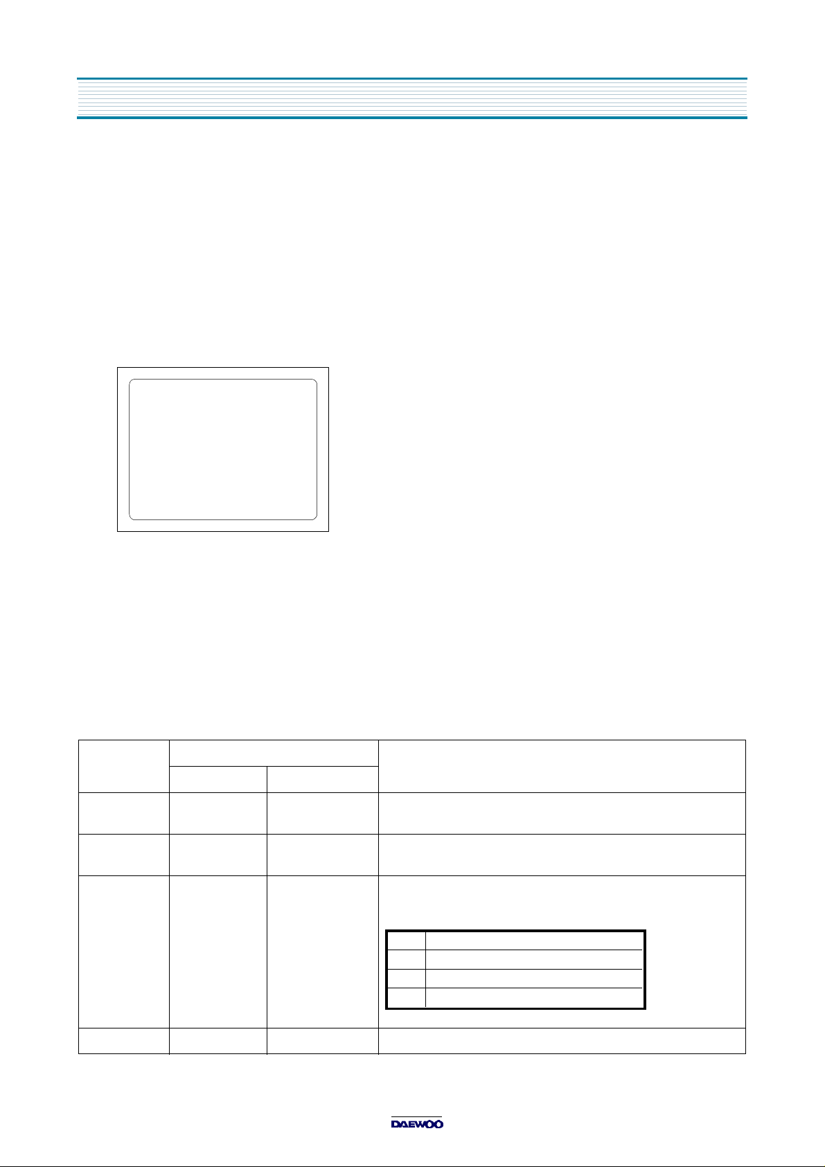
Then, the screen will appear as follows.
S2 SCRN
S5 IFC
S6 GEO
S8 W/B
S9 DP
S12 FACT
S7 PTRN NORMAL
•
Using the channel up or channel down button, select the item you wish to adjust.
(The color of selected item turns into the red.)
•
Press the volume up or down button to enter in the service mode you wish to adjust.
2) How to memorize the adjusted values in the service mode.
•
Must press
DISPLAY
button the state which the screen is displaying each of service
after all adjustments are completed each of all service menu.
Table-A : Adjust the values of service mode when a part is replaced.
PART
REPLACED
I701
(U-COM)
I101
(MAIN)
I703
(EEPROM)
NECESSARY UNNECESSARY
ADJUSTMENT
O
O
O
Data is stored in I703.
Initial setting values are written from I701.
Adjusting Items
S5 RFAGCD
S6 H.PHASE/V.POSI/V.SIZE
S8 RD/BD/RB/GB/BB
S9 Subbrightness
menus
NOTES
CRT O Adjust items related to picture tube only.(White Balance adjustment)
7
ALIGNMENT INSTRUCTIONS
Table-B
MODE ADJUSTMENT ITEMS
S2 Screen Adjustment - -
Auto RF AGC - Video Level (VIDEOL) 7 0 ~ 7 Must be set to 7
RF AGC Delay (RFAGCD) * 0 ~ 63 Align RF AGC threshold
S5
S6
S7
S8
S9
S12 Forwarding Mode - Factory Initialization
FM Level (FM.LEV) 8 0 ~ 31 Must be set to 20
AGC Point 3.75 - Select AGC reference voltage
A/D VALUE - Horizontal Phase(H.PHASE) * 0 ~ 31 Align sync to flyback pulse, using internal cross pattern(S7)
Vertical Position (V.POSI) * 0 ~ 63 Align vertical DC bias, using internal cross pattern(S7)
Vertical Size (V.SIZE) * 0 ~ 127 Align vertical amplitude, using internal cross pattern(S7)
NO SD POWER OFF YES - Automatically turn off in 15min for no received signal.
Vertical S-Correction (V SC) 0 0 ~ 31 Must be set to 6
Vertical Linearity (V LIN) 20 0 ~ 31 Must be set to 16
Internal Black - - Display internal BLACK pattern
Internal 100% White - - Display internal 100% WHITE
Internal 60% White - - Display internal 60% WHITE
Internal Cross Pattern - - Display internal CROSS pattern
Red Drive (RD) * 0 ~ 127 Align RED OUT AC level
Green Drive (GD) 10 0 ~ 15 Must be set to 10
Blue Drive (BD) * 0 ~ 127 Align BLUE OUT AC level
Red Bias (RB) * 0 ~ 255 Align RED OUT DC level
Green Bias (GB) * 0 ~ 255 Align GREEN OUT DC level
Blue Bias (BB) * 0 ~ 255 Align BLUE OUT DC level
Subbrightness * 0 ~ 127 Align common RGB DC level
Contrast 10 0 ~ 27
Tint 27 0 ~ 27
Color 15 0 ~ 27
DATA
INITIAL RANGE
REMARKS
*
indicates the items with different settings each of sets
2. ASSEMBLY ADJUSTMENTS
1) SCREEN ADJUSTMENT (S2)
•
Enter the service mode and select service adjustment S2.
•
You cna see the one horizontal line on the screen.
•
Adjust the Screen Control Volume (located on FBT) so that the horizontal line onscreen may be
disappeared.
•
Press the volume up or down button to exit in the screen adjustment mode.
NOTE
IN THE SCREEN ADJUSTMENT MODE, DONT PRESS OTHER BUTTONS EXCEPT VOLUME UP OR DOWN BUTTON.
8

2) FOCUS ADJUSTMENT
•
Turn in a local station and adjust the Focus Control knob (located on FBT) for best picture
details at high light condition.
3) RF AGC DELAY ADJUSTMENT (S5)
•
Receive a good local channel.
•
Enter the service mode and select service adjustment S5.
•
You can see the OSD as shown in below.
IF CONTROL
AUTO RFAGC START
VIDEOL 7
RFAGCD 10
FM.LEV 8
AGC POINT 3.75
A/D VALUE : 8DH
¡ã¡åMOVE ¢¸¢ºADJUST RECALL : SET
ALIGNMENT INSTRUCTIONS
•
Select RFAGCD item, press the volume up or down button until noise or beat in picture disappears.
•
Press the DISPLAY button to memorize the data.
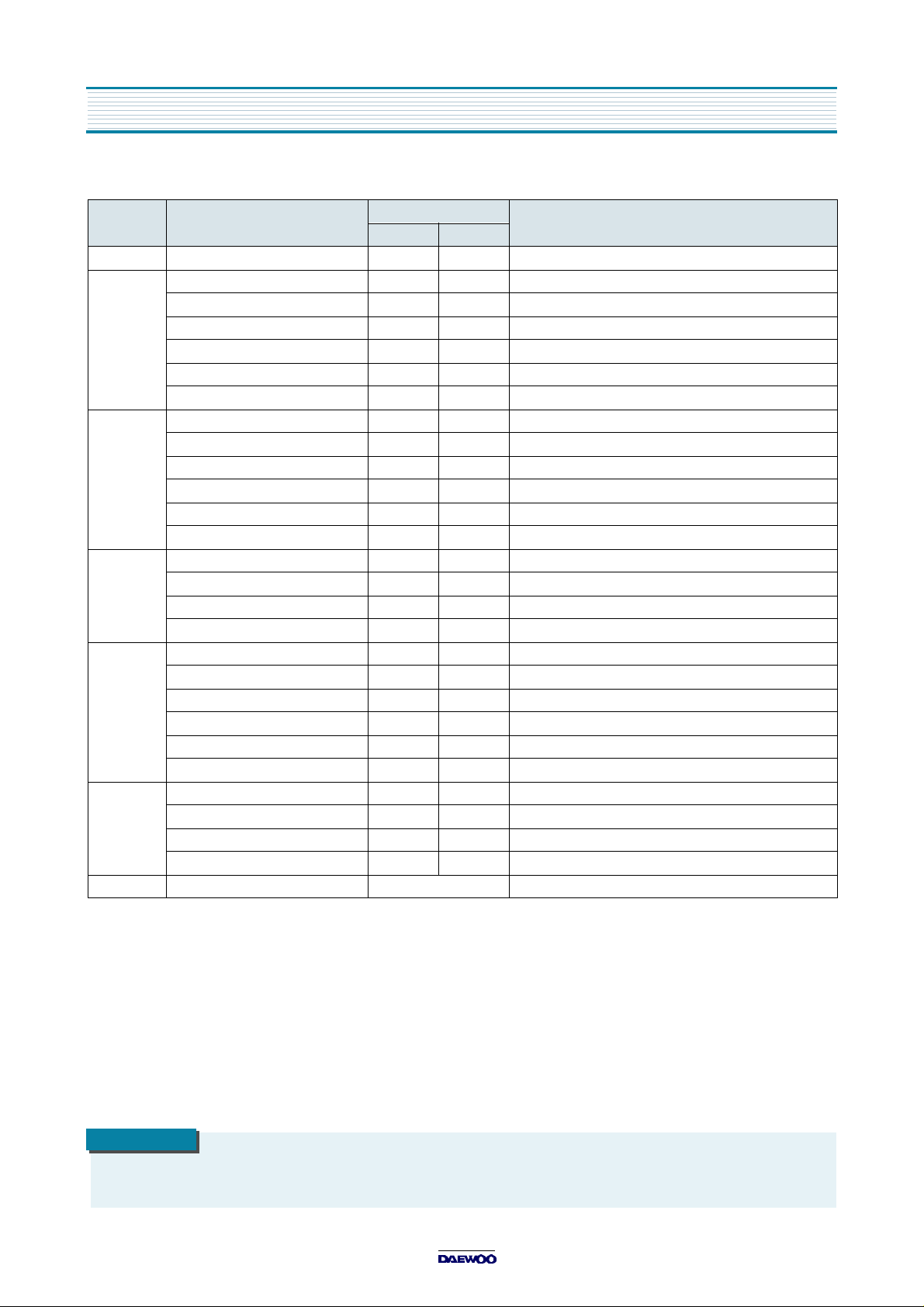
4) GEOMETRIC ADJUSTMENTS (S6)
•
Enter the service mode and select service adjustment S7.
•
Whenever you select the “S7” using the volume up or down button, the screen is changing like this.
NORMAL BLACK WHITE100 WHITE60 CROSS
•
Using the volume up or down button, select internal cross pattern.
•
Select service adjustment S6
•
You can see the OSD as shown in below.
GEOMETRY
H. PHASE 20
V. POSI 29
V. SIZE 70
NO SD POWER OFF YES
V SC 0
V LIN 20
¡ã¡åMOVE ¢¸¢ºADJUST RECALL : SET
4-1. Horizontal Position Adjustment
•
Select H.PHASE item, adjust H.PHASE data value to obtain proper horizontal centering of the
internal cross pattern at the left and right of the screen.
4-2. Vertical Position Adjustment
•
Select V.POSI item, adjust V.POSI data value to center the raster properly on thescreen.
9
ALIGNMENT INSTRUCTIONS
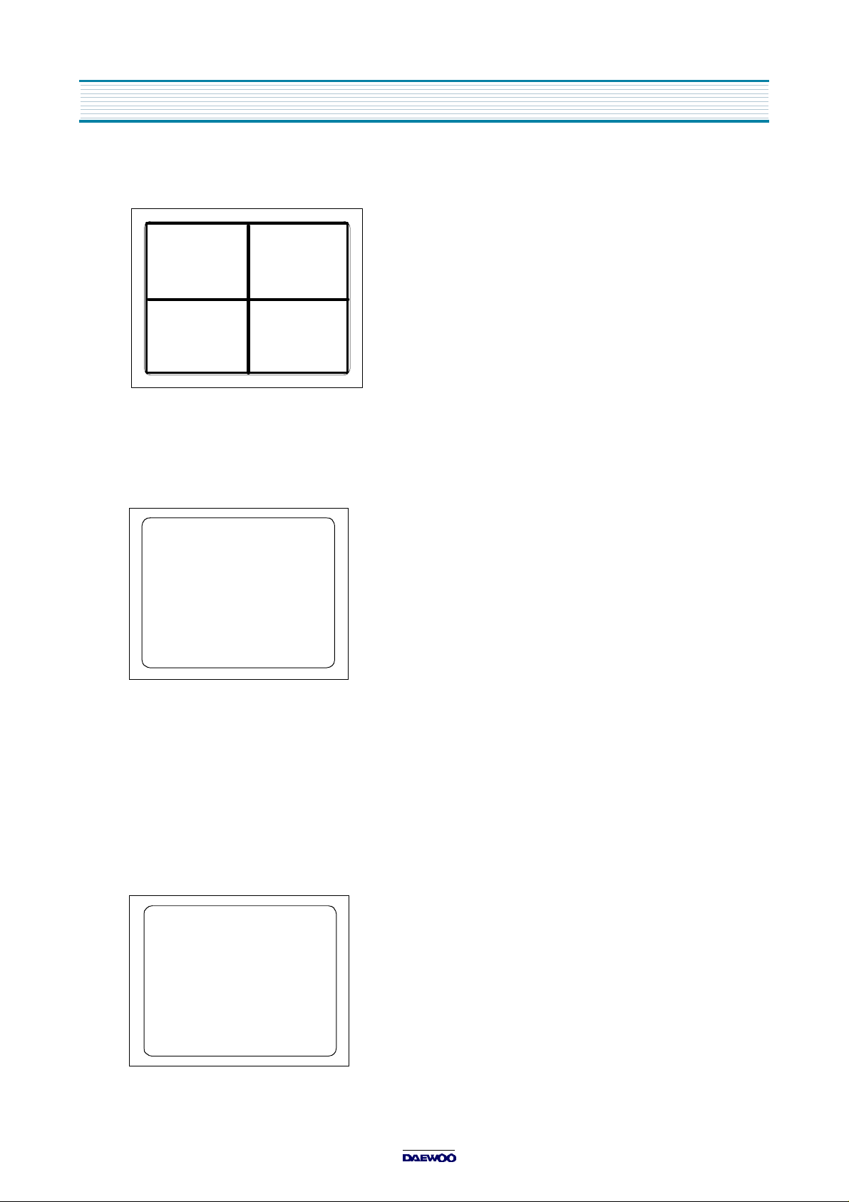
4-3. Vertical Size Adjustment
•
Select “V.SIZE” item, adjust “V.SIZE” data value to proper vertical size as follows.
5) WHITE BALANCE ADJUSTMENT(S8)
•
Receive a good local channel.
•
Enter the service mode and select service adjustment S8.
•
You can see the OSD as shown in below.
RD 58
GD 10
BD 65
RB 105
GB 160
BB 100
¡ã¡åMOVE ¢¸¢ºADJUST RECALL : SET
•
Using volume up or volume down, adjust service adjustment data of RD/GD/BD and RB/GB/BB until a good gray
scale with normal whites is obtained.ALIGNMENT INSTRUCTIONS
•
Press the DISPLAY button to memorize the data.
6) DIGITAL PRESET(D.P) ADJUSTMENTS(S9)
SUBBRIGHTNESS ADJUSTMENT
•
Receive a good local channel.
•
Enter the service mode and select service adjustment S9.
•
You can see the OSD as shoown in below.
D.P.
SUB BRIGHTNESS 64
CONTRAST 10
TINT 27
COLOR 15
¡ã¡åMOVE ¢¸¢ºADJUST RECALL : SET
10

•
Select Subbrightness item, adjust Subbrightness data value
•
Press the DISPLAY button to memorize the data.
CONTRAST
•
Fixed value = 10
TINT
•
Fixed value = 27
COLOR
•
Fixed value = 15
7) FACTORY OUTGOING MODE (S12 : FACT)
•
If you select the S12, then the set becomes factory outgoing status.
•
You can see the OSD “outgoing OK”
ALIGNMENT INSTRUCTIONS
to obtain normal
brightness level.
11
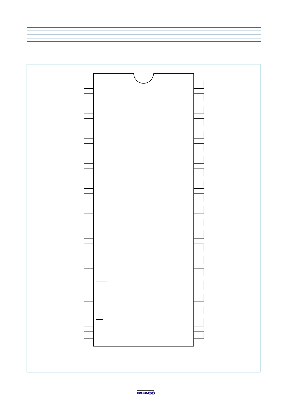
IC DESCRIPTION
U-COM(I701)
CABLE (H)
ST / MONO
BLUE BACK
NC
AUTO TINT
NC
1
P10
2
P11
3
P12
4
P13/PWM1
5
P14/PWM2
6
P15/PWM3
7
P16
8
P17/PWM
9
VSS
10
XT1
11
XT2
12
VDD
P07TV ONLY (H)
P06
P05
P04
P03
P02
P01
P00
P73/INT3/TOIN
P72/INT2/TOIN
P71/INT1
P70/INT0
42
POWER ON(H)
41
NC
40
AUDIO MUTE(H)
39
38
37
36
35
34
33
32
31
AKB WHITE
SOUND RESET
H.OUT
ON(L)/OFF(H)
POWER ON
ST-BY(H)
REMOCON IN
NC
NC
NC
13
KEY IN
AFT IN
AGC IN
SPARE A/D M-DATA
P84/AN4
14
P85/AN5
15
P86/AN6
16
P87/AN7
17
RES
18
FILT
19
CVIN
20
VS
21
HS R
- X'TAL : 32.768 KHz
P63/SCLK1
P62/SDA1
P61/SCLK0
P60/SDA0
BL
B
G
30
T-CLOCK
29
T-DATA
28
M-CLOCK
27
26
I
25
24
23
22
12

IC DESCRIPTION
1. Abstract.
This specification is 1-Tuner Mono Model for North/South America, CCD 1-Chip MICOM LC863228A.
It is developing software specification for tuning only NTSC and 3 system TV F/S.
* 3 System : NTSC-M, PAL-M, PAL-N.
2. H/W Outline.
1) ROM : 28,672 x 8bits.tsc
: 15,872 x 8 bits for CGROM.
2) RAM : 512 x 8bits.
: 336 x 9bits.(for CRT Display)
3) OSD Function.
¡¤
Screen Display. : 34 characters x 16 lines.(by software)
¡¤
RAM : 336 words. (9 bits per word)
Display area. : 34 words. x 8 lines.
1st control area. : 8 words. x 8 lines.
¡¤
Characters.
244 patterns programmable.
Up to 244 kinds of 16 x 17 dot characters.
Up to 244 kinds of 8 x 9 dot characters.
or
Up to 244 kinds of 16 x 32 dot characters used 16K bytes.
¡¤
Various characters attributes.
Character colors. : 16 colors
Character background colors. : 16 colors
Fringe / shadow colors. : 16 colors
Full screen colors. : 16 colors
Rounding.
Underline.
Italic character.(slanting)
¡¤
Attribute can be changed without spacing.
¡¤
Vertical display start line number can be set for each row independently.(Row can be overlapped.)
¡¤
Horizontal display start position can be set for each row independently.
¡¤
Different display modes can be set for each row independently.
Caption and Text mode/ OSD mode 1/ OSD mode 2(Quarter size)/ Simplified graphic mode.
¡¤
Ten character sizes.
Horiz. x Vert. = (1x1),(1x2),(2x2),(2x4),(0.5x0.5)
(1.5x1),(1.5x2),(3x2),(3x4),(0.75x0.5)
¡¤
Shuttering and scrolling on each row.
3. System Feature.
1) The system for TV tuning is Frequency Synthesis type.
2) Closed Captions function is interior designed.
13
 Loading...