


Daewoo 450, 460, D20S-3(B3.3), D30S-3(B3.3), D25S-3(B3.3) user guide
...SB4135E00
J a n . 2 0 0 4
Service Manual
B3.3 Diesel Engine
Lift Trucks
D20S-3(B3.3), D25S-3(B3.3), D30S-3(B3.3),
D32S-3(B3.3), D33S-3(B3.3)
Skid Steer Loaders 450/450Plus, 460/460Plus

Important Safety Information
Most accidents involving product operation, maintenance and repair are caused by failure to observe basic safety rules or precautions. An accident can often be avoided by recognizing potentially hazardous situations before an accident occurs. A person must be alert to potential hazards. This person should also have the necessary training, skills and tools to perform these functions properly.
Read and understand all safety precautions and warnings before operating or performing lubrication, maintenance and repair on this product.
Basic safety precautions are listed in the “Safety” section or the Service or Technical Manual. Additional safety precautions are listed in the “Safety” section of the owner/operation/maintenance publication.
Specific safety warnings for all these publications are provided in the description of operations where hazards exist. WARNING labels have also been put on the product to provide instructions and to identify specific hazards. If these hazard warnings are not heeded, bodily injury or death could occur to you or other persons. Warnings in this publication and on the product labels are identified by the following symbol.
 WARNING
Improper operation, lubrication, maintenance or repair of this product can be dangerous and could result in injury or death.
Do not operate or perform any lubrication, maintenance or repair on this product, until you have read and understood the operation, lubrication, maintenance and repair information.
Operations that may cause product damage are identified by NOTICE labels on the product and in this publication.
DAEWOO cannot anticipate every possible circumstance that might involve a potential hazard. The warnings in this publication and on the product are therefore not all inclusive. If a tool, procedure, work method or operating technique not specifically recommended by DAEWOO is used, you must satisfy yourself that it is safe for you and others. You should also ensure that the product will not be damaged or made unsafe by the operation, lubrication, maintenance or repair procedures you choose.
The information, specifications, and illustrations in this publication are on the basis of information available at the time it was written. The specifications, torques, pressures, measurements, adjustments, illustrations, and other items can change at any time. These changes can affect the service given to the product.
Obtain the complete and most current information before starting any job. DAEWOO dealers have the most current information available.
1
Index |
|
Introduction |
|
About the Manual................................................... |
4 |
How to Use the Manual ......................................... |
4 |
Illustrations............................................................. |
6 |
Symbols ................................................................. |
5 |
Engine Identification |
|
Engine Diagrams ................................................... |
9 |
Engine Views....................................................... |
9 |
Engine Identification .............................................. |
7 |
Engine Dataplate ................................................. |
7 |
Specifications......................................................... |
8 |
Troubleshooting Symptoms |
|
Procedures and Techniques ................................. |
20 |
Troubleshooting Symptoms Charts....................... |
20 |
Coolant Contamination ....................................... |
34 |
Coolant Loss....................................................... |
35 |
Coolant Temperature above Normal................... |
38 |
Engine Cranks But Will Not Start |
|
(No Exhaust Smoke) .......................................... |
22 |
Engine Difficult to Start or Will Not Start |
|
(Exhaust Smoke) (Continued) ............................ |
24 |
Engine Difficult to Start or Will Not Start |
|
(Exhaust Smoke) ................................................ |
23 |
Engine Has Poor Respones ............................... |
25 |
Engine Power Output Low (Continued) .............. |
29 |
Engine Power Output Low.................................. |
28 |
Engine Runs Rough or Misfires.......................... |
27 |
Engine Stops During Operation .......................... |
26 |
Engine Vibration Excessive ................................ |
41 |
Engine Will Not Crank or Cranks Slowly ............ |
21 |
Excessive Exhaust (Black Smoke) ..................... |
30 |
Excessive Noise (Continued) ............................. |
40 |
Excessive Noise ................................................. |
39 |
Fuel consumption Is Excessive .......................... |
33 |
Lubricating Oil Consumption Excessive ............. |
31 |
Lubricating Oil Contaminated ............................. |
32 |
Lubricating Oil Pressure Is Low.......................... |
36 |
Oil Level Rises.................................................... |
37 |
Complete Engine |
|
Complete Engine .................................................. |
42 |
Engine Assembly ................................................ |
61 |
Engine Disassembly ........................................... |
42 |
Engine Testing |
|
Complete Engine.................................................. |
89 |
Measuring Compression Pressure..................... |
89 |
Testing and Adjusting the Fan Belt Tansion ....... |
91 |
Fuel System ......................................................... |
92 |
Checking and Adjusting Fuel Injection Timing ... |
92 |
Injector ................................................................. |
95 |
Assembly ........................................................... |
98 |
Disassembly....................................................... |
97 |
Testing................................................................ |
95 |
Lubricating System............................................. |
100 |
Measuring Oil Pressure ................................... |
100 |
Rocker Levers ...................................................... |
87 |
Adjusting Valve Clearance ................................. |
87 |
Specifications |
|
Camshaft and Camshaft Bushing ...................... |
105 |
Capscrew Markings and Torque Values - Metric 115 |
|
Capscrew Markings and Torque Values - U.S. |
|
Customary.......................................................... |
116 |
Capscrew Markings and Torque Values ............. |
115 |
Connecting Rod, Piston Ring and Piston Pin..... |
111 |
Crankshaft.......................................................... |
106 |
Cylinder Block .................................................... |
104 |
Cylinder Head .................................................... |
103 |
Cylinder .............................................................. |
109 |
Flywheel ............................................................. |
108 |
Fraction, Decimal, Millimeter Conversions......... |
117 |
Newton-Meter to Foot-Pound Conversion |
|
Chart .................................................................. |
118 |
Oil Pump ............................................................ |
112 |
Pipe Plug Torque Values .................................... |
118 |
Piston ................................................................. |
110 |
Regulator Valve.................................................. |
113 |
Rocker Arm Shaft, Push Rod and Tappets......... |
102 |
Tap-Drill Chart - U.S. Customary and Metric...... |
119 |
Thermostat ......................................................... |
114 |
Timing Gear........................................................ |
107 |
Valves, Valve Guides, and Springs .................... |
101 |
Weight and Measures - Conversion Factors...... |
120 |
Special Tool |
|
Special Tool List ................................................. |
121 |
Diesel Engine |
3 |
Index |
About the Manual
This Troubleshooting and Repair Manual is intended to aid in determining the cause of engine-related problems and to provide recommended repair procedures.
The material in this manual covers all Signature engines. The manual is divided into sections. Each section is equivalent to a group used in Cummins filmcard system. Some sections contain reference numbers and procedure numbers. Reference numbers provide general information, specifications, diagrams, and service tools where applicable. Procedure numbers are used to identify and reference specific repair procedures for correcting the problem.
This manual is designed so the troubleshooting trees are used to locate the cause of an engine problem. The troubleshooting trees then direct the user to the correct repair procedure. The repair procedures within a section are in numerical order. However, the repair steps within a given procedure are organized in the order the repair must be performed, regardless of the numerical order of the steps. The user must use the Section Contents pages or the Index at the back of the manual to locate specific topics when not using the troubleshooting trees.
How to Use the Manual
This manual is organized to provide an easy flow from problem identification to problem correction. A list of troubleshooting symptoms containing the most common engine problems is in the Troubleshooting Symptoms, Section TS. The manual is designed to use the Troubleshooting Symptoms as a guide to locating the problem and directing the end user to the correct procedure for making the repair. Complete the following steps to locate and correct the problem.
(Step 1) |
Locate the symptom on the Section Contents pages of Section TS. |
|
Reference to the page number where the Troubleshooting Symptom Tree is |
|
found is made to the right of the symptom tree title. |
(Step 2) |
The left column of boxes in the Troubleshooting Symptom Charts indicates a |
|
probable cause of the problem, starting at the top with the simplest and easiest to |
|
repair, and continuing downward to the most difficult. |
|
The right column of boxes provides a brief description of the corrective action |
(Step 3) |
with a reference number to the correct procedure used to make the repair. |
Locate the probable cause in the left column; then turn to the procedure |
|
|
referenced in the right column. |
(Step 4) |
The Troubleshooting Symptom Charts are based on the following assumptions: |
|
1. The engine has been installed according to the manufacturer's specifications. |
|
2. The easiest repairs are done first. |
|
3. "Generic" solutions cover problems with the most common applications and |
|
original equipment manufacturer (OEM). |
Diesel Engine |
4 |
Introduction |

Symbols
The following symbols have been used in this manual to help communicate the intent of the instructions. When one of the symbols appears, it conveys the meaning defined below:
WARNING – Serious personal injury or extensive property damage can result if the warning instructions are not followed.
CAUSION – Minor personal injury can result or a part, an assembly or the engine can be damaged if the Caution instructions are not followed.
Indicates a REMOVAL or DISASSEMBLY step.
Indicates an INSTALLATION or ASSEMBLY step.
INSPECTION is required.
CLEAN the part or assembly.
PERFORM a mechanical or time MEASUREMENT.
LUBRICATE the part or assembly.
Indicates that a WRENCH or TOOL SIZE will be given.
TIGHTEN to a specific torque
PERFORM an electrical MEASUREMENT.
Refer to another location in this manual or another publication for additional information.
The component weighs 23kg [50lb] or more. To avoid personal injury, use a hoist or get assistance to lift the component.
Diesel Engine |
5 |
Introduction |
Illustrations
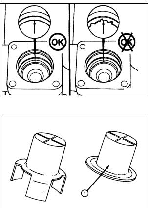
Some of the illustrations throughout this manual are generic and will not look exactly like the engine or parts used in your application. The illustrations can contain symbols to indicate an action required and an acceptable or not acceptable condition.
The illustrations are intended to show repair or replacement procedures. The procedure will be the same for all applications, although the illustration can differ.
th8sesa
Ca8vagc
Diesel Engine |
6 |
Introduction |
, D30S-3(B3.3), D25S-3(B3.3) user guide")
Engine Identification
Engine Dataplate
The engine dataplate shows specific information about the engine. The engine serial number (ESN) and control parts list (CPL) provide information for ordering parts and for service needs.
NOTE: The engine dataplate must not be changed unless approved by Cummins Engine Company, Inc.
00900248
00900249
Diesel Engine |
7 |
Engine Identification |
Specifications
Performance |
|
|
D20/25/30/32/33S-3 |
450/450Plus,460/460Plus |
|
|
Standard |
- |
SAEJ1995 |
||
Test Condition |
Air Cleaner |
- |
without but with 3.0kPa intake restriction |
||
Muffler |
- |
without but with 10.0kPa exhaust restriction |
|||
|
Alternator |
- |
without |
||
|
Fan |
- |
without |
||
Rated Power |
|
kW(PS) |
43.4 (59) @ 2200 rpm |
48.5 (65) @ 2600 rpm |
|
Max Torque |
|
Nm(kgf-m) |
202 (20.6) @ 1600 rpm |
214 (21.8) @ 1600 rpm |
|
Torque Rising |
|
|
7.4%for2200rpmrating |
20.0%for2600rpmrating |
|
BSFC |
@Rated Power |
g/kWh |
227 @2200rpm |
236 @ 2600rpm |
|
@Max Torque |
g/kWh |
219 @1600rpm |
226 @ 1600rpm |
||
|
|||||
General Engine Data |
|
|
Naturally Aspirated |
||
Engine Weight (Dry) Less Flywheel and Electronics |
245 kg [540 lb] |
||||
Compression Ratio |
|
|
|
18.8 |
|
Bore |
|
|
95 mm [3.74 in] |
||
Stroke |
|
|
115 mm [4.528 in] |
||
Displacement |
|
|
3.26 liters [199 in³] |
||
Firing Order |
|
|
|
1-2-4-3 |
|
Valve Clearance: |
|
Intake |
0.35 mm [0.014 in] |
||
|
Exhaust |
0.50 mm [0.020 in] |
|||
|
|
||||
Rotation Viewed from the Front of the Engine |
Clockwise |
||||
|
|
|
|
||
Lubrication System |
|
|
Naturally Aspirated |
||
Regulating Valve Opening Pressure |
|
490 kPa [71 psi] |
|||
Lubricating Oil Capacity: |
Total System |
7.5 liters [8.0 qt] |
8.0 liters [8.5 qt] |
||
Standard Oil Pan Only |
7.0 liters [7.4 qt] |
||||
|
|
||||
Lubricating Oil Pressure at Idle (Minimum Allowable) |
69 kPa [10 psi] |
||||
Lubricating Oil Pressure at Rated (Minimum Allowable) |
245 kPa [35 psi] |
||||
Oil Filter Differential Pressure to Open Bypass Valve |
98 kPa [14 psi] |
||||
Number of liters [qt] from Low to High |
1.5 liters [1.6 qt] |
||||
|
|
|
|
||
Cooling System |
|
|
Naturally Aspirated |
||
Coolant Capacity (Engine Only ) |
|
4.5 liters [4.75 qt] |
|||
Standard Modulating |
Thermostat Start |
82° C [180° F] |
|||
Range: |
|
Fully Open |
95° C [203° F] |
||
Maximum Pressure Cap @ Sea Level |
50 kPa [7 psi] |
||||
|
|
|
|
||
Air Induction System |
|
|
Naturally Aspirated |
||
Maximum Allowable Intake Restriction at Rated Speed and |
762 mm H2O |
||||
Load with Dirty Filter Element |
|
[30 in H2O] |
|||
|
|
|
|
||
Exhaust System |
|
|
Naturally Aspirated |
||
Maximum Allowable Exhaust Restriction at Rated Speed and |
75 mm Hg |
||||
Load with Dirty Filter Element |
|
|
[3 in Hg] |
||
|
|
|
|
||
Fuel System |
|
|
Naturally Aspirated |
||
Maximum Allowable Restriction to the Fuel Transfer Pump |
75 mm Hg |
||||
or Filter Head Must Not Exceed |
|
|
[3 in Hg] |
||
Maximum Allowable Return Line Restriction Must Not |
190.5 mm Hg |
||||
Exceed |
|
|
[7.5 in Hg] |
||
Inlet Pressure to the Injection Pump Range |
0.00 kPa [0.00 psi] to 39.0 kPa [5.00 psi] |
||||
|
|
|
|
||
Electrical System |
|
|
Naturally Aspirated |
||
Minimum Recommended Battery |
12-VDC Starter |
|
550 CCA |
||
Capacity with Light Accessories*: |
|
||||
|
|
|
|||
Minimum Recommended Battery |
12-VDC Starter |
|
730 CCA |
||
Capacity with Heavy |
|
|
|||
Accessories**: |
|
|
|
|
|
Maximum Allowable |
Resistance |
12-VDC Starter |
0.0012 ohms |
||
of the Starting Circuit: |
|
||||
|
|
|
|
||
*Typical light accessories include: Alternator, small steering pump, and disengaged clutch. |
|||||
**Typical heavy accessories include: Hydraulic pump and torque converter. |
|
||||
Diesel Engine |
8 |
Engine Identification |
Engine Diagrams
Engine Views
The following illustrations show the locations of the major external engine components, filters, and other service and maintenance points. Some external components will be at different locations for different engine models.
Intake Side
(Naturally Aspirated)
00900138
1. |
Intake Manifold |
5. |
Fan |
2. |
Starting Motor |
6. |
Fuel Filter |
3. |
Fuel Injection Pump |
7. |
Oil Fill Cap. |
4. |
Crankshaft Pulley |
|
|
Diesel Engine |
9 |
Engine Identification |
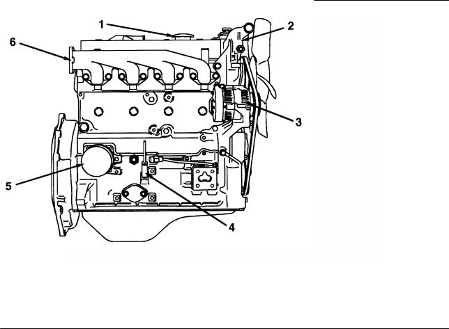
Exhaust Side
(Naturally Aspirated)
00900139
1. |
Oil Fill Cap |
4. |
Dipstick |
2. |
Thermostat Housing |
5. |
Oil Filter |
3. |
Alternator |
6. |
Exhaust Manifold. |
Diesel Engine |
10 |
Engine Identification |
Front View
(Naturally Aspirated)
00900140
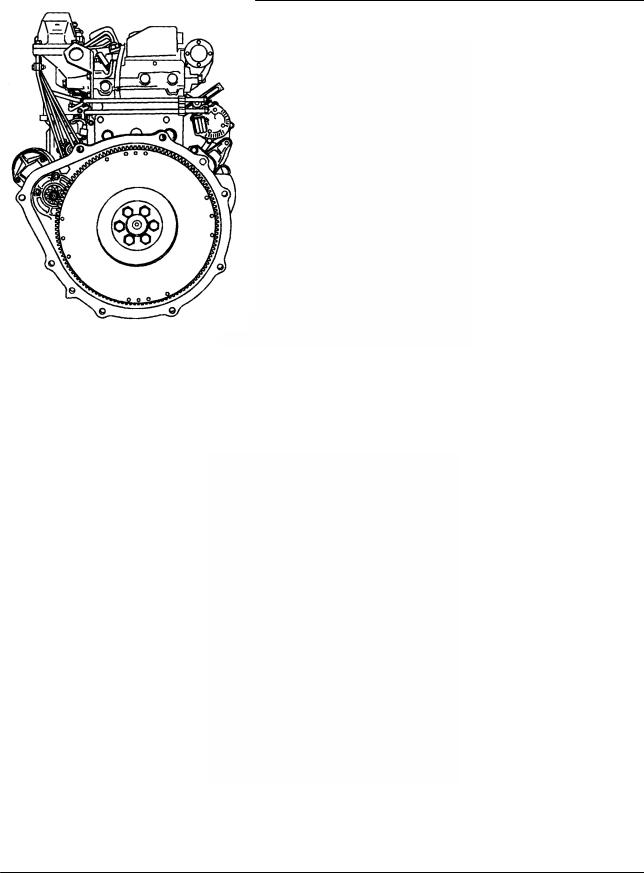
Rear View
(Naturally Aspirated)
00900141
Diesel Engine |
11 |
Engine Identification |
Exhaust Side
(Naturally Aspirated)
00900146
1. |
Oil Strainer |
8. |
Camshaft |
2. |
Oil Pump |
9. |
Piston |
3. |
Oil Cooler (Optional) |
10.Intake and Exhaust Valve |
|
4. |
Regulator Valve |
11.Rocker Arm |
|
5. |
Oil Filter |
12.Timing Gear |
|
6. |
Safety Valve |
13.Cooling Water. |
|
7. |
Crankshaft |
|
|
Diesel Engine |
12 |
Engine Identification |
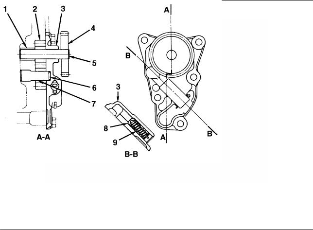
Oil Pump
00900148
1. |
Bushing |
8. |
Regulator Valve |
2. |
Gear Drive (number of teeth: 7) |
9. |
Valve Spring. |
3. |
Pump cover |
Oil pump |
|
4. |
Oil Pump Drive Gear (number of teeth: 22) |
||
5. |
Driveshaft |
|
• Type: Gear Type |
6. |
Drivenshaft |
|
• Pump Speed: Engine Speed x 1.182. |
7. |
Driven Gear (number of teeth: 7) |
Regulator Valve |
|
|
|
||
• Set Pressure: 490 ± 50kPa [71 ± 7psi].
Diesel Engine |
13 |
Engine Identification |
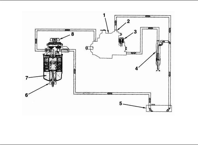
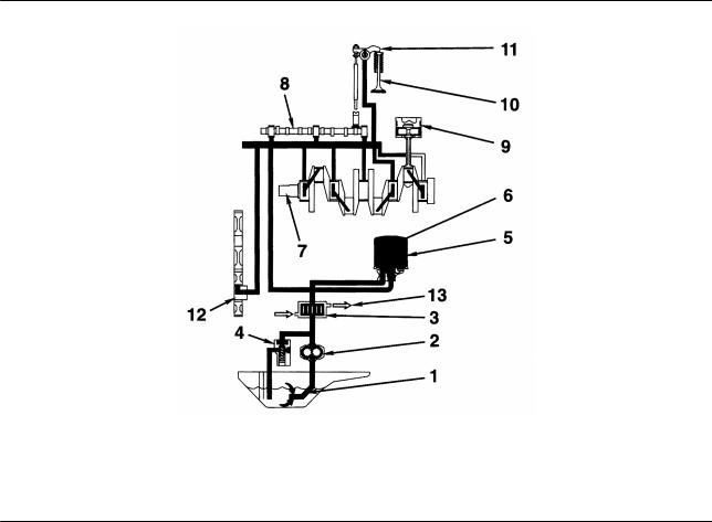
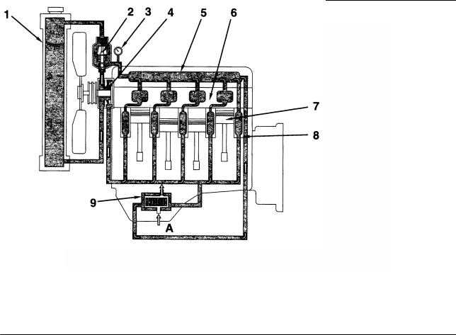
Fuel System
00900149
1. |
Fuel Injection Pump |
5. |
Fuel Tank |
2. |
Overflow Valve |
6. |
Water-in-Fuel Sensor (WIF) |
3. |
Fuel Solenoid |
7. |
Fuel Filter |
4. |
Fuel Injection Nozzle |
8. |
Hand Priming Pump. |
Diesel Engine |
14 |
Engine Identification |
|
|
|
|
|
|
|
|
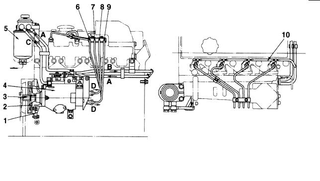
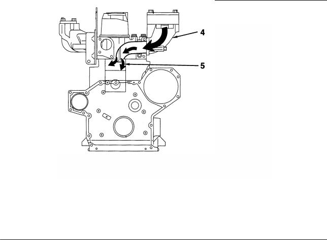
Fuel Injection Pump |
|
|
|
|
00900150 |
|
|
|
|
|
|
1. |
Pump Holder |
A. Fuel Inlet (from Fuel Tank) |
||
2. |
Fuel Injection Pump Drive Gear |
B. To. Fuel Tank |
||
|
|
(number of teeth: 52) |
C. To Fuel Injection Pump |
|
3. |
Drive Shaft |
D. To Fuel Injection Nozzle. |
||
4. |
Fuel Injection Pump (Body) |
Fuel Injection Pump |
||
5. |
Fuel Filter |
|||
6. |
Fuel Injection Pipe (No. 1) |
• Maker: Zexel |
||
7. |
Fuel Injection Pipe (No. 2) |
• Type: VE |
||
8. |
Fuel Injection Pipe (No. 3) |
• Lubrication Method: Forced Lubrication with Fuel |
||
9. |
Fuel Injection Pipe (No. 4) |
Governor |
||
|
10.Spill Tube |
|||
|
|
|
• Type: Mechanical, All-speed Type. |
|
Diesel Engine |
15 |
Engine Identification |
|
|
|
|
|
|
|
|
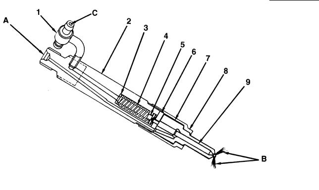
Fuel Injection Nozzle |
|
|
|
|
00900151 |
|
|
|
|
|
|
1. |
Fuel Drain Line Connector |
A. Fuel Inlet (from injection pump) |
||
2. |
Nozzle Holder |
B. Fuel Injection (to cylinder) |
||
3. |
Adjusting Shim |
C. Fuel Return (to fuel tank). |
||
4. |
Nozzle spring |
Fuel Injection Nozzle |
||
5. |
Spring seat |
|||
6. |
Intermadiate Plate |
• Maker: Zexel |
||
7. |
Nozzle Body |
• Injection Pressure: 40 MPa |
||
8. |
Retaining Nut |
• Adjustment of Injection Pressure: By Shim. |
||
9. |
Needle. |
|
|
|
Diesel Engine |
16 |
Engine Identification |
Cooling System
00900147
1. |
Radiator |
6. |
Cylinder Head |
2. |
Thermostat |
7. |
Piston |
3. |
Water Temperature Gauge |
8. |
Cylinder Block |
4. |
Water Pump |
9. |
Oil Cooler (optional). |
5. |
Water Manifold |
A. From Oil Pump (oil). |
|
Diesel Engine |
17 |
Engine Identification |
Air Intake System
00900227
1.Filtered Air
2.Intake Manifold
3.Intake Valve Port.
Diesel Engine |
18 |
Engine Identification |
Exhaust System
00900232
1.Exhaust Valve Port
2.Exhaust Manifold
Diesel Engine |
19 |
Engine Identification |
Procedures and Techniques
A thorough analysis of the customer's complaint is the key to successful troubleshooting. The more information known about a complaint, the faster and easier the problem can be solved.
The Troubleshooting Symptom Charts are organized so that a problem can be located and corrected by doing the easiest and most logical things first. Complete all steps in the sequence shown from top to bottom.
It is not possible to include all the solutions to problems that can occur; however, these charts are designed to stimulate a thought process that will lead to the cause and correction of the problem.
Follow these basic troubleshooting steps:
•Get all the facts concerning the complaint
•Analyze the problem thoroughly
•Relate the symptoms to the basic engine systems and components
•Consider any recent maintenance or repair action that can relate to the complaint
•Double-check before beginning any disassembly
•Solve the problem by using the symptom charts and doing the easiest things first
•Determine the cause of the problem and make a thorough repair
•After repairs have been made, operate the engine to make sure the cause of the complaint has been corrected
Troubleshooting Symptoms Charts
Use the charts on the following pages of this section to aid in diagnosing specific engine symptoms. Read each row of blocks from top to bottom. Follow through the chart to identify the corrective action.
Diesel Engine |
20 |
Troubleshooting Symptoms |
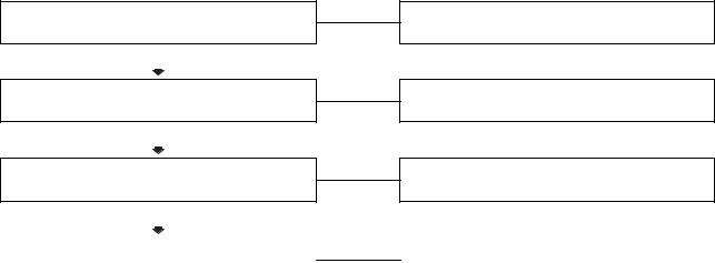
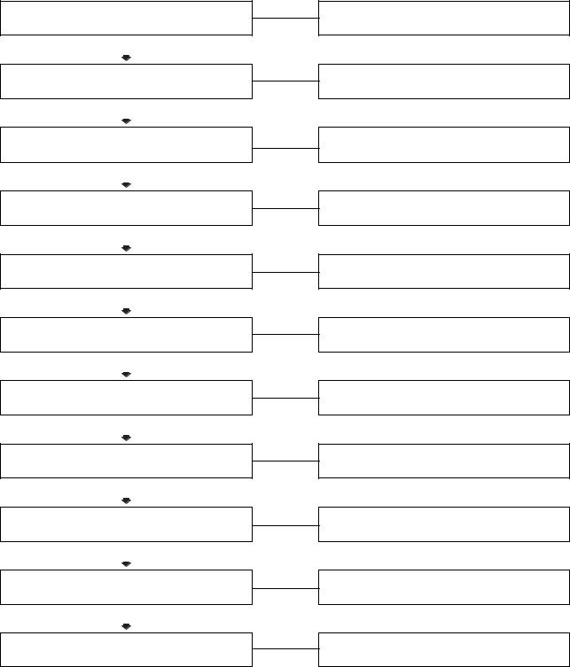
Engine Will Not Crank or Cranks Slowly
This is symptom tree T-002.
Cause |
Correction |
Defective wiring of starting circuit
OK
Specific gravity of battery electrolytr is low, or Battery voltage is low
OK
Staring motor is malfunctioning
OK
Troubleshoot and repair starting circuit wiring including relays and switches.
Check the alternator. If the alternator checks Out, replace the battery.
Replace the staring motor.
Ring gear tooth surface is chipped or damaged |
|
Replace ring gear. |
|
|
|
Diesel Engine |
21 |
Troubleshooting Symptoms |
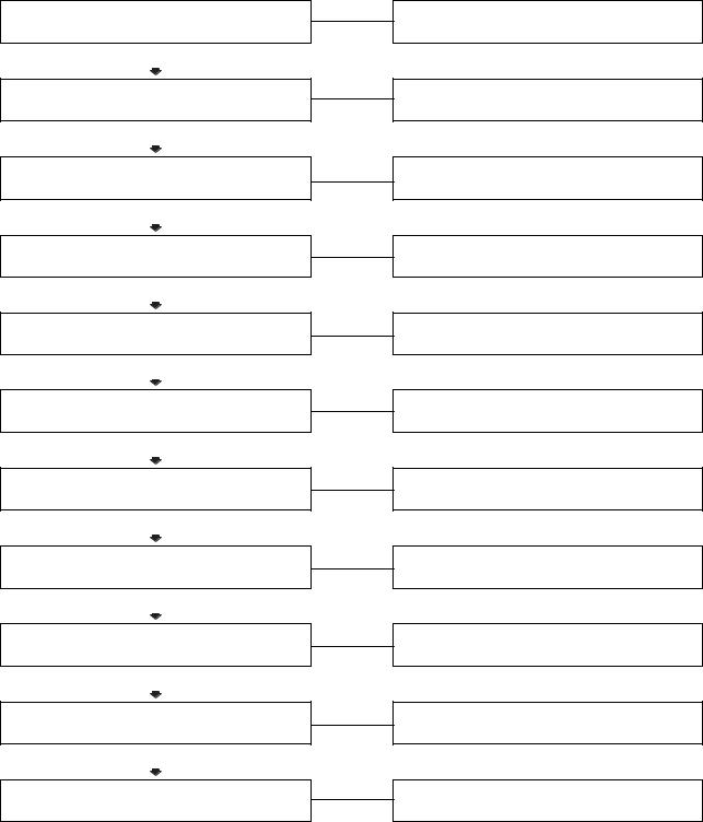
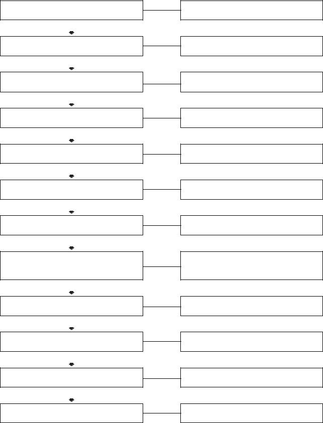
Engine Cranks But Will Not Start (No Exhaust Smoke)
This is symptom tree T-003.
Cause
Fuel level low in the tank
OK
Improper fuel is being used
OK
Clogged fuel tank air breather hole
OK
Engine does start when voltage is applied to the fuel cut solenoid valve
OK
Engine does not start when voltage is applied to the fuel cut solenoid valve
OK
Clogged prefilter
OK
Clogged fuel filter or strainer
OK
Clogged or leaking fuel piping
OK
Feed pump is damaged or seized
OK
Injector are plugged
OK
Injection pump driveshaft or driveshaft key is damaged
Correction
Fill the supply tank.
Drain fuel and replace with correct fuel.
Clean the fuel tank breather.
Troubleshoot and repair the circuit wiring.
Replace the fuel cut solenoid valve.
Clean the prefilter.
Clean or replace the fuel filter or strainer.
Clean and repair the fuel piping.
Replace the feed pump.
Replace the injectors.
Repair or replace the injection pump.
Diesel Engine |
22 |
Troubleshooting Symptoms |

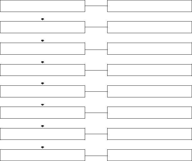
Engine Difficult to Start or Will Not Start (Exhaust Smoke)
This is symptom tree T-004.
Cause
Starting aid malfunctioning or heater mount Does not become warm
OK
Crank speed is too slow (minimum crank Speed: 150 rpm)
OK
Improper fuel is being used
OK
Clogged air cleaner element
OK
Clogged prefilter
OK
Clogged fuel filter or strainer
OK
Leakage, clogging, air in fuel system
OK
Injection pump timing is incorrect
OK
(Continued)
Correction
Replace the starting aid.
Verify drive units are not engaged. Check the Battery and recharge or replace.
Drain fuel and replace with correct fuel.
Clean or replace the air cleaner element.
Clean the prefilter.
Clean or replace the fuel filter or strainer.
Repair and clean the fuel filter or strainer.
Retime the injection pump.
Diesel Engine |
23 |
Troubleshooting Symptoms |

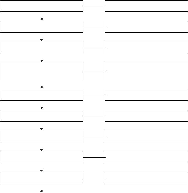
Engine Difficult to Start or Will Not Start (Exhaust Smoke) (Continued)
Cause
Overhead adjustments are not correct
OK
Overhead components are damaged
OK
Defective or clogged injection nozzle
OK
Injection pump is malfunctioning
OK
Worn piston ring or cylinder resulting in low compression
Correction
Measure and adjust the overhead settings.
Inspect the rocker levers, rocker shafs, and valve for excessive damage. Replace as necessary.
Replace the defective or clogged injection nozzle
Repair or replace the injection pump.
Replace the worn piston ring or cylinder.
Diesel Engine |
24 |
Troubleshooting Symptoms |
Engine Has Poor Respones
This is symptom tree T-005.
Cause
Clogged air cleaner element
OK
Clogged fuel tank air breather hole
OK
Clogged prefilter
OK
Clogged fuel filter or strainer
OK
Clogged or leaking fuel piping
OK
Overhead adjustments are not correct
OK
Defective contact of valve or valve seat Resulting in low compression
OK
Turbocharger does not rotate freely
OK
Defective or clogged injection nozzle
OK
Injection pump is malfunctioning
OK
Worn piston ring or cylinder resulting in low Compression
Correction
Clean or replace the air cleaner element
Clean the fuel tank breather.
Clean or replace the fuel filter or strainer.
Clean and repair the fuel piping
Clean and adjust the overhead settings.
Measure and adjust the overhead settings.
Replace the cylinder head.
Replace the turbocharger.
Replace the defective or clogged injection nozzle.
Repair or replace the injection pump.
Replace the worn piston ring or cylinder.
Diesel Engine |
25 |
Troubleshooting Symptoms |
Engine Stops During Operation
This is symptom tree T-006.
Cause
Chassis powertrain is damaged or overloaded
OK
Fuel level low in the tank
OK
Clogged fuel tank air breather hole
OK
Clogged prefilter
OK
Clogged fuel filter or strainer
OK
Clogged or leaking fuel piping
OK
Feed pump piston is damaged or seized
OK
Overhead components are damaged
OK
Injection pump is malfunctioning
OK
Gear train damaged or seized
OK
Piston or connecting rod is damaged
OK
Crankshaft bearing is damaged
Correction
Refer to the OEM’s service manuals.
Fill the supply tank.
Clean the fuel tank breather.
Clean the prefilter.
Clean and or replace the fuel filter or strainer.
Clean and repair the fuel piping.
Replace the feed pump.
Inspect the rocker levers, rocker shafts, and valves for excessive damage. Replace as necessary.
Replace the injection pump.
Refer to OEM’s service manuals.
Replace damaged piston or connecting rod.
Replace damaged crankshaft bearing.
Diesel Engine |
26 |
Troubleshooting Symptoms |
Engine Runs Rough or Misfires
This is symptom tree T-007.
Cause
Fuel level low in the tank
OK
Clogged fuel tank air breather hole
OK
Low idle speed is adjusted too low
OK
Clogged prefilter
OK
Clogged fuel filter or strainer
OK
Line between the fuel tank and feed pump are clogged or have air in them
OK
Line between the feed pump and the injector nozzle are clogged or have air in them
OK
Injection pump is malfunctioning
Correction
Fill the supply tank.
Clean the fuel tank breather.
Adjust the low idle speed.
Clean the prefilter.
Clean or replace the fuel filter or strainer.
Clean and repair the lines.
Clean and repair the lines.
Replace the injection pump.
Diesel Engine |
27 |
Troubleshooting Symptoms |
Engine Power Output Low
This is symptom tree T-008.
Cause
Improper fuel is being used
OK
Clogged air cleaner element
OK
Clogged fuel tank air breather hole
OK
Full throttle can not be achieved because the fuel lever linkage is bent or not adjusted correctly
OK
Clogged prefilter
OK
Clogged fuel filter or strainer
OK
Clogged or leaking fuel piping
OK
Feed pump is defective
OK
Overhead adjustments are not correct
OK
(Continued)
Correction
Drain and replace the fuel with the correct fuel.
Clean or replace the air cleaner element.
Clean the fuel tank breather.
Repair or adjust the fuel lever linkage.
Clean the prefilter.
Clean and or replace the fuel filter or strainer.
Clean and repair the fuel piping.
Replace the feed pump.
Measure and adjust the overhead settings.
Diesel Engine |
28 |
Troubleshooting Symptoms |
 Loading...