


CN-220B
Daewoo CN-220B, DTQ - 20D4SSF, DTQ - 20D4AS, DTQ - 20D5FC, DTQ - 20D5FS Service Manual
...
Service Manual
Color Television
CHASSIS : CN-220B/C
Model : DTQ - 20D5FS / FSP
DTQ - 20D5FC
S/M No. : CN220NTEF0R1
OCT. 2001
DAEWOO ELECTRONICS CO., LTD
http : //svc.dwe.co.kr
MODEL
ITEM
DTQ-20D5FS DTQ-20D5FSP 20D5FC
TV STANDARD NTSC-M
POWER INPUT 120V 60HZ 220V 60HZ
POWER CONSUMPTION 84W
TUNING SYSTEM Frequency Synthesizer (FS) Tuning System
TUNING RANGES
VHF : 2 ~ 13 (12)
UHF : 14 ~ 69 (56)
A~W, A- 5 ~ A-1, W + 1 ~ W + 84
SOUND OUTPUT 5W + 5W
SPEAKER 8 ohm 5W x 2EA
ANTENNA INPUT
IMPEDANCE
75 ohm Unbalanced
AUXILIARY INPUT
TERMINAL
Front : Video, Audio, Earphone
Rear: Video, Audio, (R,L)
INTERMEDIATE
FREQUENCIES
Picture IF Carrier Frequency : 45.75 MHZ
Sound IF Carrier Frequency : 41.25 MHZ
Color Sub-Carrer Frequency : 3.579545 MHZ
REMOTE CONTROL R - 40
SPECIAL FUNCTIONS
AV only PIP
ICON MENU TYPE
STEREO / SAP
3 - Language OSD
with Caption
SPECIFICATIONS
120V 60HZ
DTQ - 20D4AS / ASP
DTQ - 20D4SSF / SSSP
✔ Caution:In this Service Manual, some parts can be changed for improving, their performance
without notice in the parts list.So,if you need the latest parts information, please refer
to PPL(Parts Price List) in Service information Center(http://svc.dwe.co.kr)

1
TABLE OF CONTENTS
SAFETY INSTRUCTION .................................................................................................................. 2
SPECIFICATIONS ............................................................................................................................ 3
CIRCUIT BLOCK DIAGRAM ........................................................................................................... 5
ALIGNMENT INSTRUCTION ........................................................................................................... 6
Your Remote Control ........................................................................................................................ 6
Service Mode Adjustment ................................................................................................................. 7
Assembly Adjustment ....................................................................................................................... 8
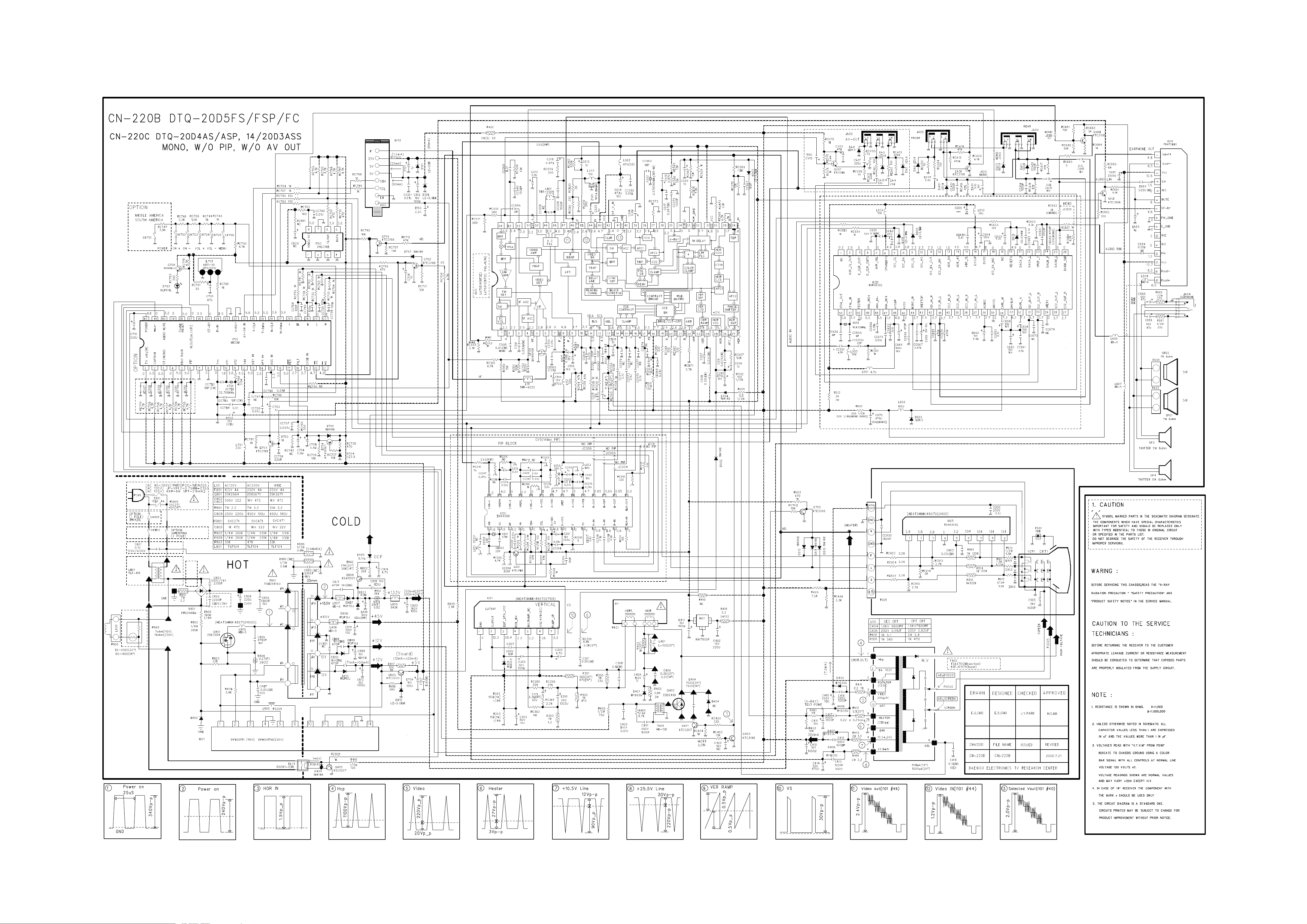
SCHEMATIC DIAGRAM .................................................................................................................. 12
EXPLODED VIEW ............................................................................................................................ 12
PRINTED CIRCUIT BOARD ............................................................................................................ 13
SERVICE PARTS LIST .................................................................................................................... 14
The Different Parts List ..................................................................................................................... 21
APPENDIX (“ Appendix is provided only by internet [http://svc.dwe.co.kr] ”)
IC DESCRIPTION ........................................................................................................................... 1
Trouble Shooting Guide ............................................................................................................... 11
1. No Power .................................................................................................................................... 11
2. No Picture ................................................................................................................................... 12
3. No Sound .................................................................................................................................... 13
4. CH Don’t Stop ............................................................................................................................. 14
5. No Color ..................................................................................................................................... 15
6. No Vertical Deflection ................................................................................................................. 15
7. No On-Screen Display ................................................................................................................ 16
8. Remote Control Does not Operate ............................................................................................. 16

2
SAFETY INSTRUCTION
WARNING :
Only competent service personnel may carry out work involving the testing or repair of this equipment
1. Excessive high voltage can produce potentially hazardous X-RAY RADIATION. To avoid such hazards, the high
voltage must not exceed the specified limit. The nominal value of the high voltage of this receiver is 22-23 kV (14”) or
24-26 kV (20” - 21”) at max beam current. The high voltage must not, under any circumstances, exceed 27.5 kV (14”,
20”), 29KV (21”). Each time a receiver requires servicing, the high voltage should be checked. It is important to use an
accurate and reliable high voltage meter.
2. The only source of X-RAY Radiation in this TV receiver is the picture tube. For continued X-RAY RADIATION
protection, the replacement tube must be exactly the same type tube as specified in the parts list.
X-RAY RADIATION PRECAUTION
1. Potentials of high voltage are present when this receiver is operating. Operation of the receiver outside the cabinet or
with the back cover removed involves a shock hazard from the receiver.
1)Servicing should not be attempted by anyone who is not thoroughly familiar with the precautions necessary when
working on high voltage equipment.
2)Discharge the high potential of the picture tube before handling the tube. The picture tube is highly evacuated and if
broken, glass fragments will be violently expelled.
2. If any Fuse in this TV receiver is blown, replace it with the FUSE specified in the Replacement Parts List.
3. When replacing a high wattage resistor (oxide metal film resistor) in circuit board, keep the resistor body 10 mm away
from the circuit board.
4. Keep wires away from high voltage or high temperature components.
5. This receiver must operate under AC 230 volts, 5O Hz. NEVER connect to a DC supply of any other voltage or
frequency.
SAFETY PRECAUTION
Many electrical and mechanical parts in this equipment have special safety-related characteristics. These characteristics are
often passed unnoticed by a visual inspection and the X-RAY RADIATION protection afforded by them cannot necessarily be
obtained by using replacement components rated for higher voltage, wattage, etc. Replacement parts which have these spe-
cial safety characteristics are identified in this manual and its supplements, electrical components having such features are
identified by designated symbol on the parts list. Before replacing any of these components, read the parts list in this manual
carefully. The use of substitutes replacement parts which do not have the same safety characteristics as specified in the parts
list may create X-RAY Radiation.
PRODUCT SAFETY NOTICE
3
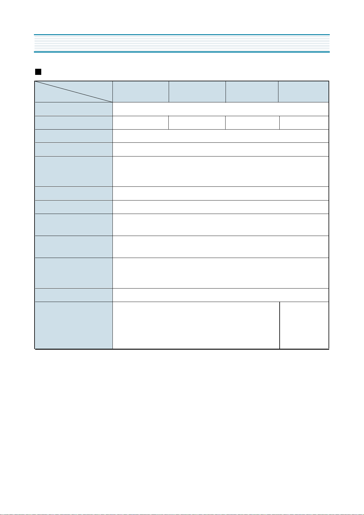
SPECIFICATIONS
CN-220B Chassis
MODEL
ITEM
DTQ-20D5FS
DTQ-20D5FSP
DTQ-20D4SSSP
TV STANDARD NTSC-M
POWER INPUT 120V 60HZ 220V 60HZ 120V 60HZ 220V 60HZ
POWER CONSUMPTION 84W
TUNING SYSTEM Frequency Synthesizer (FS) Tuning System
TUNING RANGES
VHF : 2 ~ 13 (12)
UHF : 14 ~ 69 (56)
A~W, A- 5 ~ A-1, W + 1 ~ W + 84
SOUND OUTPUT 5W + 5W
SPEAKER 8 ohm 5W x 2EA
ANTENNA INPUT IMPED-
ANCE
75 ohm Unbalanced
AUXILIARY INPUT TERMI-
NAL
Front : Video, Audio, Earphone
Rear: Video, Audio, (R,L)
INTERMEDIATE FREQUEN-
CIES
Picture IF Carrier Frequency : 45.75 MHZ
Sound IF Carrier Frequency : 41.25 MHZ
Color Sub-Carrer Frequency : 3.579545 MHZ
REMOTE CONTROL R - 40
SPECIAL FUNCTIONS
AV only PIP
ICON MENU TYPE
STEREO / SAP
3 -Language OSD
with Caption
DTQ-20D5FC
ICON MENU TYPE
STEREO / SAP
3 -Language OSD
with Caption
4
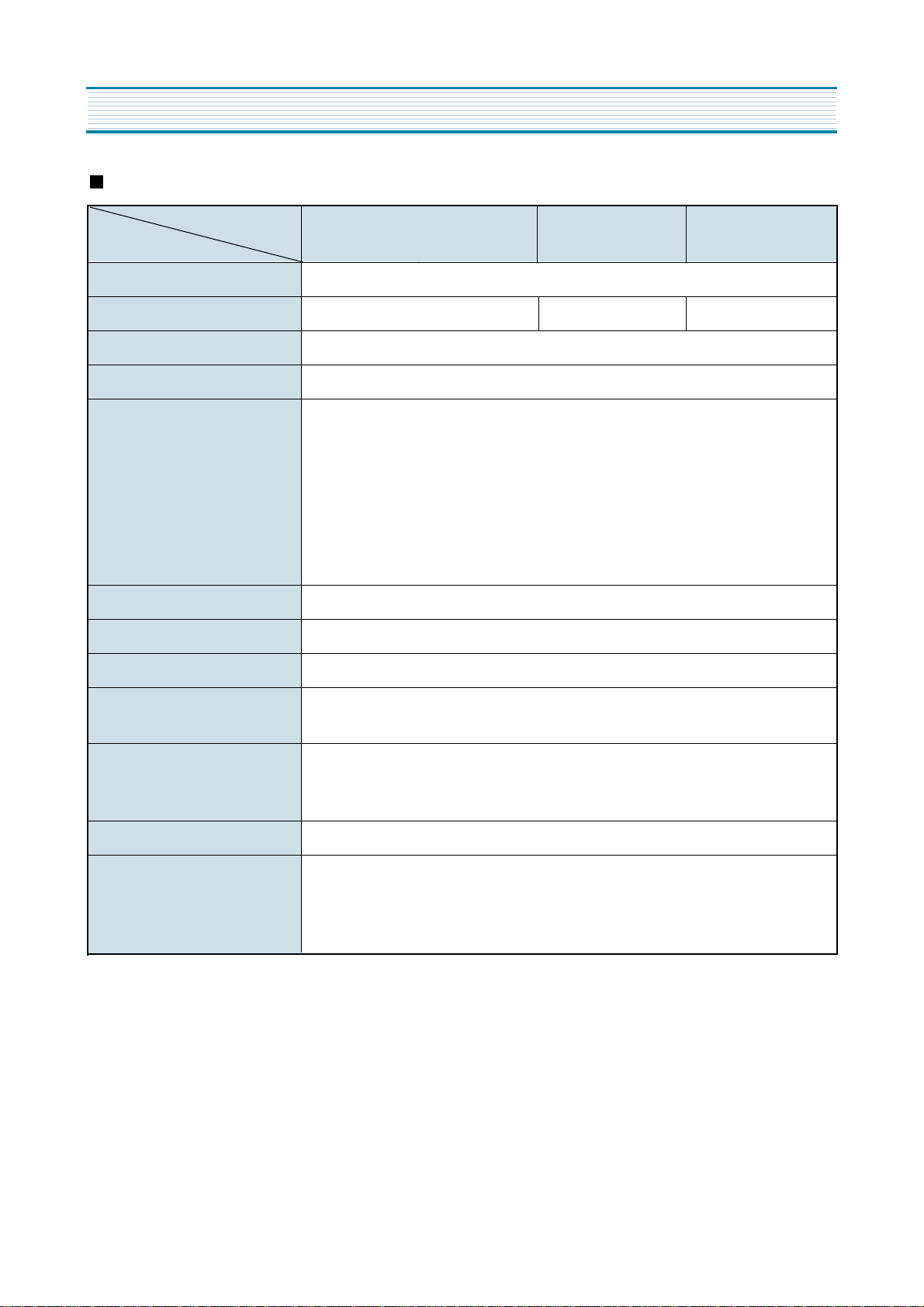
SPECIFICATIONS
CN-220C Chassis
MODEL
ITEM
DTQ-20D4AS
DTQ-20D4ASP
TV STANDARD
NTST-M
POWER INPUT
120V 60HZ
220V 60HZ
90-260V 60HZ
POWER CONSUMPTION
84W
TUNING SYSTEM
Frequency Synthesizer (FS) Tuning System
TUNING RANGES
TV VHF(L) : CH 2 ~ CH 6
UHF(H) : CH 7 ~ CH 13
UHF : CH 14 ~ CH 69
CATV VHF(L) : 5A, A, B, A-5 - A-1
CH 2 - CH 6
VHF(H) : C - W + 11
CH 7 - CH 13
UHF : W + 12 - W + 84
SOUND OUTPUT
5W + 5W
SPEAKER
8 ohm 5W x 2EA
ANTENNA INPUT IMPEDANCE
75 ohm Unbalanced
AUXILIARY INPUT TERMINAL
Front : Video, Audio, Earphone
Rear: Video, Audio, (R,L)
INTERMEDIATE FREQUEN-
CIES
Picture IF Carrier Frequency : 45.75 MHZ
Sound IF Carrier Frequency : 41.25 MHZ
Color Sub-Carrer Frequency : 3.579545 MHZ
REMOTE CONTROL
R - 40
SPECIAL FUNCTIONS
1) ICON MENU TYPE
2) 3-Language OSD
3) WITH CAPTION
4) CH LABEL
DTQ-20D4ASP
5
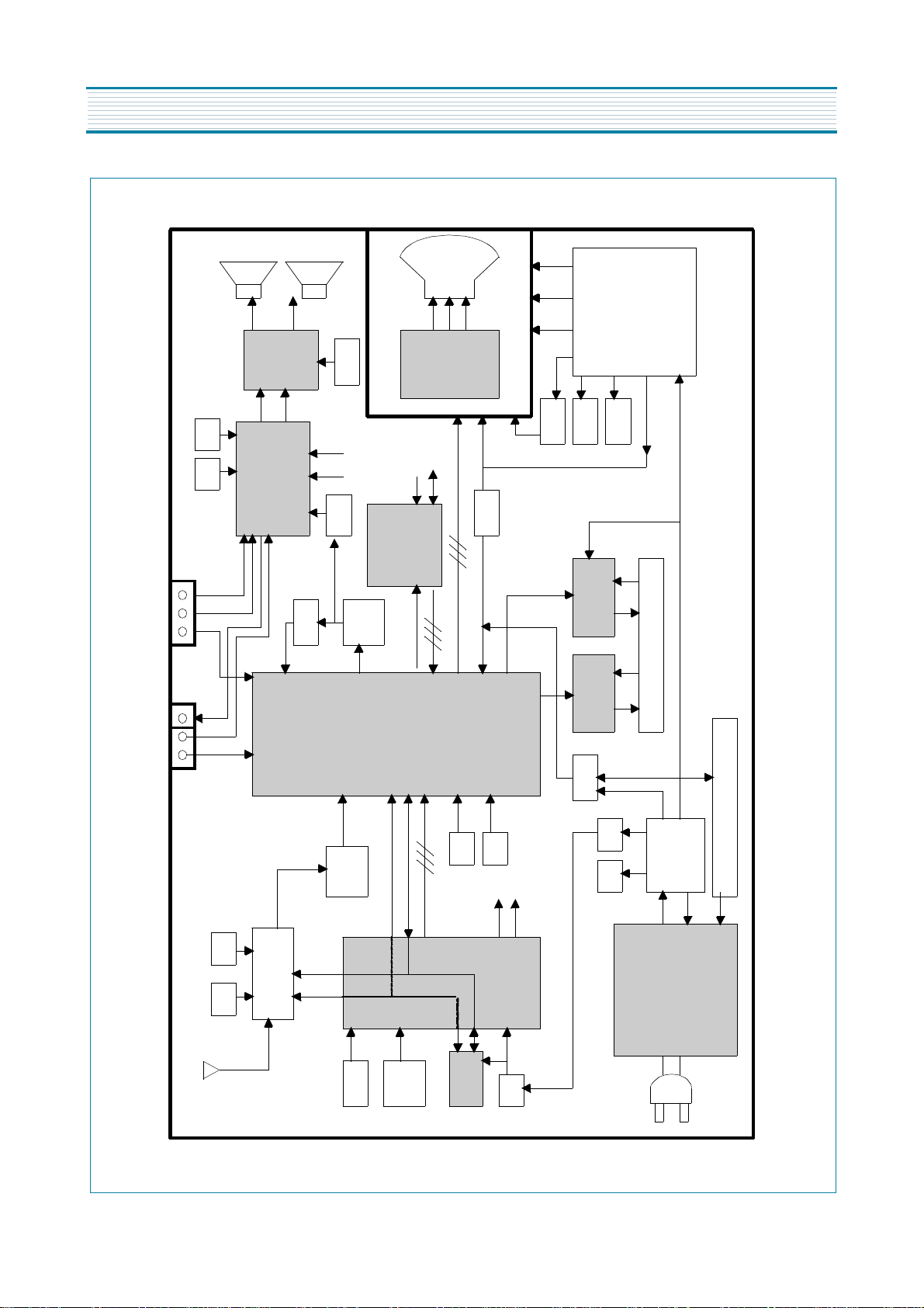
CIRCUIT BLOCK DIAGRAM
V
A H
V
L R
SCL SDA
(1)
(2)
OSD RGB
(1)
(2)
TUNER
DT5
-NF20F
u
-
COM IC
LC8632
40
SCL
SDA
SOUND
SCL
SOUND
SDA
MAIN
IC
DCT814B
SCL
SDA RGB
SOUND IC
MSP3430G
SCL SDA
Scre
en
Fouse H.
V
.
FBT
HEATER
POWER IC
2SK2564
EEPROM
IR
SW1 ~
SW5
SAW
FILTER
VIDEO
AMP
TDA
6
103Q
10V
28V
SOUND
AMP
TDA7266
IF DET.
OUT
TRAP
BPF
5V
9V
5V
X-RAY
SMPS TRANS
TSM-3541A5
DPM001T1(110V),
DP001T1A(
220V)
14V
5V
33V
VERTICAL
LA784
1
HOR. OUTPUT
2
SD2499
DEFLECTION YOKE
OCP
26V
14V
9V 5V
EARPHONE
A/V IN 2
RF
220
V
PIP
IC
SDA9388
CVS SCL
RGB SDA
A/V IN 1
6
ALIGNMENT INSTRUCTIONS
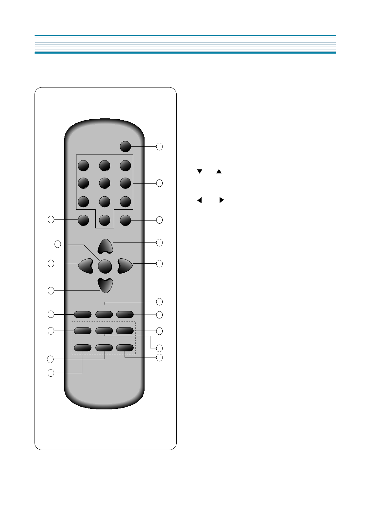
Your Remote Control
1. POWER
Use this button to turn your TV on or off.
2. 0 - 9
Use these buttons to change channels.
3. MUTE
Use to turn the TV’ s sound on and off.
4. DISPLAY
Use this buttons to display the channel
number and status.
5. CH
Use these buttons to change channels on your
TV, or select items in the menu system.
6. VOL
Use these buttons to change your TV’ s volume,
to activate selections in the menu system, or to
change audio and video settings.
7. TV/VIDEO
Use this button to select main picture source.
8. MTS
Use this button to select one mode of Mono,
Stereo or SAP.
9. PREVIOUS
Use this button to return previous channel you were
watching.
10. PIP
Use this button to turn PIP on/off.
11. STILL
Use this button to still PIP source.
12. SWAP
Use this button to exchange PIP source and main
source.
13. SCREEN
Use this button to change the size of the picture
(from normal 4:3 to WIDE, ZOOM, and the original
4:3 in turn).
14. POSITION
Use this button to change position of pip on your TV.
15. INPUT
Use this button to select PIP source (TV/VIDEO).
CH
TV/VIDEO PREVIOUS
STILLPIP
SCREEN
POSITION
MENU
MUTE
123
456
78
0
9
1
2
3
5
6
7
5
4
8
11
12
11
15
14
13
10
7
POWER
DISPLAY
VOL
VOL
CH
MTS
SWAP
INPUT
6
7
SERVICE MODE ADJUSTMENTS
Follow the steps below whenever service adjustment is required. See Table- A and Table- B to determine if
service adjustments are required.
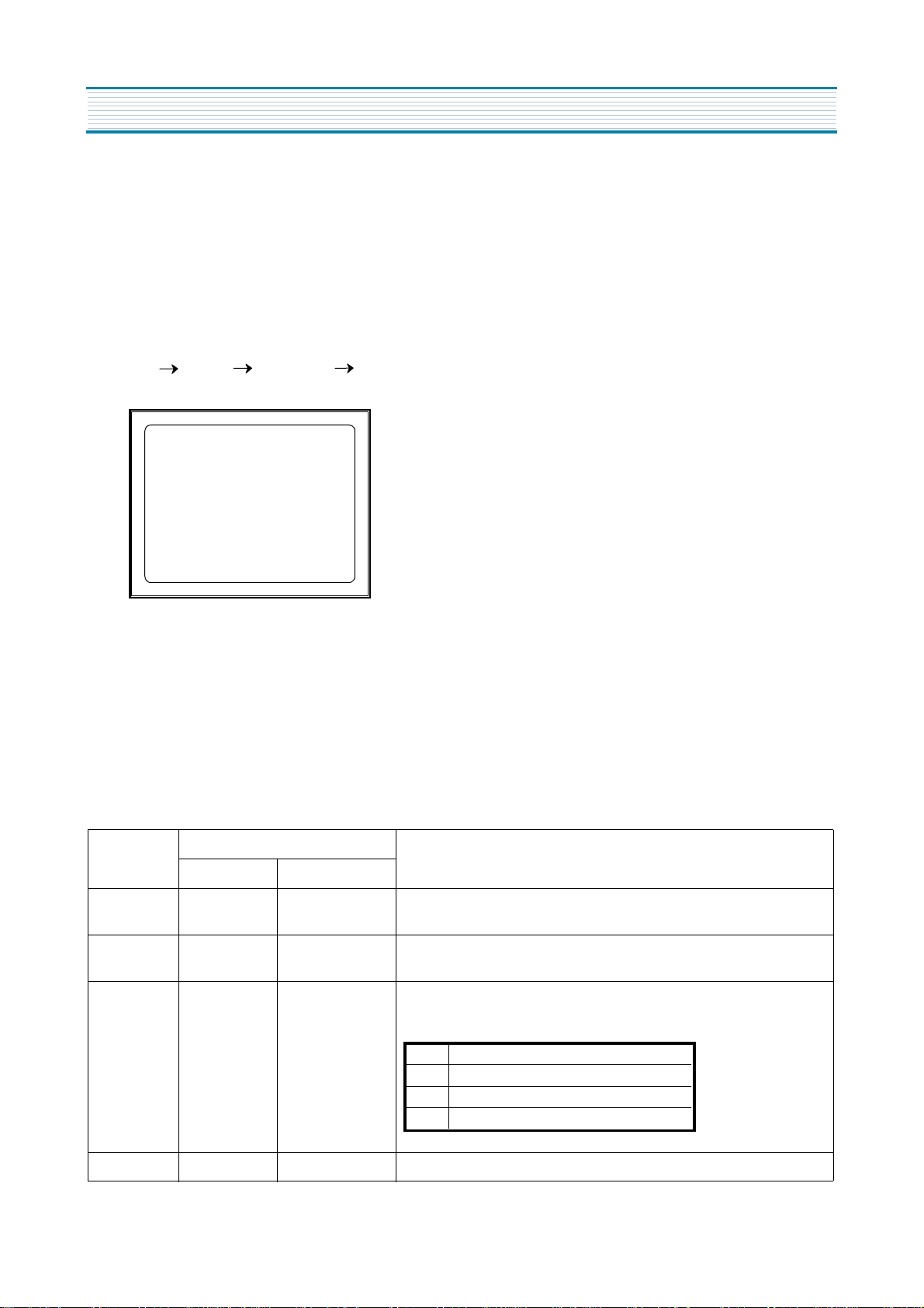
1) How to enter the service mode using the user remote control.
·
Turn the set on.
·
Direct the remote control to the reception window of TV.
·
Push buttons of remote control in sequence as follows.
1 MUTE DISPL
AY
MUTE
·
Then, the screen will appear as follows.
·
Using the channel up or channel down button, select the item you wish to adjust.
(The color of selected item turns into the red.)
·
Press the volume up or down button to enter in the service mode you wish to adjust.
2) How to memorize the adjusted values in the service mode.
·
Must press
DISPLAY
button the state which the screen is displaying each of service
menus
after all adjustments are completed each of all service menu.
Table-A : Adjust the values of service mode when a part is replaced.
PART
REPLACED
ADJUSTMENT
NOTES
NECESSARY UNNECESSARY
I701
(U-COM)
O
Data is stored in I703.
I101
(MAIN)
O
I703
(EEPROM)
O
Initial setting values are written from I701.
Adjusting Items
CRT O Adjust items related to picture tube only.(White Balance adjustment)
S2 SCRN
S5 IFC
S6 GEO
S8 W/B
S9 DP
S12 FACT
S7 PTRN NORMAL
S5 RFAGCD
S6 H.PHASE/V.POSI/V.SIZE
S8 RD/BD/RB/GB/BB
S9 Subbrightness
ALIGNMENT INSTRUCTIONS
8
ALIGNMENT INSTRUCTIONS
Table-B
*
indicates the items with different settings each of sets
ASSEMBLY ADJUSTMENTS
1) SCREEN ADJUSTMENT (S2)
·
Enter the service mode and select service adjustment S2.
·
You cna see the one horizontal line on the screen.
·
Adjust the Screen Control Volume (located on FBT) so that the horizontal line onscreen may be
disappeared.
·
Press the volume up or down button to exit in the screen adjustment mode.
MODE ADJUSTMENT ITEMS
DATA
REMARKS
INITIAL RANGE
S2 Screen Adjustment - -
S5
Auto RF AGC - -
Video Level (VIDEOL) 7 0 ~ 7 Must be set to 7
RF AGC Delay (RFAGCD) * 0 ~ 63 Align RF AGC threshold
FM Level (FM.LEV) 8 0 ~ 31 Must be set to 20
AGC Point 3.75 - Select AGC reference voltage
A/D VALUE - -
S6
Horizontal Phase(H.PHASE) * 0 ~ 31 Align sync to flyback pulse, using internal cross pattern(S7)
Vertical Position (V.POSI) * 0 ~ 63 Align vertical DC bias, using internal cross pattern(S7)
Vertical Size (V.SIZE) * 0 ~ 127 Align vertical amplitude, using internal cross pattern(S7)
NO SD POWER OFF YES - Automatically turn off in 15min for no received signal.
Vertical S-Correction (V SC) 0 0 ~ 31 Must be set to 6
Vertical Linearity (V LIN) 20 0 ~ 31 Must be set to 16
S7
Internal Black - - Display internal BLACK pattern
Internal 100% White - - Display internal 100% WHITE
Internal 60% White - - Display internal 60% WHITE
Internal Cross Pattern - - Display internal CROSS pattern
S8
Red Drive (RD) * 0 ~ 127 Align RED OUT AC level
Green Drive (GD) 10 0 ~ 15 Must be set to 10
Blue Drive (BD) * 0 ~ 127 Align BLUE OUT AC level
Red Bias (RB) * 0 ~ 255 Align RED OUT DC level
Green Bias (GB) * 0 ~ 255 Align GREEN OUT DC level
Blue Bias (BB) * 0 ~ 255 Align BLUE OUT DC level
S9
Subbrightness * 0 ~ 127 Align common RGB DC level
Contrast 10 0 ~ 27
Tint 27 0 ~ 27
Color 15 0 ~ 27
S12 Forwarding Mode - Factory Initialization
IN THE SCREEN ADJUSTMENT MODE, DONT PRESS OTHER BUTTONS EXCEPT VOLUME UP OR DOWN BUTTON.
NOTE

9
2) FOCUS ADJUSTMENT
·
Turn in a local station and adjust the Focus Control knob (located on FBT) for best picture
details at high light condition.
3) RF AGC DELAY ADJUSTMENT (S5)
·
Receive a good local channel.
·
Enter the service mode and select service adjustment S5.
·
You can see the OSD as shown in below.
·
Select RFAGCD item, press the volume up or down button until noise or beat in picture disappears.
·
Press the DISPLAY button to memorize the data.
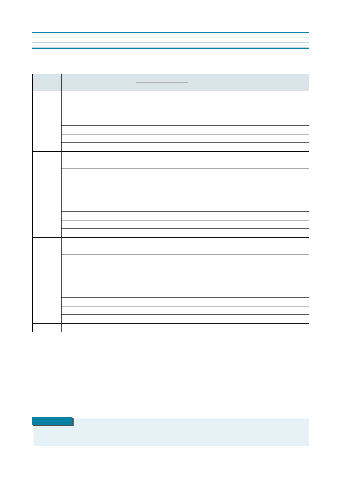
4) GEOMETRIC ADJUSTMENTS (S6)
·
Enter the service mode and select service adjustment S7.
·
Whenever you select the “ S7” using the volume up or down button, the screen is changing like this.
·
Using the volume up or down button, select internal cross pattern.
·
Select service adjustment S6
·
You can see the OSD as shown in below.
4-1. Horizontal Position Adjustment
·
Select H.PHASE item, adjust H.PHASE data value to obtain proper horizontal centering of the
internal cross pattern at the left and right of the screen.
4-2. Vertical Position Adjustment
·
Select V.POSI item, adjust V.POSI data value to center the raster properly on thescreen.
ALIGNMENT INSTRUCTIONS
IF CONTROL
AUTO RFAGC START
VIDEOL 7
RFAGCD 10
FM.LEV 8
AGC POINT 3.75
A/D VALUE : 8DH
MOVE ADJUST RECALL : SET
GEOMETRY
H. PHASE20
V. POSI 29
V. SIZE 70
NO SD POWER OFF YES
V SC 0
V LIN 20
MOVE ADJUST RECALL : SET
NORMAL BLACK WHITE100 WHITE60 CROSS
10
ALIGNMENT INSTRUCTIONS
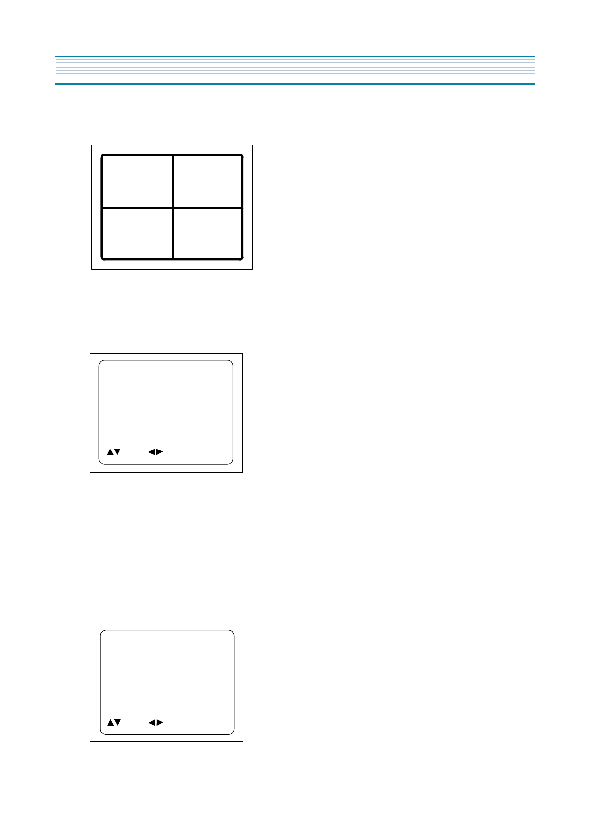
4-3. Vertical Size Adjustment
·
Select “ V.SIZE” item, adjust “ V.SIZE” data value to proper vertical size as follows.
5) WHITE BALANCE ADJUSTMENT(S8)
·
Receive a good local channel.
·
Enter the service mode and select service adjustment S8.
·
You can see the OSD as shown in below.
·
Using volume up or volume down, adjust service adjustment data of RD/GD/BD and RB/GB/BB until a good gray
scale with normal whites is obtained.ALIGNMENT INSTRUCTIONS
·
Press the DISPLAY button to memorize the data.
6) DIGITAL PRESET(D.P) ADJUSTMENTS(S9)
SUBBRIGHTNESS ADJUSTMENT
·
Receive a good local channel.
·
Enter the service mode and select service adjustment S9.
·
You can see the OSD as shoown in below.
RD 58
GD 10
BD 65
RB 105
GB 160
BB 100
MOVE ADJUST RECALL : SET
D.P.
SUB BRIGHTNESS 64
CONTRAST 10
TINT 27
COLOR 15
MOVE ADJUST RECALL : SET

11
ALIGNMENT INSTRUCTIONS
·
Select Subbrightness item, adjust Subbrightness data value
to obtain normal
brightness level.
·
Press the DISPLAY button to memorize the data.
CONTRAST
·
Fixed value = 10
TINT
·
Fixed value = 27
COLOR
·
Fixed value = 15
7) FACTORY OUTGOING MODE (S12 : FACT)
·
If you select the S12, then the set becomes factory outgoing status.
·
You can see the OSD “outgoing OK”
12
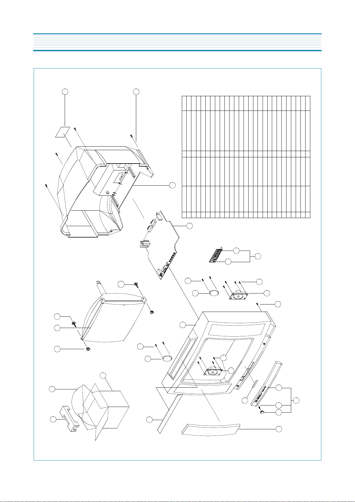
EXPLODED VIEW
20
19
EPS 20D51PAD
4858193401
LDPE T0.03X1300X1000
1
BAG PE
4858211800
DW-3
1
CARTON BOX
4858055200
150 ART P/E FILM(C/TV)1SPEC PLATE
4855415800
HIPS BK
4852155601
4856214902
30X190 BK2
SCREW CRT FIXING AS
30X80 BK
2SCREW CRT FIXING AS
4856013300
PVC T1.0
4857618000
TT2 WAS 3X12 MFZN BK
SCREW TAPPTIE
TT2 WAS 3X12 MFZN BK
2
SCREW TAPPTIE
7128301212
CUAU+ABS BK
1
MARK BRAND
4855617500
20
19
18
14-3
14-2
17
16
15
14
10-1
10
10-1
9-1
9-1
4-1
9
8
7
5
10
6
14-1
13
12
9
PC BK
1
4856013302
2
1
CR T2.0
4856215402
1
5 TT2 TRS 4X14 MFZN BK
7172401412
4
1
1
1
4945801+5541201
4851915401
HIPS BK
4854945801
1
1
11
1
1
2
8
7128301212
1
HIPS BK
4852073601
HIPS BK
4852326511
1
SWPA PIE 0.5
4856716000
ABS BK
2326511+4856401+6716000
PMMA MILKY
EGI T0.5
18
17
16-1
4855313101
4855541201
4852067101
4854856401
4852539601
16-1
16
15
14-3
14-2
14-1
14
13
12
11
10
9-1
9
8
7
6
5
4-1
4
3
2
1
COVER BACK
SCREW TAPPTITE
RUBBER
CRT
BUTTON CTRL
BUTTON
DECO SENSOR
INSU PLATE
SPEAKER
MASK FRONT
DECO COVER
PANEL FRONT
PANEL
SPRING
BUTTON POWER
GRILL
11
4
3
2
1
MATERI AL
REMARK S
MAIN PCB
PART N AME Q'tyPART C ODENo
13
A48JLL9 1x50 M16
DC-20SF
CN-220C
58G0000146
4856013302
PTMPMSJ801
PTSPPWJ776
1
DEGAUSIN G COIL
15
3
FELT T0.7 L=200CLOTH BL ACK
4857817611
12
2
9 8
SPEAKER
3
PC SMOG
1
1
EGI T0.5
GRILL R
4852539800
EGI T0.5
GRILL L
48525397 00
1
1
1
4
ABS BK
SWRM
4
4
SPECIAL SCREW
4856016100
1
1
30X190 BK
4856013302
150ART P/E FILM
4855415 800
4
1
4
CR T2.0
48562149 02
1
1
1
11
1
1
T2S TRS 4X14 MFZN
67122401 411
8
T2S TRS 3X12 MFZN
7128301211
A1050P- H24 T2.0
4855615900
1
SWPA PIE 0.5
48567160 00
ABS BK
HIPS BK
HIPS BK
4854945901
4852156201
4852067101
4854856601
48523266 01
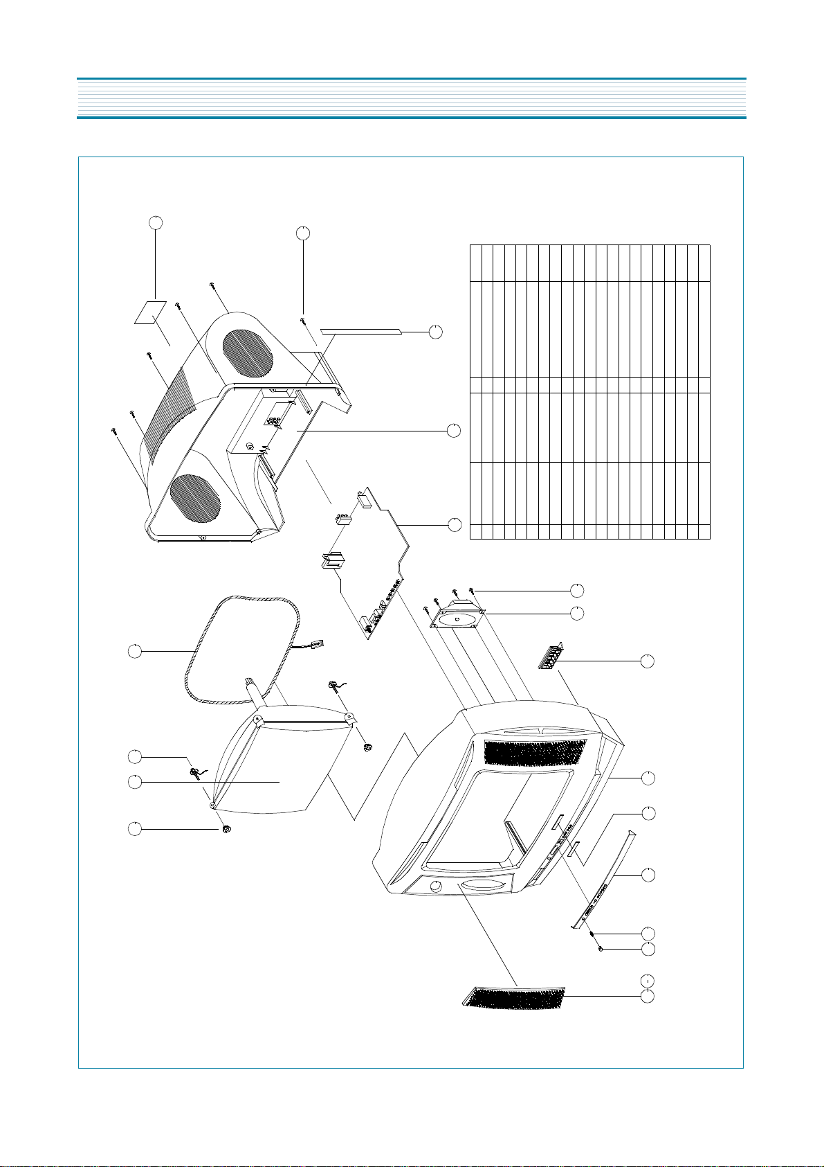
18 17
19
18
17
16
15
14
13
12
11
10
9
8
7
6
5
4
2
1-1
1
CRT
WASHER RUBBER
SPEC PLATE
COVER BACK
MAIN PCB ASSY
SCREW TAPPING
SCREW TAPPING
BUTTON
MASK FRO NT
MARK BRAND
SPRING
BUTTON POWER
PANEL C TRL
16
14
13
11
10
7
6
5
3
2
MATERI AL
REMARK S
SCREW CRT FIXING AS.
PART NA ME Q'tyPART C ODE
No
EXPLODED VIEW
 Loading...