


DTQ-14Q1FS
DAEWOO DTQ-14Q1FS, DTQ-14Q2TS, DTQ-14Q3FS, DTQ-14T1AS, DTQ-14T2FS Service Manual
...
Service Manual
Color Television
CN-201A/B
CHASSIS
MODEL:DTQ-14Q1FS, DTQ-14Q2TS
DTQ-14Q3FS, DTQ-14T1AS
DTQ-14T2FS, DTQ-20Q1FS
DTQ-20Q2FS, DTQ-20Q3FS
DTQ-20T1AS, DTQ-20T2AS
DTQ-20T1FS, DTQ-20T2FS
DTQ-20T3FS, DTQ-21T1FS
DTQ-21T2FS, DTQ-21T5FS
DTQ-21T9FS, DTQ-20T1FC
:
NTSC-M SYSTEM
✔
Caution
: In this Manual, some parts can be changed for improving, their
performance without notice in the parts list. So, if you need the
latest parts information,please refer to PPL(Parts Price List) in
Service Information Center (http://svc.dwe.co.kr).
DAEWOO ELECTRONICS CO., LT D .

FEATURES
FS (Frequency Synthesizer) Tuning System
CATV Ready
High Focus Minineck CRT
ELECTRICAL SPECIFICATIONS
POWER INPUT
AC90V - AC250V 50/60Hz
DTQ-20T1FC : 120V 60HZ ONLY
POWER RATING
14” Model 60W
20” MONO Model 70W
20” ST Model 80W
21” ST Model 80W
INTERMEDIATE FREQUENCIES
PICTURE IF CARRIER FREQUENCY 45.75MHz
SOUND IF CARRIER FREQUENCY 41.25MHz
COLOR SUB CARRIER FREQUENCY 42.17MHz
AUDIO OUTPUT RATING MONO(2W) ST(3W+3W)
SPEAKER 3W 16ohm
ANTENNA INPUT IMPEDANCE VHF/UHF 75 ohm UNBALANCED
TUNING RANGES
VHF 2 THRU 13
UHF 14 THRU 69
CATV 1 THRU 125
CONTENTS
Safety Precautions 3
Control View 6
Important Service Notes 8
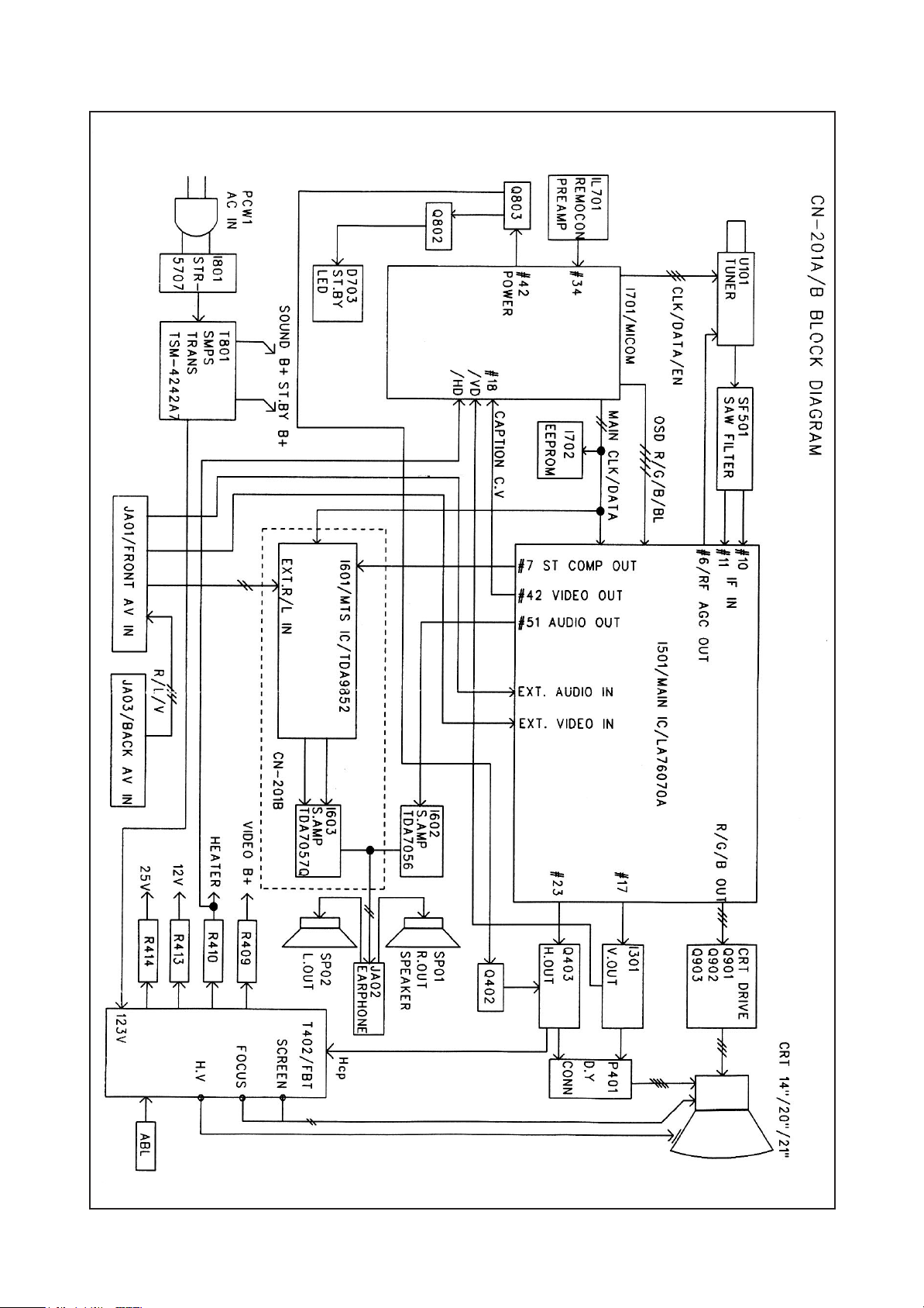
Block Diagram 9
General Adjustments 10
Operation Charaeteristic of Power Block 14
Trouble Shooting Charts 22
Description of Semiconductors 28
Printed Circuit Board Diagram 32
Exploded Views 33
Schematic Diagram with Waveforms 50
Parts List 51
Option List 65
2
PRODUCT SAFETY SERVICING GUIDELINES FOR AUDIO VIDEO PRODUCTS
DO NOT ATTEMPT TO MODIFY THIS PRODUCT IN ANY WAY. NEVER
CAUTION
PERFORM CUSTOMIZED INSTALLATIONS WITHOUT MANUFACTURER S APPROVAL.
UNAUTHORIZED MODIFICATIONS WILL NOT ONLY VOID THE WARRANTY, BUT MAY
LEAD TO YOUR BEING LIABLE FOR ANT RESULTING PROPERTY DAMAGE OR USER
INJURY.
SERVICE WORK SHOULD BE PERFORMED ONLY AFTER YOU ARE THOROUGHLY
FAMILIAR WITH ALL OF THE FOLLOWING SAFETY CHECKS AND SERVICING
GUIDELINES. TO DO OTHERWISE, INCREASES THE RISK OF POTENTIAL HAZARDS AND
INJURY TO THE USER.
WHILE SERVICING, USE AN ISOLATION TRANSFORMER FOR PROTECTION FROM A.C.
LINE SHOCK.
AFTER THE ORIGINAL SERVICE PROBLEM HAS BEEN CORRECTED, A CHECK SHOULD
BE MADE OF THE FOLLOWING:
1. BE SURE THAT ALL COMPONENTS ARE POSITIONED IN SUCH A WAY AS TO AVOID
POSSIBILITY OF ADJACENT COMPONENT SHORTS. THIS IS ESPECIALLY IMPORTANT
ON THOSE MODULES WHICH ARE TRANSPORTED TO AND FROM THE REPAIR SHOP.
2. NEVER RELEASE A REPAIR UNLESS ALL PROTECTIVE DEVICES SUCH AS
INSULATORS, BARRIERS, COVERS, SHIELDS, STRAIN RELIEFS, POWER SUPPLY
CORDS, AND OTHER HARDWARE HAVE BEEN REINSTALLED PER ORIGINAL DESIGN.
BE SURE, THAT THE SAFETY PURPOSE OF THE POLARIZED LINE PLUG HAS NOT
BEEN DEFEATED.
3. SOLDERING MUST BE INSPECTED TO DISCOVER POSSIBLE COLD SOLDER JOINTS,
SOLDER SPLASHES OF SHARP SOLDER POINTS. BE CERTAIN TO REMOVE ALL
LOOSE FOREIGN PARTICLES.
4. CHECK FOR PHYSICAL EVIDENCE OF DAMAGE OR DETERIORATION TO PARTS AND
COMPONENTS, FOR FRAYED LEADS, DAMAGED INSULATION (INCLUDING A.C. CORD),
AND REPLACE IF NECESSARY. FOLLOW ORIGINAL LAYOUT, LEAD LENGTH AND
DRESS.
5. NO LEAD OR COMPONENT SHOULD TOUCH A RECEIVING TUBE OR A RESISTOR
RATED AT 1 WATT OR MORE. LEAD TENSION AROUND PROTRUDING METAL
SURFACES MUST BE AVOIDED.
6. ALL CRITICAL COMPONENTS SUCH AS FUSES, FLAMEPROOF RESISTOR,
CAPACITORS, ETC. MUST BE REPLACED WITH EXACT FACTORY TYPES. DO NOT USE
REPLACEMENT COMPONENTS OTHER THAN THOSE SPECIFIED OR MAKE
UNRECOMMENDED CIRCUIT MODIFICATIONS.
7. AFTER RE-ASSEMBLY OF THE STE ALWAYS PERFORM AN A.C. LEAKAGE TEST ON
ALL EXPOSED METALLIC PARTS OF THE CABINET. (THE CHANNEL SELECTOR KNOB,
ANTENNA TERMINALS, HANDLE AND SCREWS) TO BE SURE THE SET IS SAFE TO
OPERATE WITHOUT DANGER OF ELECTRICAL SHOCK.
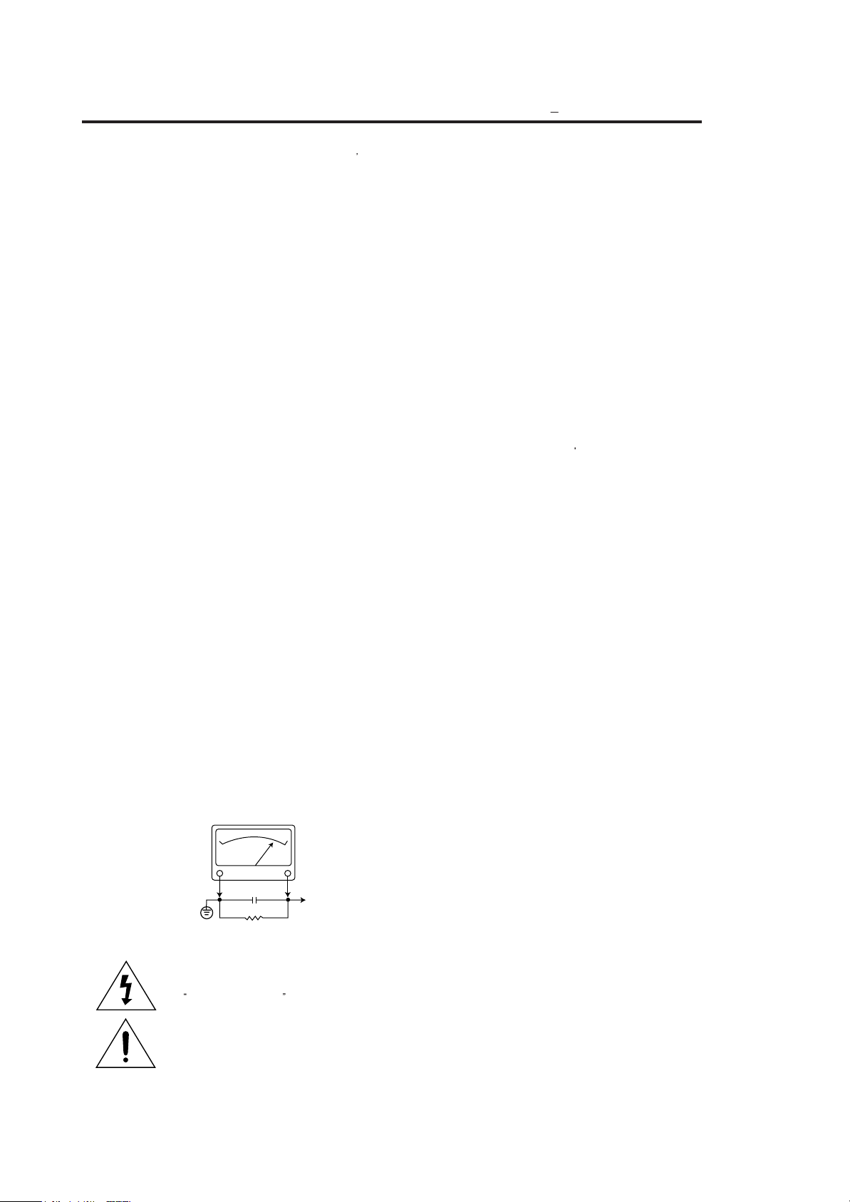
ISOLATION TRANSFORMER DURING THIS TEST
HAVING 5000 OHMS PER VOLT OR MORE SENSITIVITY, IN THE FOLLOWING MANNER :
CONNECT A 1500 OHM 10 WATT RESISTOR, PARALLELED BY A .15 MFD. 150V A.C.
TYPE CAPACITOR BETWEEN A KNOWN GOOD EARTH GROUND (WATER POPE,
CONDUIT, ETC.) AND THE EXPOSED METALLIC PARTS, ONE AT A TIME. MEASURE
THE A.C. VOLTAGE ACROSS THE COMBINATION OF 1500 OHM RESISTOR AND .15
MFD CAPACITOR. REVERSE THE A.C. PLUG AND REPEAT A.C. VOLTAGE
MEASUREMENTS FOR EACH EXPOSED METALLIC PART. VOLTAGE MEASURED MUST
NOT EXCEED .75 VOLTS R.M.S THIS CORRESPONDS TO 0.5 MILLIAMP A.C. NAY VALUE
EXCEEDING THIS LIMIT CONSTITUTES A POTENTIAL SHOCK HAZARD AND MUST BE
CORRECTED IMMEDIATELY.
SUBJECT : GRAPHIC SYMBOLS
:
SAFETY CHECKS
SUBJECT:FIRE & SHOCK HAZARD
A.C. VOLTMETER
A.C. VOLTMETER
GOOD EARTH GROUND
SUCH AS THE WATER
PIPE, CONDUIT, ETC.
THE LIGHTNING FLASH WITH ARROWHEAD SYMBOL, WITHIN
AN EQUILATERAL TRIANGLE, IS INTENDED TO ALERT THE
SERVICE PERSONNEL TO THE PRESENCE OF UNINSULATED
DANGEROUS VOLTAGE THAT MAY BE OF SUFFICIENT
MAGNITUDE TO CONSTITUTE A RISK OF ELECTRIC SHOCK.
THE EXCLAMATION POINT WITHIN AN EQUILATERAL
TRIANGLE IS INTENDED TO ALERT THE SERVICE
PERSONNEL TO THE PRESENCE OF IMPORTANT SAFETY
INFORMATION ON SERVICE LITERATURE.
0.15µF
1500 OHM
10WATT
DO NOT USE A LINE
USE AN A.C. VOLTMETER,
PLACE THIS PROBE
ON EACH EXPOSED
METAL PART
SUBJECT : X-RADIATION
1. BE SURE PROCEDURES AND INSTRUCTIONS TO ALL SERVICE PERSONNEL COVER
2. ONLY FACTORY SPECIFIED C.R.T ANODE CONNECTORS MUST BE USED.
3. IT IS ESSENTIAL THAT SERVICE PERSONNEL HAVE AVAILABLE AN ACCURATE AND
4. WHEN THE HIGH VOLTAGE CIRCUITRY IS OPERATING PROPERLY THERE IS NO
5. WHEN TROUBLESHOOTING AND MAKING TEST MEASUREMENTS IN A PRODUCT WITH
6. REFER TO HV, B + AND SHUTDOWN ADJUSTMENT PROCEDURES DESCRIBED IN THE
SUBJECT : IMPLOSION
1. ALL DIRECT VIEWED PICTURE TUBES ARE EQUIPPED WITH AN INTEGRAL IMPLOSION
2. USE ONLY RECOMMENDED FACTORY REPLACEMENT TUBES.
SUBJECT : TIPS ON PROPER INSTALLATION
1. NEVER INSTALL ANY PRODUCT IN A CLOSED-IN RECESS, CUBBYHOLE OR CLOSELY
2. AVOID CONDITIONS OF HIGH HUMIDITY SUCH AS: OUTDOOR PATIO INSTALLATIONS
3. AVOID PLACEMENT WHERE DRAPERIES MAY OBSTRUCT REAR VENTING. THE
4. WALL AND SHELF MOUNTED INSTALLATIONS USING A COMMERCIAL MOUNTING KIT,
5. CAUTION CUSTOMERS AGAINST THE MOUNTING OF A PRODUCT ON SLOPING SHELF
6. A PRODUCT ON A ROLL-ABOUT CART SHOULD BE STABLE ON ITS MOUNTING TO THE
7. CAUTION CUSTOMERS AGAINST THE USE OF A CART OR STAND WHICH HAS NOT
8. CAUTION CUSTOMERS AGAINST THE USE OF EXTENSION CORDS, EXPLAIN THAT A
950ART94
1009
THE SUBJECT OF X-RADIATION. THE ONLY POTENTIAL SOURCE OF X-RAYS IN
CURRENT T.V. RECEIVERS IS THE PICTURE TUBE. HOWEVER, THIS TUBE DOES NOT
EMIT X-RAYS WHEN THE HIGH VOLTAGE IS AT THE FACTORY SPECIFIED LEVEL. THE
PROPER VALUE IS GIVEN IN THE APPLICABLE SCHEMATIC. OPERATION AT HIGHER
VOLTAGES MAY CAUSE A FAILURE OF THE PICTURE TUBE OR HIGH VOLTAGE
SUPPLY AND, UNDER CERTAIN CIRCUMSTANCES, AMY PRODUCE RADIATION IN
EXCESS OF DESIRABLE LEVELS.
DEGAUSSING SHIELDS ALSO SERVE AS X-RAY SHIELD IN COLOR SETS. ALWAYS REINSTALL THEM.
RELIABLE HIGH VOLTAGE METER. THE CALIBRATION OF THE METER SHOULD BE
CHECKED PERIODICALLY AGAINST A REFERENCE STANDARD. SUCH AS THE ONE
AVAILABLE AT YOUR DISTRIBUTOR.
POSSIBILITY OF AN X-RADIATION PROBLEM. EVERY TIME A COLOR CHASSIS IS
SERVICED, THE BRIGHTNESS SHOULD BE RUN UP AND DOWN WHILE MONITORING
THE HIGH VOLTAGE WITH A METER TO BE CERTAIN THAT THE HIGH VOLTAGE DOES
NOT EXCEED THE SPECIFIED VALUE AND THAT IT IS REGULATING CORRECTLY. WE
SUGGEST THAT YOU AND YOUR SERVICE ORGANIZATION REVIEW TEST
PROCEDURES SO THAT VOLTAGE REGULATION IS ALWAYS CHECKED AS A
STANDARD SERVICING PROCEDURE, AND THAT THE HIGH VOLTAGE READING BE
RECORDED ON EACH CUSTOMER
A PROBLEM OF EXCESSIVE HIGH VOLTAGE, AVOID BEING UNNECESSARILY CLOSE
TO THE PICTURE TUBE AND THE HIGH VOLTAGE SUPPLY. DO NOT OPERATE THE
PRODUCT LONGER THAN IS NECESSARY TO LOCATE THE CAUSE OF EXCESSIVE
VOLTAGE.
APPROPRIATE SCHEMATIC AND DIAGRAMS (WHERE USED).
PROTECTION SYSTEM. BUT CARE SHOULD BE TAKEN TO AVOID DAMAGE DURING
INSTALLATION. AVOID SCRATCHING THE TUBE. OF SCRATCHED REPLACE IT.
FITTING SHELF SPACE, OVER OR CLOSE TO HEAT DUCT, OR IN THE PATH OF
HEATED AIR FLOW.
WHERE DEW IS A FACTOR, NEAR STEAM RADIATORS WHERE STEAM LEAKAGE IS A
FACTOR, ETC.
CUSTOMER SHOULD ALSO AVOID THE USE OF DECORATIVE SCARVES OR OTHER
COVERINGS WHICH MIGHT OBSTRUCT VENTILATION.
MUST FOLLOW THE FACTORY APPROVED MOUNTING INSTRUCTIONS. A PRODUCT
MOUNTED TO A SHELF OR PLATFORM MUST RETAIN ITS ORIGINAL FEET (OR THE
EQUIVALENT THICKNESS IN SPACERS)TO PROVIDE ADEQUATE AIR FLOW ACROSS
THE BOTTOM, BOLTS OR SCREWS USED FOR FASTENERS MUST NOT TOUCH ANY
PARTS OR WIRING. PERFORM LEAKAGE TEST ON CUSTOMIZED INSTALLATIONS.
OR A TILTED POSITION, UNLESS THE PRODUCT IS PROPERLY SECURED.
CART. CAUTION THE CUSTOMER ON THE HAZARDS OF TRYING TO ROLL A CART
WITH SMALL CASTERS ACROSS THRESHOLDS OR DEEP PILE CARPETS.
BEEN LISTED BY UNDERWRITERS LABORATORIES. INC. FOR USE WITH THEIR
SPECIFIC MODEL OF TELEVISION RECEIVER OR GENERICALLY APPROVED FOR USE
WITH T.V.S OF THE SAME OR LARGER SCREEN SIZE.
FOREST OF EXTENSIONS SPROUTING FROM A SINGLE OUTLET CAN LEAD TO
DISASTROUS CONSEQUENCES TO HOME AND FAMILY.
S INVOICE.
3
Product safety servicing guidelines for color
television receivers
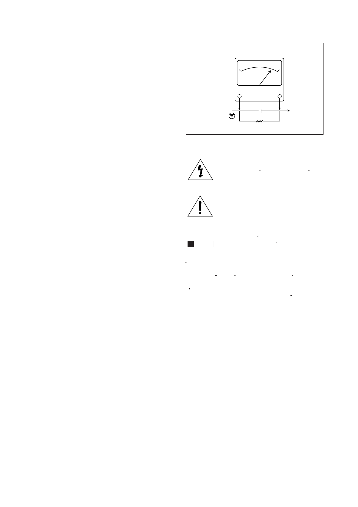
A.C. VOLTMETER
CAUTION :
way. Unauthorized modifications will not only void the
warranty, but may lead to your being liable for any
resulting property damage or user injury.
Service work should be performed only after you are
thoroughly familiar with all of the following safety checks
and servicing guidelines. To do otherwise, increases the
risk of potential hazards and injury to the user.
Do not attempt to modify this product in any
SAFETY CHECKS
After the original service problem has been corrected, a
check should be made of the following:
SUBJECT : FIRE & SHOCK HAZARD
1. Be sure that all components are positioned in such a
way as to avoid possibility of adjacent component
shorts. This is especially important on those chassis
which are transported to and from the repair shop.
2. Never release a repair unless all protective devices
such as insulators, barriers, covers, shields, strain
reliefs, and other hardware have been reinstalled per
original design.
3. Soldering must be inspected to discover possible cold
solder joints, frayed leads, damaged insulation
(including A.C. cord), solder splashes or sharp solder
points. Be certain to remove all loose foreign particals.
4. Check for physical evidence of damage or deterioration
to parts and components, and replace if necessary
follow original layout, lead length and dress.
5. No leads or components should touch a receiving tube
or a resistor rated at 1 watt or more. Lead tension
around protruding metal surfaces must be avoided.
6. All critical components such as fuses, flameproof
resistors, capacitors, etc. must be replaced with exact
factory types. Do not use replacement components
other than those specified or make unrecommended
circuit modifications.
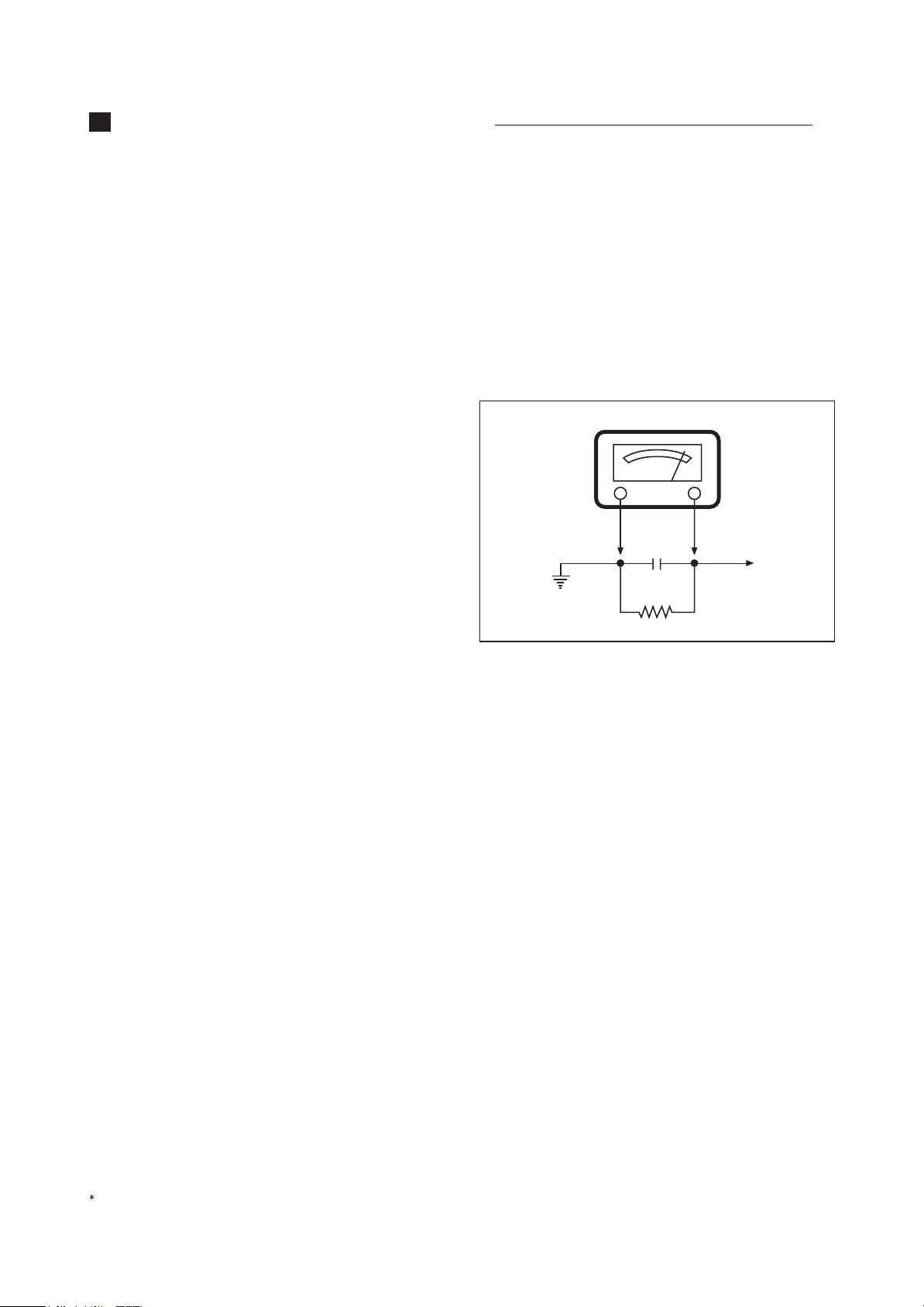
7. After re-assembly of the set always perform an A.C.
leakage test on all exposed metallic parts of the
cabinet, (the channel selector knob, antenna terminals,
handle and screws) to be sure the set is safe to operate
without danger of electrical shock. Do not use a line
isolation transformer during this test. Use an A.C.
voltmeter, having 5000 ohms per volt or more
sensitivity, in the following manner : connect a 1500
ohm 10 watt resistor, paralleled by a 15 mfd. 150V A.C.
type capacitor between a known good earth ground
(9water pipe, conduit, etc.) and the exposed metallic
parts, one at a time. Measure the A.C. voltage across
the combination of 1500 ohm resistor and 0.15 MFD
capacitor. Reverse the A.C. plug and repeat A.C.
voltage measurements for each exposed metallic part.
Voltage measured must not exceed 0.75 volts R.M.S.
This corresponds to 0.5 milliamp A.C. Any value
exceeding this limit constitutes a potential shock hazard
and must be corrected immediately.
Good earth ground,
such as the water
pipe, conduit, etc.
0.15µF
••
1500 OHM
10WATT
Place this probe
on each exposed
metal part.
GRAPHIC SYMBOLS :
The lightning flash with arrowhead symbol,
within an equilateral triangle, is intended to
alert the service personnel to the presence
of uninsulated
may be of sufficienty magnitude to
constitute a risk of electric shock.
The exclamation point within an equilateral
triangle is intended to alert the service
personnel to the presence of important
safety information in service literature.
Fuse symbol is printed on pcb adjacent to
the fuse, with
FUSE AS MARKED
explained in the service manual with the
following wording or equivalent.
CAUTION : FOR CONTINUED PROTECTION AGAINST
FIRE HAZARD, REPLACE ONLY WITH SAME TYPE 4A,
125V FUSE
PROTECTION PERMANENTE CONTRE LES RISQUES
D
INCENDIE, REMPLACER UNIQUEMENT PAR UN
FUSIBLE DE MEME TYPE ET DE 4A, 125V
and ATTENTION: AFIN D ASSU UNE
dangerous voltage that
RISK OF FIRE REPLACE
. The symbol is
.
SUBJECT : X-RADIATION
1. Be sure procedures and instructions to all service
personnel cover the subject of X-rays in current T.V.
receivers is the picture tube. However, this tube does
not emit X-rays when the high voltage is at the factory
specified level. The proper value is given in the
applicable schematic. Operation at higher voltages may
cause a failure of the picture tube or high voltage
supply and, under certain circumstances, may produce
radiation in excess of desirable levels.
2. Only factory specified C.R.T. anode connectors must
be used. Degaussing shields also serve as X-ray shield
in color sets. Always re-install them.
3. It is essential that the serviceman has available an
accurate and reliable high voltage meter. The
calibration of the meter should be checked perio dically against a reference standard. Such as the one
available at your distributor.
4. When the high voltage circuitry is operating properly
there is no possibility of an X-radiation problem. Every
time a color chassis is serviced, the brightness should
be run up and down while monitoring the high voltage
4

with a meter to be certain that the high voltage does not
exceed the specified value and that it is regulating
correctly. We suggest that you and your service
organization review test procedures so that voltage
regulation is always checked as a standard servicing
procedure. And that the high voltage reading be recorded
on each customer
5. When troubleshooting and making test measurements
in a receiver with a problem of excessive high voltage,
avoid being unnecessarily close to the picture tube and
the high voltage compartment.
Do not operate the chassis longer than is necessary to
locate the cause of excessive voltage.
6. Refer to HV, B+and Shutdown adjustment procedures
described in the appropriate schematic and
diagrams(where used).
s invoice.
SUBJECT : IMPLOSION
1. All direct viewed picture tubes are equipped with an
integral implosion protection system, but care should be
taken to avoid damage during installation. Avoid
scratching the tube. If scratched, replace it.
2. Use only recommended factory replacement tubes.
SUBJECT : TIPS ON PROPER
INSTALLATION
1. Never install any receiver in closed-in recess,
cubbyhole or closely fitting shelf space over, or close to
heat duct, or in the path of heated air flow.
2. Avoid conditions of high humidity such as : Outdoor
patio installations where dew is a factor. Near steam
radiators where steam leakage is a factor, etc.
3. Avoid placement where draperies may obstruct rear
venting. The customer should also avoid the use of
decorative scarves or other coverings which might
obstruct ventilation.
4. Wall and shelf mounted installations using a
commercial mounting kit, must follow the factory
approved mounting instructions. A receiver mounted to
a shelf or platform must retain its original feet(or the
equivalent thickness in spacers) to provide adequate
are flow across the bottom, bolts or screws used for
fasteners must not touch and parts or wiring. Perform
leakage test on customized installations.
5. Caution customers against the mounting of a receiver
on sloping shelf or a tilted position, unless the receiver
is properly secured.
6. A receiver on a roll-about cart should be stable on its
mounting to the cart. Caution the customer on the
hazards of trying to roll a cart with small casters across
thresholds or deep pile carpets.
7. Caution customers against the use of a cart or stand
which has not been listed by underwriters laboratories,
inc. For use with their specific model of television
receiver or generically approved for use with T.V.
the same or larger screen size.
s of
5

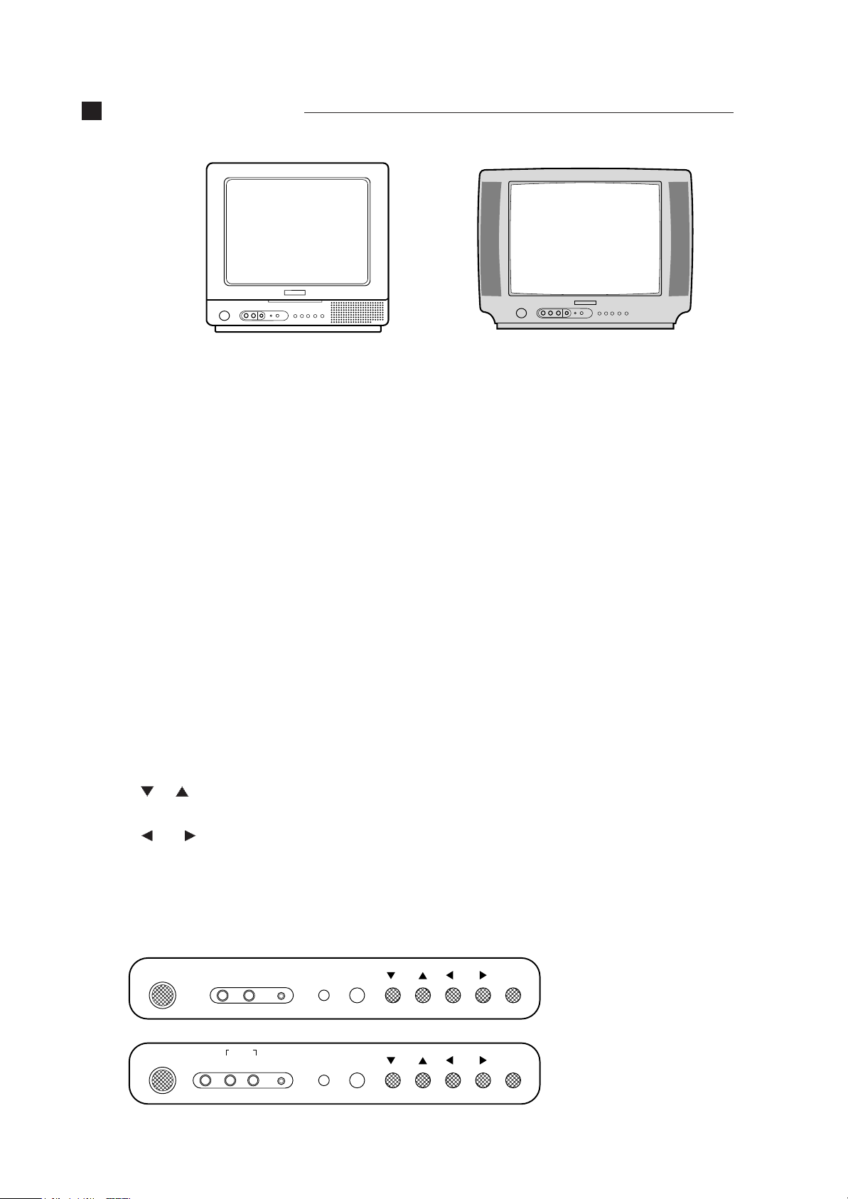
CONTROL VIEW
MONO MODEL
STEREO MODEL
Overview of Your Equipment
Your TV comes with a remote control. The section below summarizes the buttons, controls, and terminals that you
will use with your TV.
Your TV's Front Panel
1 POWER
Use this button to turn your TV on or off.
2 VIDEO IN jack
Use this jack to receive a video signal from another A/V component.
3 AUDIO IN jack
MONO MODEL use this jack to receive an audio signal from another A/V component. But, STEREO MODEL use
this jack to receive audio L/R signal from another A/V component.
4 EARPHONE IN jack
Use this jack to receive a audio signal from your TV.
5 STAND-BY (red) indicator
This indicator lights up when the power is off.
6 Remote control receiver
This receiver receives a signal from your remote control. Don’t block it.
7 CH
Use these buttons to change channels on your TV, or to select items in the menu system.
8 VOL
Use these buttons to change your TV’s volume, to activate selections in the menu system, or to change audio and
video settings.
9 MENU
Use this button to turn the TV’s menu system on and off.
MONO MODEL
POWER VIDEO AUDIO
STEREO MODEL
POWER VIDEO
AUDIO
L R
EARPHONE
EARPHONE
STAND-BY
STAND-BY
CH
CH
VOL
VOL
MENU
MENU
6

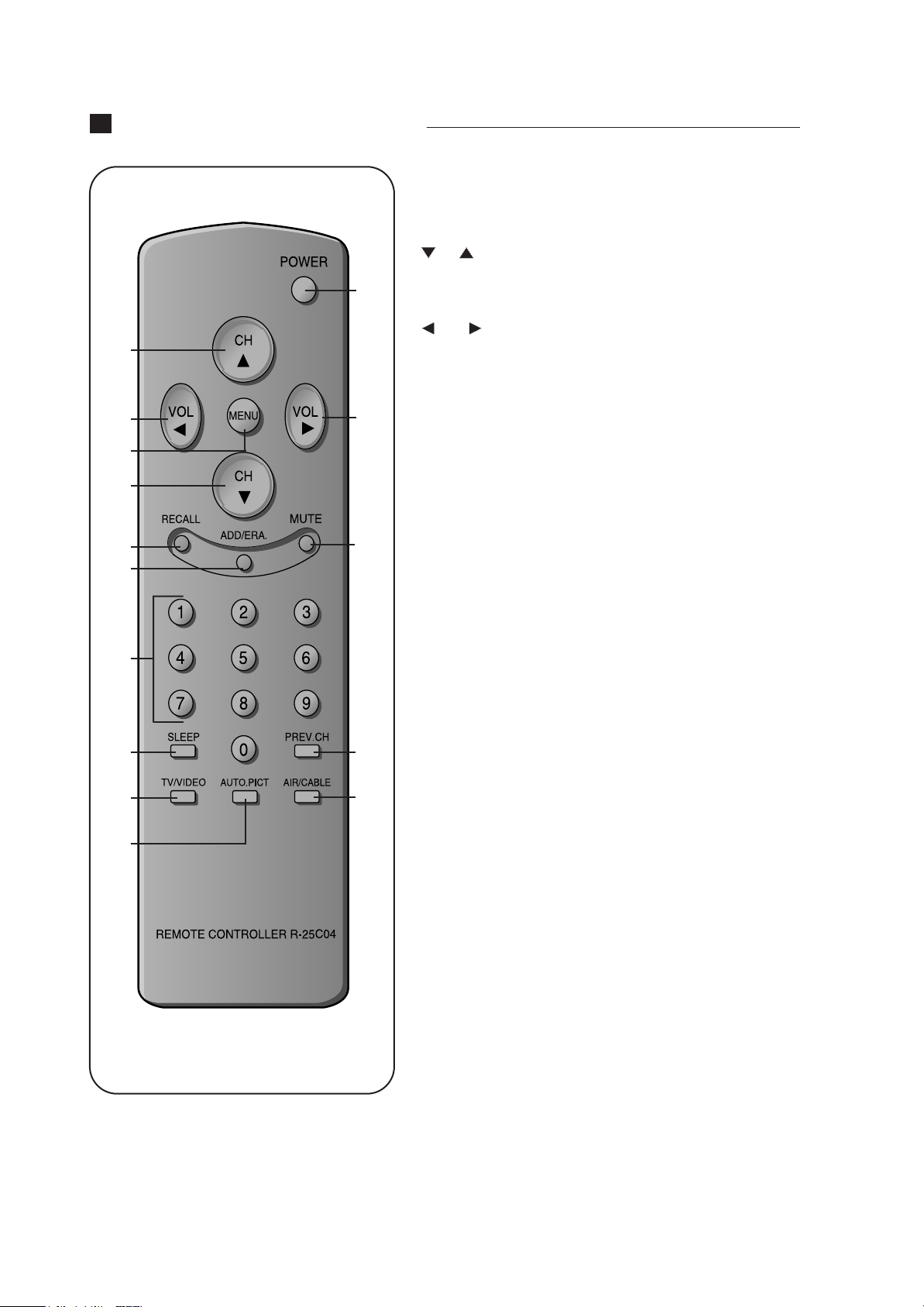
REMOTE CONTROL UNIT
1 POWER
2 CH
1
3 VOL
2
Use this button to turn your TV on or off.
Use these buttons to change channels on your TV, or select items in
the menu system.
Use these buttons to change your TV's volume, to activate selections
in the menu system, or to change audio and video settings.
3
4
2
5
6
8
9
11
12
4 MENU
3
5 RECALL
6 ADD/ERA.
7
7 MUTE
8 0-9
9 SLEEP
10PREV. CH
10
13
11 TV/VIDEO
Use this button to turn the TV's menu system on and off.
Press this button to display the channel number.
Use this button to add a channel to the TV's memory or erase the
channel from memory.
Use to turn the TV's sound on and off.
Use these buttons to change channels.
Use this button to program the TV to turn off after a certain time.
Press this button to return to the previous channel you were watching. If you have set Favorite Ch, this key operates to Favorite function.
Use this button to select TV or VIDEO mode.
12 AUTO. PICT
Press this button to return the TV's video settings to their original
level.
13 AIR/CABLE
Use the button to set up your TV to receive signals from an antenna
(AIR) or a cable system (CABLE).
7
CONTROL VIEW
MONO MODEL
STEREO MODEL
Overview of Your Equipment
Your TV comes with a remote control. The section below summarizes the buttons, controls, and terminals that you
will use with your TV.
Your TV's Front Panel
1 POWER
Use this button to turn your TV on or off.
2 VIDEO IN jack
Use this jack to receive a video signal from another A/V component.
3 AUDIO IN jack
MONO MODEL use this jack to receive an audio signal from another A/V component. But, STEREO MODEL use
this jack to receive audio L/R signal from another A/V component.
4 EARPHONE IN jack
Use this jack to receive a audio signal from your TV.
5 STAND-BY (red) indicator
This indicator lights up when the power is off.
6 Remote control receiver
This receiver receives a signal from your remote control. Don’t block it.
7 CH
Use these buttons to change channels on your TV, or to select items in the menu system.
8 VOL
Use these buttons to change your TV’s volume, to activate selections in the menu system, or to change audio and
video settings.
9 MENU
Use this button to turn the TV’s menu system on and off.
MONO MODEL
POWER VIDEO AUDIO
STEREO MODEL
POWER VIDEO
AUDIO
L R
EARPHONE
EARPHONE
STAND-BY
STAND-BY
CH
CH
VOL
VOL
MENU
MENU
6
REMOTE CONTROL UNIT
1 POWER
2 CH
1
3 VOL
2
Use this button to turn your TV on or off.
Use these buttons to change channels on your TV, or select items in
the menu system.
Use these buttons to change your TV's volume, to activate selections
in the menu system, or to change audio and video settings.
3
4
2
5
6
8
9
11
12
4 MENU
3
5 RECALL
6 ADD/ERA.
7
7 MUTE
8 0-9
9 SLEEP
10PREV. CH
10
13
11 TV/VIDEO
Use this button to turn the TV's menu system on and off.
Press this button to display the channel number.
Use this button to add a channel to the TV's memory or erase the
channel from memory.
Use to turn the TV's sound on and off.
Use these buttons to change channels.
Use this button to program the TV to turn off after a certain time.
Press this button to return to the previous channel you were watching. If you have set Favorite Ch, this key operates to Favorite function.
Use this button to select TV or VIDEO mode.
12 AUTO. PICT
Press this button to return the TV's video settings to their original
level.
13 AIR/CABLE
Use the button to set up your TV to receive signals from an antenna
(AIR) or a cable system (CABLE).
7
IMPORTANT SERVICE NOTES
1. X-RAY RADIATION PRECAUTION
1) Excessive high voltage can produce potentially
hazardous X-RAY RADIATION. To avoid such hazards,
the high voltage must not be above the specified limit.
The nominal value of the high voltage of this receiver is
24.4kv at zero beam current (minimum brightness)
under a 120V AC power source. The high voltage must
not, under any circumstances, exceed 27kv (28.5kv).
Each time a receiver requires servicing, the high
voltage should be checked following the HIGH
VOLTAGE CHECK procedure on page 6 of this
manual. It is recommended as a parts of the service
record. It is important to use an accurate and reliable
high voltage meter.
2) This receiver is equipped with X-RADIATION
PROTECTION circuit which prevents the receiver from
producing an excessively high voltage even if the
B+voltage increases abnormally. Each time the
receiver is serviced, X-RADIATION PROTECTION
circuit must be checked to determine that the circuit is
properly functioning, following the X-RADIATION
PROTECTION CIRCUIT CHECK procedure on page 6
of this manual.
3) The only source of X-RAY RADIATION in this TV
receiver is the picture tube. For continued X-RAY
RADIATION protection, the replacement tube must be
exactly the same type tube as specified in the parts list.
4) Some parts in this receiver have special safety-related
characteristics for X-RAY RADIATION protection. For
continued safety, parts replacement should be
undertaken only after referring to the PRODUCT
SAFETY NOTICE below.
2. SAFETY PRECAUTION
WARNING
: Service should not be attempted by anyone
unfamiliar with the necessary precaution on this receiver.
The following are the necessary precaution to be
observed before servicing.
1) Since the chassis of this receiver has hazardous
potential to ground whenever the receiver is plugged in
(floating chassis), an isolation transformer must be
used during servicing to avoid shock hazard.
2) Always discharge the picture tube anode to the CRT
conductive coating the picture tube. The picture tube is
highly evacuated and if broken, glass fragments will be
violently expelled. Use shatterproof goggles and keep
picture tube away from the body while handling.
3) When placing chassis in the cabinet, always be certain
that all the protective devices are put back in place,
such as; nonmetallic control knobs, insulating covers,
shields, isolation resistor-capacitor network, etc.
4) Before returning the set to the customer, always
perform an AC leakage current check on the exposed
metallic parts of the cabinet, such as antennas,
terminals, screw-heads, metal overlays, control shafts
etc. to be sure the set is safe to operate without
danger of electrical shock. Plug the AC line cord
directly into a 120V AC outlet (do not use a line isola-
Minimum brightness
tion transformer during this check). Use an AC
voltmeter having 5000 ohms per volt or more sensitivity in the following manner.
Connect at 1500 ohm 10 watt resistor, paralleled by a
0.15 mfd. AC type capacitor, between a known good
earth ground (water pipe, conduit etc.) and the exposed
metallic parts, one at a time. Measure the AC voltage
across the combination of 1500 ohm resistor and 0.15
mfd capacitor. Voltage measured must not exceed 0.3
volts RMS. This corresponds to 0.2 millliamp. AC. Any
value exceeding the limit constitutes a potential shock
hazard and must be corrected immediately.
AC VOLT METER
0.15MFD
Place this probe
on each exposed
metallic part.
Good earth ground
such as d water
pipe, conduit, etc.
1500 ohm
10watt
3. PRODUCT SAFETY NOTICE
Many electrical and mechanical parts in this chassis have
special safety-related characteristics. These
characteristics are often passed unnoticed by a visual
inspection and the protection afforded by them cannot
necessarily be obtained by using replacement
components rated for higher voltage, wattage, etc.
Replacement parts which have these special safety
characteristics are identified in this manual and its
supplements; electrical components having such features
are identified by shading on the schematic diagram and
the parts list.
Before replacing any of these components, read the parts
list in this manual carefully. The use of substitute
replacement parts which do not have the same safety
characteristics as specified in the parts list may create Xray radiation or other hazards.
4. SERVICE NOTES
1) When replacing parts or circuit boards, clamp or bend
the lead wires to terminals before soldering.
2) When replacing a high wattage resistor (metal oxide
film resistor) in the circuit board, keep the resistor min
1/2 inch away form circuit board.
3) Keep wires away from high voltage or high temperature
components.
8
9

GENERAL ADJUSTMENTS
1. GENERAL
In the majority of cases, all color televisions will need only
slight touch-up adjustment upon installation. Check the
basic characteristics such as height, focus and sub- basic
characteristics such as height, focus and sub- bright.
Observe the picture for good black and white details
without objectionable color shading. If color shading is
evident, demagnetize the receiver. If color shading still
persists, perform purity and convergence adjustments.
This should be all that is necessary to achieve Optimum
receiver performance.
2. SCREEN ADJUSTMENT
1) Turn on TV
2) Press the S2 key of Service Remocon to make the One
Horizontal Line
3) Adjust the Screen adj. VR of FBT so that the One
Horizontal Line may be cut off.
4) Press the S2 key of Servic Remocon to be normal.
3. FOCUS ADJUSTMENT
1) Receive the Retma Pattern.
2) Adjust the FOCUS adj. VR to optain the clearest
picture.
4. HORIZONTAL CENTER ADJUSTMENT
1) Receive the Retma Pattern.
2) Press the S6(59H) key of Service Remocon, select
H.Phase, then adjust step so that the L/R Width of
picture be alike.
3) Press the RECALL key to store.
4) Initial value of D.P : 5
7. X-RADIATION PROTECTION CIRCUIT TEST
When service has been performed on the horizontal
deflection system, high voltage system or B+system. the
X-RADIATION protection circuit must be tested for proper
operation as follows:
1) Operate receiver for at least 15 minutes at 120V AC
line.
2) Adjust all customer controls for normal picture and
sound.
3) Short R411(X-RAY Short test), and remove short clip.
4) If the operation of horizontal osc. does not stop in step
The circuit must be repaired, before the set is returned
to the customer.
8. White balance ADJUSTMENT
1) Press the S8 key of SERVICE REMOCON, select W/B
2) Adjust the R/G/B BIAS of Low BEAM in order that the
R/G/B BIAS of Low BEAM may meet with coordinates.
3) Adjust the R/B DRIVE of High BEAM in order that the
R/B DRIVE of High BEAM may meet with coordinates.
4) Confirm the LOW BEAM, HIGH BEAM alternately.
5) Press the RECALL key to store.
9. SUB-BRIGHTNESS ADJUSTMENT
1) Receive the Retma Pattern.
2) Press the S9(5CH) key of Service Remocon, adjust
Bright in order that the gradation pattern may set 18%.
3) Press the RECALL key to store.
4) Initial value of D.P :25
5. VERTICAL CENTER ADJUSTMENT
1) Receive the Retma Pattern.
2) Press the S6(59H) key of Service Remocon, select
V.DC, then adjust V.DC so that the horizontal line of
RETMA PATTERN’S center may meet with the
mechanical CENTER of CRT.
3) Press the RECAL key to store.
4) Initial value of D.P:35
6. VERTICAL HIGHT ADJUSTMENT
1) Receive the Retma Pattern.
2) Press the S6(59H) key of Service Remocon, select
V.Size, then adjust V.Size so that the center of
circumference of big circle may meet with the upper
and lower sides of the screen.
3) Press the RECALL key to store.
4) Initial of value of D.P :35
10
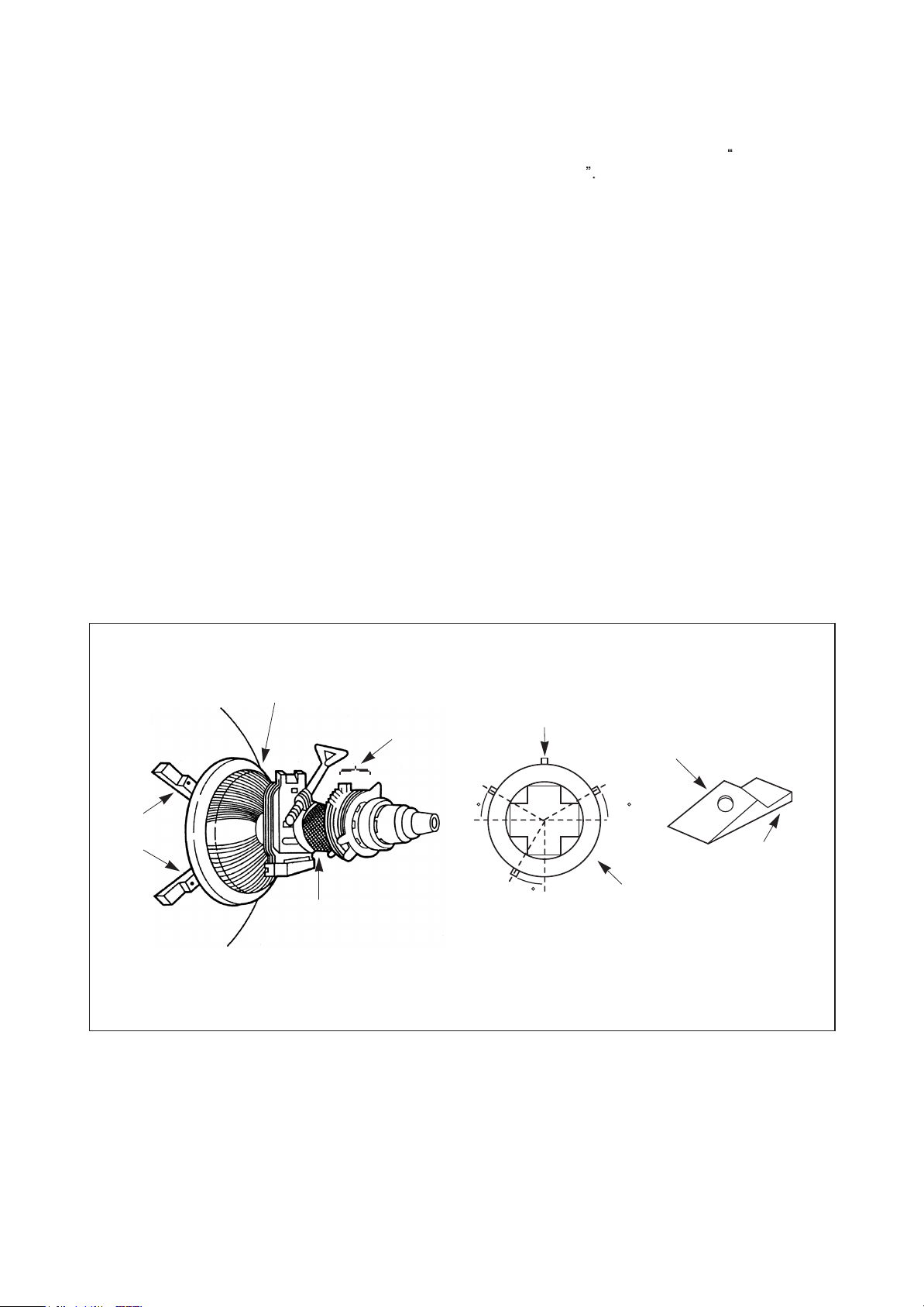
10. CONVERGENCE MAGNET ASSEMBLY
POSITIONING
If Convergence magnet assembly and rubber wedges
need mechanical positioning follow figure 2.
10-1. COLOR PURITY ADJUSTMENT
NOTE
1) Demagnetize the picture tube with a degaussing coil.
2) Adjust the CONTRAST and BRIGHTNESS controls to
3) Adjust RED and BLUE Bias controls Service Remocon
4) Loosen the clamp screw holding the yoke, and slide the
5) Remove the Rubber Wedges.
6) Rotate and spread the tabs of the purity magnet (See
7) Move the yoke slowly forward until a uniform green
: Before attempting any purity adjustments, the
receiver should be operated for at least 15
minutes.
maximum
to provide only a green raster. Adjust the GREEN BIAS
control Service Remocon if necessary.
yoke backward to provide vertical green belt(zone)in
the picture screen.
figure 2) around the neck of the picture tube until the
green belt is in the center of the screen. At the same
time, center the raster vertically.
screen is obtained. Tighten the clamp screw of the yoke
temporarily.
8) Check the purity of the red and blue raster by adjusting
the BIAS controls.
9) Obtain a white raster, referring to
ADJUSTMENT
10) Proceed with convergence adjustment.
White Bodance
RUBBER
WEDGES
PICTURE TUBE
DEFLECTION
YOKE
GLASS CLOTH
TAPE
CONVERGENCE
MAGNET ASS'Y
TEMPORARY
MOUNTING
30 30
30
Fig. 2 Rubber Wedges Location
RUBBER
WEDGES
ADHESIVE
DEF.
YOKE
11

10-2. CONVERGENCE ADJUSTMENTS
NOTE
: Before attempting any purity adjustments, the
receiver should be operated for at least 15
minutes.
A. CENTER CONVERGENCE ADJUSTMENT
1) Receive crosshatch pattern with a crosshatch signal
generator.
2) Adjust the BRIGHTNESS and CONTRAST Controls for
a good picture.
3) Adjust two tabs of the 4-Pole Magnets to change the
angle between them (See Fig. 3) and superimpose red
and blue vertical lines in the center area of the picture
screen. (See Fig. 4)
4) Turn both tabs at the same time keeping their angles
constant to superimpose red and blue horizontal lines
at the center of the screen. (See Fig. 4)
5) Adjust two tabs of 6-Pole Magnets to superimpose
red/blue line with green on top of each other. Adjusting
the angle affects the vertical lines and rotating both
magnets affects the horizontal lines.
6) Repeat adjustments 3), 4), 5) keeping in mind red,
green and blue movement, because 4-Pole Magnets
and 6-Pole Magnets interact and make dot movement
complex.
B. CIRCUMFERENCE CONVERGENCE ADJUSTMENT
: This adjustment requires Rubber Wedge Kit.
NOTE
1) Loosen the clamping screw on deflection yoke to allow
the yoke to tilt.
2) Place a wedge as shown in figure 2 temporarily. (Do
not remove cover paper on adhesive part of the
wedge.)
3) Tilt front of the deflection yoke up or down to obtain
better convergence in circumference. (See Fig. 4) Push
the mounting wedge into the space between picture
and the yoke to hold the yoke temporarily.
4) Place other wedge into bottom space and remove the
cover paper to stick.
5) Tilt front of the yoke right or left to obtain better
convergence in cicumference. (See Fig. 4)
6) Hold the yoke position and put another wedge in either
upper space. Remove cover paper and stick the wedge
on picture tube to hold the yoke.
7) Detach the temporarily mounted wedge and put it in
another upper space. Stick it on picture tube to fix the
yoke.
8) After placing three wedges, re-check overall
convergence. Tighten the screw firmly to hold the yoke
tightly in place.
9) Stick 3 adhesive tapes on wedges as shown in figure32.
4-POLE
PURITY
MAGNETS
MAGNETS
4DJUST THE
ANGLE
(VERTICAL
CONSTANT
LINES)
ROTATE TWO TABS AT
THE SAME TIME
CONVERGENCE MAGNET ASSEMBLY
BLUE
BLUE
RED
RED
RED/BLUE
GRN
RED/BLUE
Fig. 3
GRN
B G R
R
G
B
R G B
(HORIZONTAL LINES)
ADJUSTMENT OF MAGNET
B
G
R
B
G
R
BGR
4-Pole Magnets Movement 6-Pole Magnets Movement Incline the Yoke up(or down) Incline the Yoke right(or left)
Center Convergence by Convergence Magnets Circumference Convergence by DEF. Yoke
BGR
R
G
B
Fig. 4 Dot Movement Pattern
12

11. APC DET & PLL Tunning ADJUSTMENT
1) Receive the signal of RF 100% Full Color bar 85dBuV.
2) Press the S5(58H) key of Service Remocon, then execute Auto adj Start.
3) Confirm the OSD of Auto adj. OK.
4) If it was Auto adj. NG, Receive the signal of adjacent channel, then perform Auto adj. Start again.
5) Press the RECALL key to store. (Initial value of D.P APC:30, PLL:40)
12. RF AGC ADJUSTMENT
1) Receive the attenuate signal of RF 100% Full Color Bar 60dBuV.
2) Connect Scope to TP101(OR P101).
3) Press the S5 key of Service Remocon, select RF AGC.D, then adjust the maximum voltage of Scope to attenuate 1V.
(Initial value of the maximum voltage : About 7V)
For example if initial maximum voltage is 7V, adjust it to 6V
4) Press the RECALL key to store. (Initial value of D.P :25)
13). Stereo/Sap ADJUSTMENT
1) Receive the ZENITH MTS signal of 1KHz(OR 3KHz)CH.
2) Press the S10(5D) key of Service Remocon, select Auto Off, then execute Auto on.
3) Press the RECALL key to store.
4) Slect L ONLY OR R ONLY Channel, then confirm stereo Seperation.
If you have only User Remocon, A way of using is as follows;
1) Press the 1 key
2) Press the MUTE key
3) Press the RECALL Key
4) Press the MUTE key then the Service mode will appear.
5) Use the CH buttons to select the mode you wish to adjust.
1 MUTE RECALL MUTE
13
OPERATION CHARACTERISTICS OF POWER BLOCK(I801)
This chassis designed for free voltage(AC 100V ~ AC 220V) power. power block contains power IC, SMPS
transformer and several passive components.
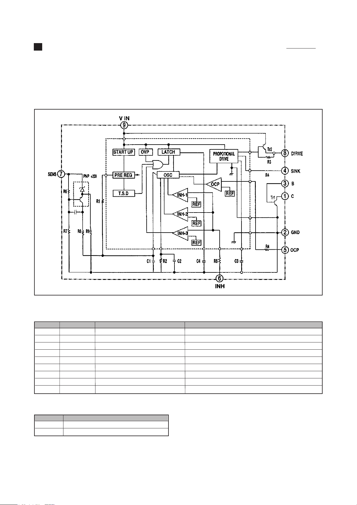
The power IS STR-S5707 has power transistor. oscillator circuit, voltage comparator circuit, thermal protection
circuit, OCP(over current protection)circuit inside.
1. STR-S5707 BLOCK DIAGRAM
2. PIN DESCRIPTION
PIN NO SYMBOL NAME FUNCTION
1 C COLLECTOR POWER TRANSISTOR COLLECTOR
2 GND GROUND GROUND(POWER TRANSISTOR EMITTER)
3 B BASE POWER TRANSISTOR BASE
4 SINK SINK BASE URRENT(Is) INPUT
5 OCP OVER CURRENT PROTECTION OVERCURRENT SENSING SIGNAL INPUT
6 INH INHIBIT/LATCH SYNC, OFF TIME/LATCH CIRCUIT CONTROL INPUT
7 F/B(SENS) FEED BACK(SENSING)INPUT CONSTANT VOLTAGE CONTROL SIGNAL INPUT
8 DRIVE DRIVE BASE DRIVE CURRENT(Id)OUTPUT
9 Vin Vin SUPPLY VOLTAGE FOR CONTROL CIRCUIT
3. OTHER FUNCTION
Symbol Function
OVP Built-in Overvoltage Protection Circuit
TSD Built-in Thermal Shutdown Circuit
14
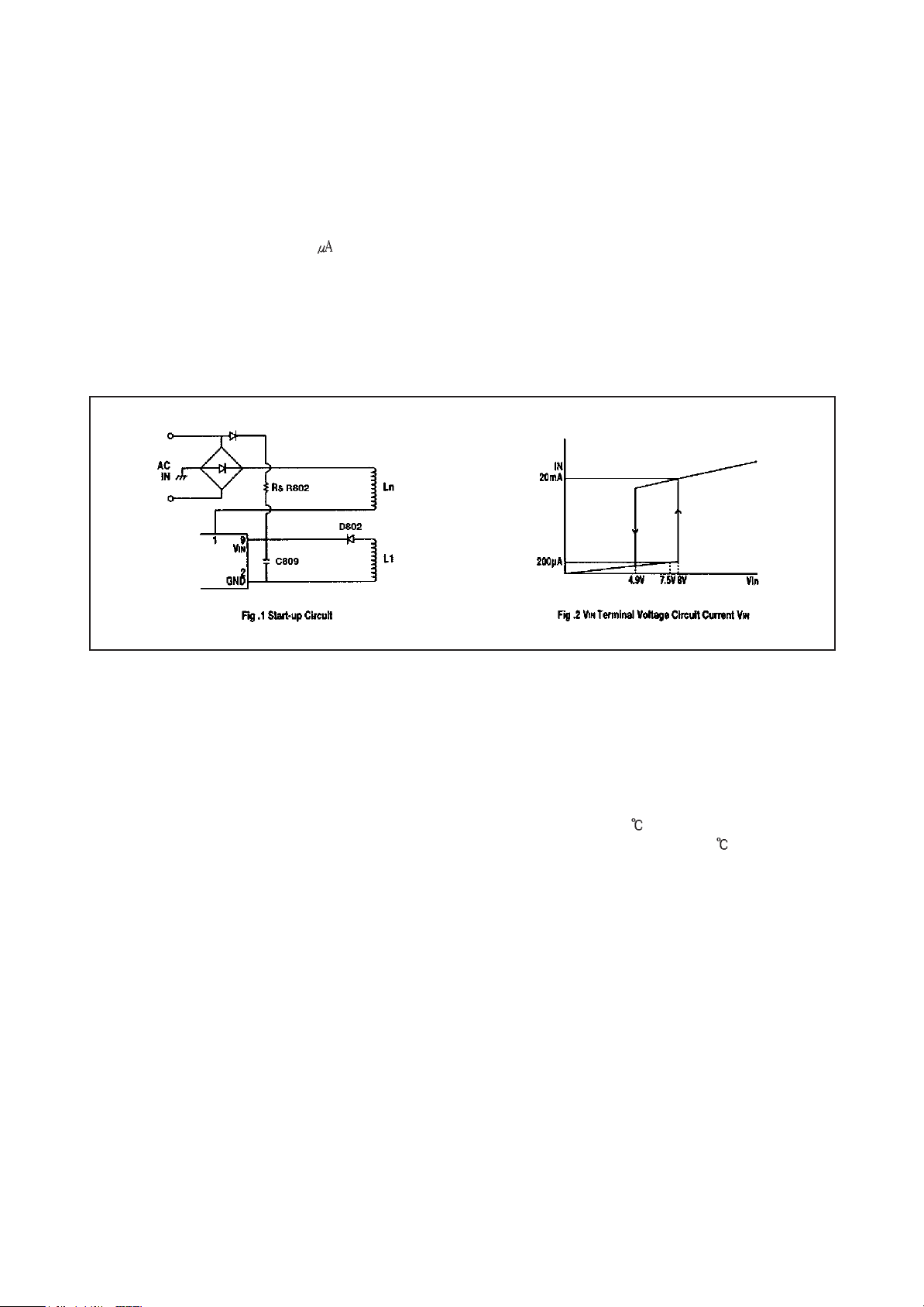
4. EXPLANA TION OF CIRCUIT OPERATION
1) VINterminal, start-up circuit
A Start-up circuit is to start and stop a operation of a control IC by detecting a voltage appearing at a VINterminal(pin-
9).At start up of a power supply, when a voltage at the VINterminal reaches to 8V by charging up C809 by the function
of a start-up resistor, Rs, a control circuit starts operating by the function of the start-up circuit. As shown in Fig. 2, since
a circuit current is suppressed 200 maximum (at VIN= 7.5V) until the control circuit starts its operation.
After the control circuit starts its operation, power source is obtained by smoothing voltage appearing at L1 winding.
Once the control circuit starts operating, as its voltage doesn’t reach the fixed voltage at once, VINterminal voltage
starts dropping. However, as a shut-down voltage is set low(at 4.9V), while VINterminal voltage reaches a shutdown
voltage, L1 winding voltage reaches the fixed voltage earlier so that the control circuit can continue on operating.
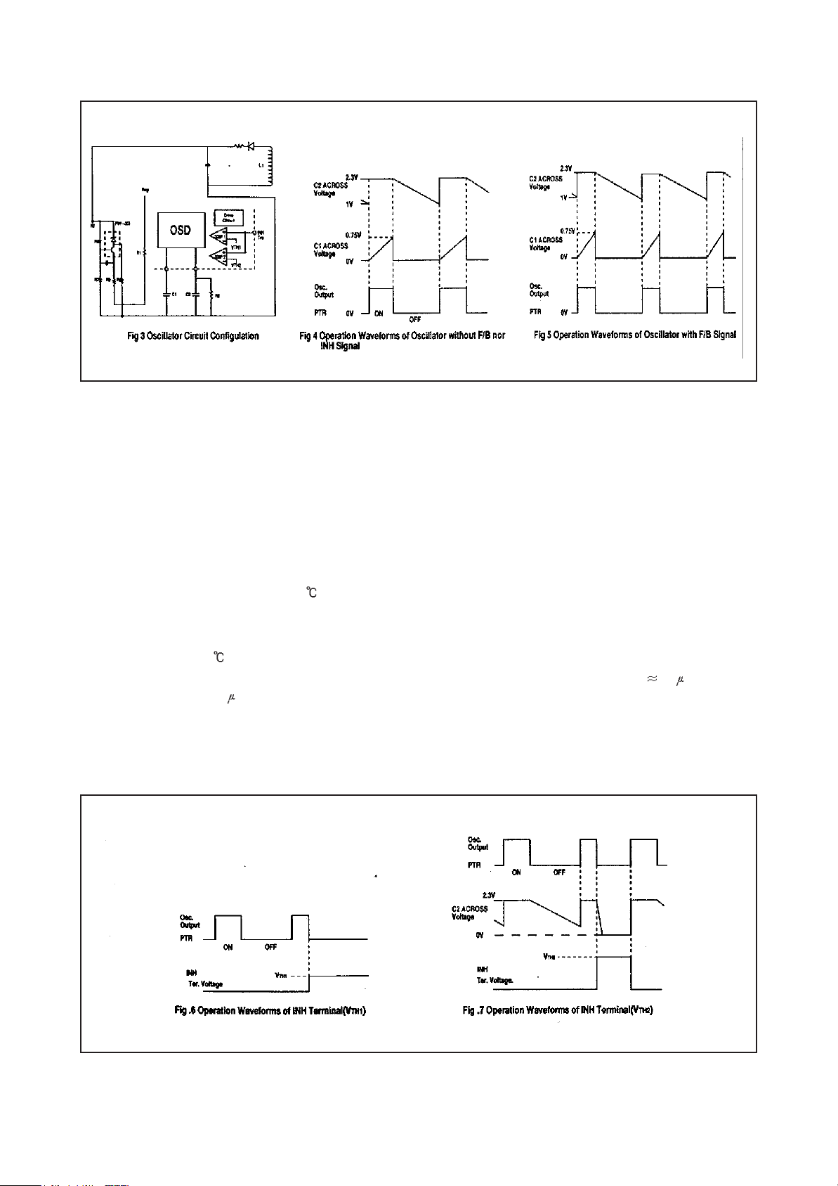
2) Oscillator, F/B terminal voltage (Pin #7)
A oscillator generates pulse signals which turns a power transistor on and off by making use of charge and discharge of
C1 and C2 incorporated in the Hybrid IC.
Constant voltage control of a switch-mode power supply is performed by changing both ON-time and OFF-time except
when the load is light (ex. remote control stand-by mode of TVs).
Fig. 4 shows how the oscillator works when the Hybrid IC independently operates (with no F/B nor INH signals). When
the power thransistor is on, C2 Is charged to the set voltage (approx 2.3V at Ta = 25 ). On the other hand, C1 starts
charging up through R1 from almost OV and the voltage across C1 reaches approx. 0.75V (Tc = 25 ). the output from
the oscillator is reversed and the power transistor turns off. At the same time C1 is quickly discharged by the function of
a internal circuit of the oscillator and the voltage across it decreases to almost OV. When the power transistor turns off,
C2 starts discharging through R2 and the voltage across C2 decreases with the inclination determined by the product of
C2 decreases to about 1V. the output from the oscillator is reversed again and the transistor consequently turns on. The
power transistor continues turning on and off by repeating the above-mentioned operations.
15
As the circuit in Fig. 3 shows, the ON-time is controlled by changing a current charged by C1, which is as the result of
that the detection winding (L1), which detects a change of voltage in a secondary side, connected to the sensing
terminal (Pin No. 7) has the current in accordance with an output signal from an output voltage detection circuit (an error
amplifier) built in. As an AC input voltage to the power supply gets the higher and a load current the smaller, the current
flowing to the SENS terminal gets the larger, and the ON-time gets the shorter.
3) Function of INH terminal (Pin #6), control OFF-time
Signal to the INH terminal is used as inputs to COMP.1 and COMP.2 inside of the control IC.A threshold voltage of
COMP.1 V
is in OFF mode) when a voltage at the INH terminal reaches the V
lower than V
set at 1.5V (Ta = 25 ). When the INH terminal voltage reaches V
TH
is set at 0.75V (Ta = 25 ) and an input signal to a drive circuit becomes almost OV (the power transistor
1
TH
. As long as the INH terminal voltage does not get
1
TH
. the power transistor sustains OFF mode. On the other hand, a threshold voltage of COMP.2 V
1
TH
, an output from COMP.2 reverses and, as a
2
TH
2
, is
result, C2, the OFF-tim of the oscillator which has been determined by the product of C2 and R2 ( 55 sec) can be
quicker up to approx. 2 sec. As long as the INH terminal voltage does not get lower than V
TH
, A Voltage across C2
2
stays at almost 0V and a output from the oscillator keeps the power transistor being on. The relation between the INH
terminal voltage and the function of the oscillator described above is shown in Fig. 6 and FIg. 7
16
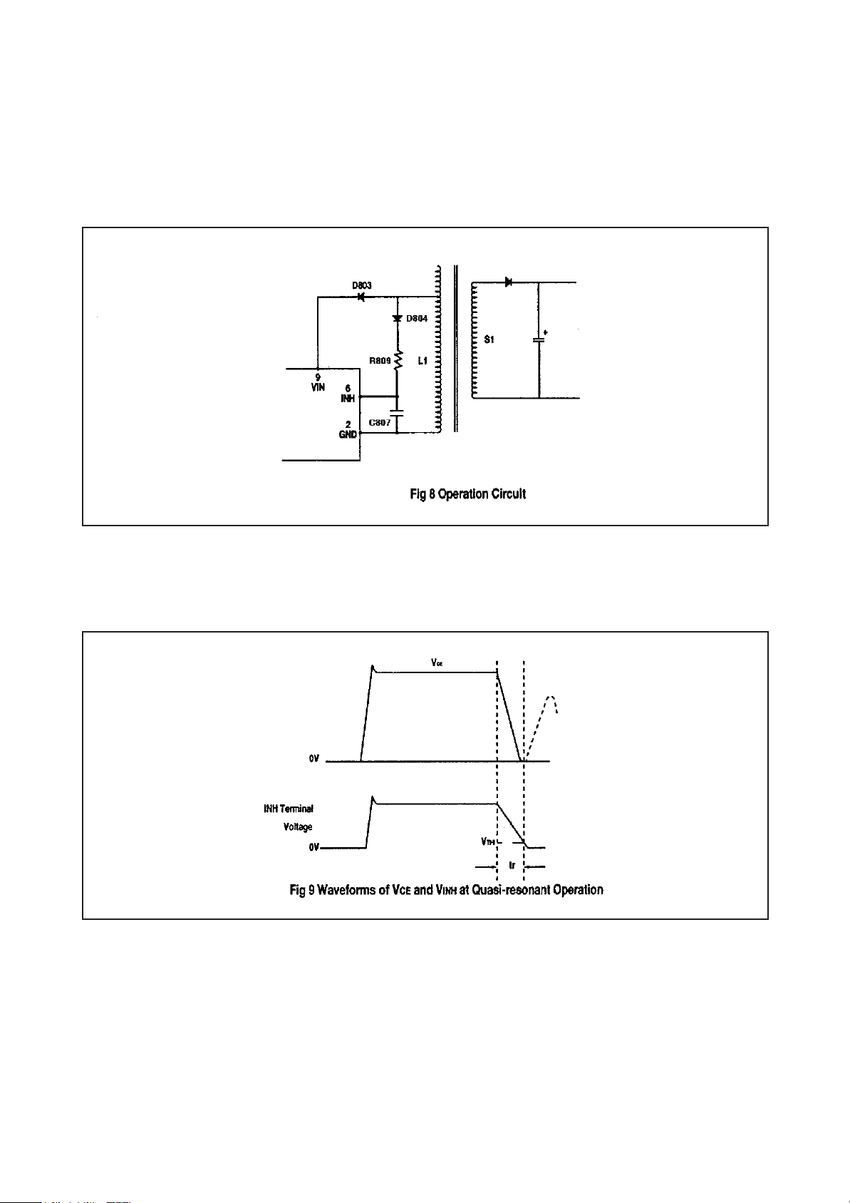
4) Quasi-resonant operation
By inputting a voltage signal which is synchronized with the energy discharge time of a secondary winding of a
transformer to the. INH terminal, quasi-resonant operation can be achieved. As shown in Fig. 8, the voltage of L1
winding which is synchronized. with the energy discharge time of a secondary winding. S1. shall be input to the INH
terminal through D804 and R809. Since V
TH
is set at 1.5V typical, a voltage at the INH terminal. V
2
INH
, shall be set at
Fig. 9 shows waveforms of VCE, Ic and V
INH
of the transistor, voltage across C807 in the oscillator as well as an output
from the oscillator when operating in quasi-resonant mode.
when the power transistor turns off and a voltage than V
and then starts charging again. Even after the discharge of energy of a secondary winding is completed, V
immediately increases. When it gets lower than V
impedance of the IC and C
INH
, has past, the transistor turns on.
TH
is applied to the INH terminal, C807 immediately discharges
2
INH
does not
TH
after the time,tr, which is determined by the production of internal
2
17
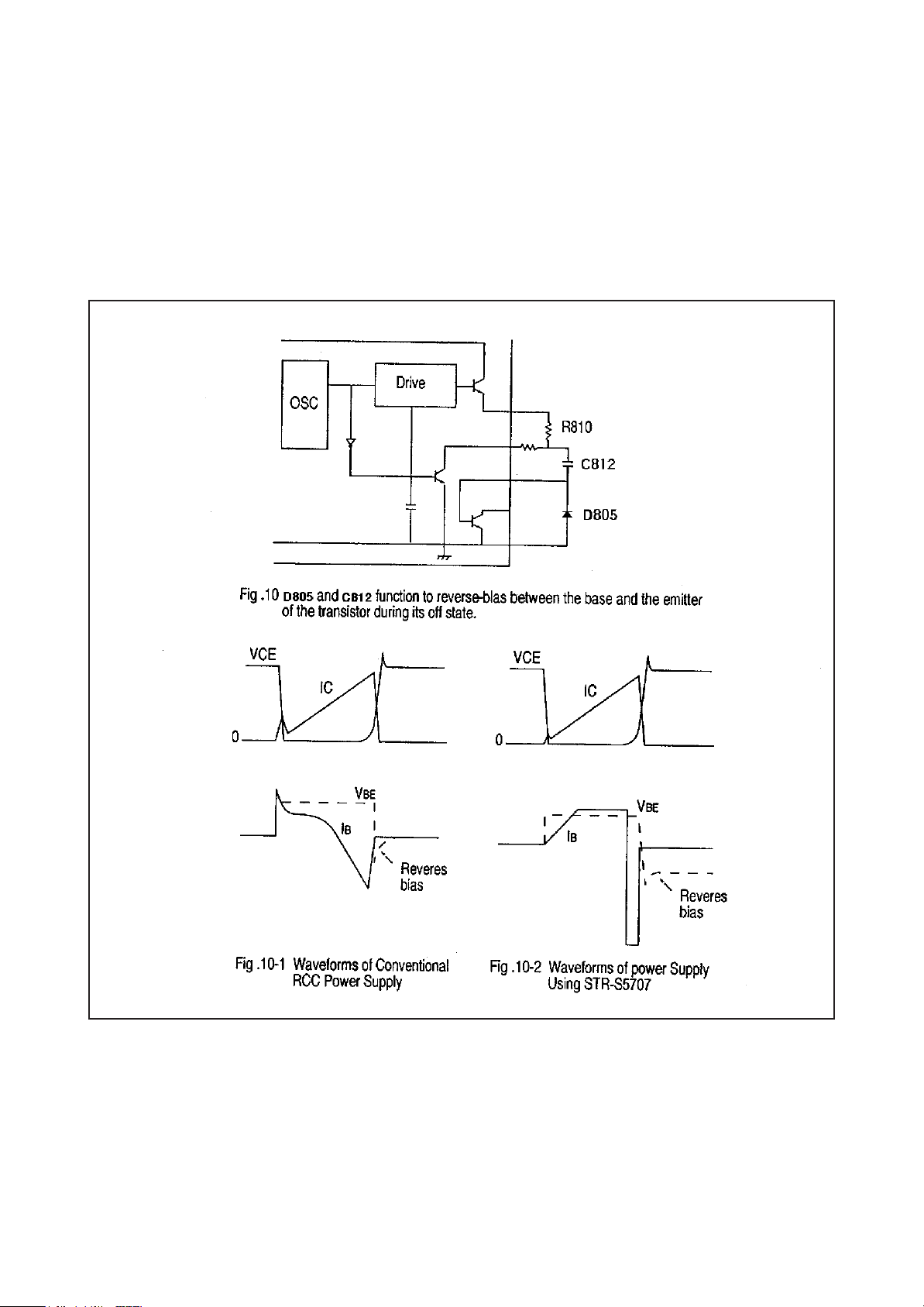
5) Drive circuit
The STR-S5707 applies the proportional drive system in order to minimize turn-on and saturation loss, and storage
time. In the conventional RCC system, turn-on loss and switching noise due to the surge current appearing when the
power transistor turns on are high as because the transistor is driven by the drive current shown in FIg. 10-1. In
addition, since is decreases linearly when the transistor turn off and a peak value of l
long and the V
CE
voltage is high, which results in large turn-off loss. The circuit and the waveforms of the proportional
(
SAT
)
B
is not large, the storage time is
2
drive system which is applied to the STR-S5707 in order to reduce these switching loss and shorten the storage time
are shown in Fig. 10-2 respectively.
18
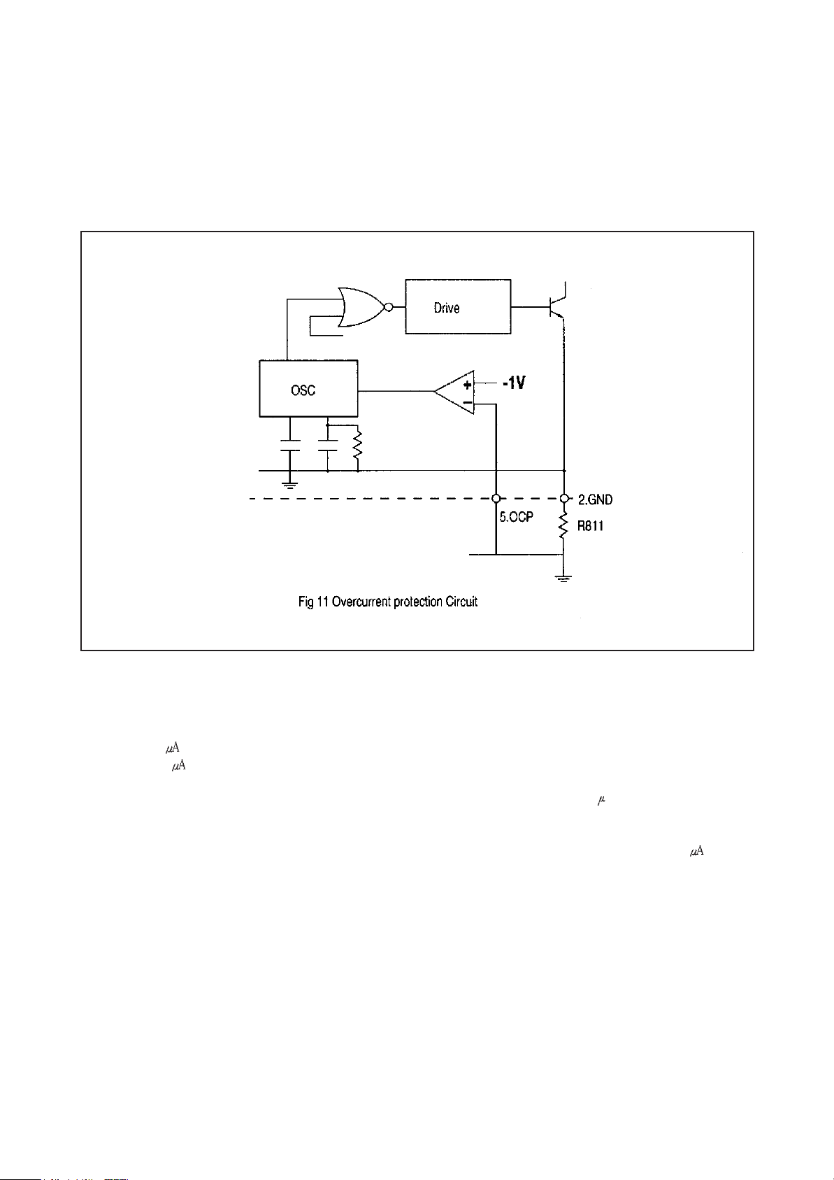
6) OCP (overcurrent protection)function
Overcurrent protection is performed pulse by directly detecting collector current of the power transistor.
Configuration of the OCP circuit is shown in. Detecting voltage is set to-1V below a reference point of GND (ground). In
addition, since the detecting voltage is set by a comparator, very stable characteristics against temperature is achieved
and drift of the deteting voltage against temperature change is almost OV.
7) Latch circuit
It is a circuit which sustains an output from the oscillator low and stops operation of the power supply when overvoltage
protection (OVP) circuit and thermal shutdown (TSD) circuit are in operation. As the sustaining current of the latch
circuit is 500 maximum when VINterminal voltage is 4V. the power supply circuit sustains the off state as long as
current of 500 maximum flows to VINterminal from a start-up resistor. In order to prevent a malfunction to be caused
by a noise and so on, delay time is provided by C1 incorporated in the IC and, therefore, the latch circuit operates when
the OVP of TSD circuit is in operation, of an external signal input is provided. for about 10 sec or longer. In addition,
even after the latch circuit start operating, the constant voltage regulator (Reg) circuit is in operation and the circuit
current is at high level. As a result. VINterminal voltage rapidly decreases. When V
than the shutdown voltage, V
reaches the ON-state voltage. VIN(ON), (8V typical), V
IN
(OFF), (4.9V typical), it starts in-creasing as the circuit current is below 500 . When it
terminal voltage starts decreasing because the circuit current
IN
terminal voltage becomes lower
IN
increases again.
19
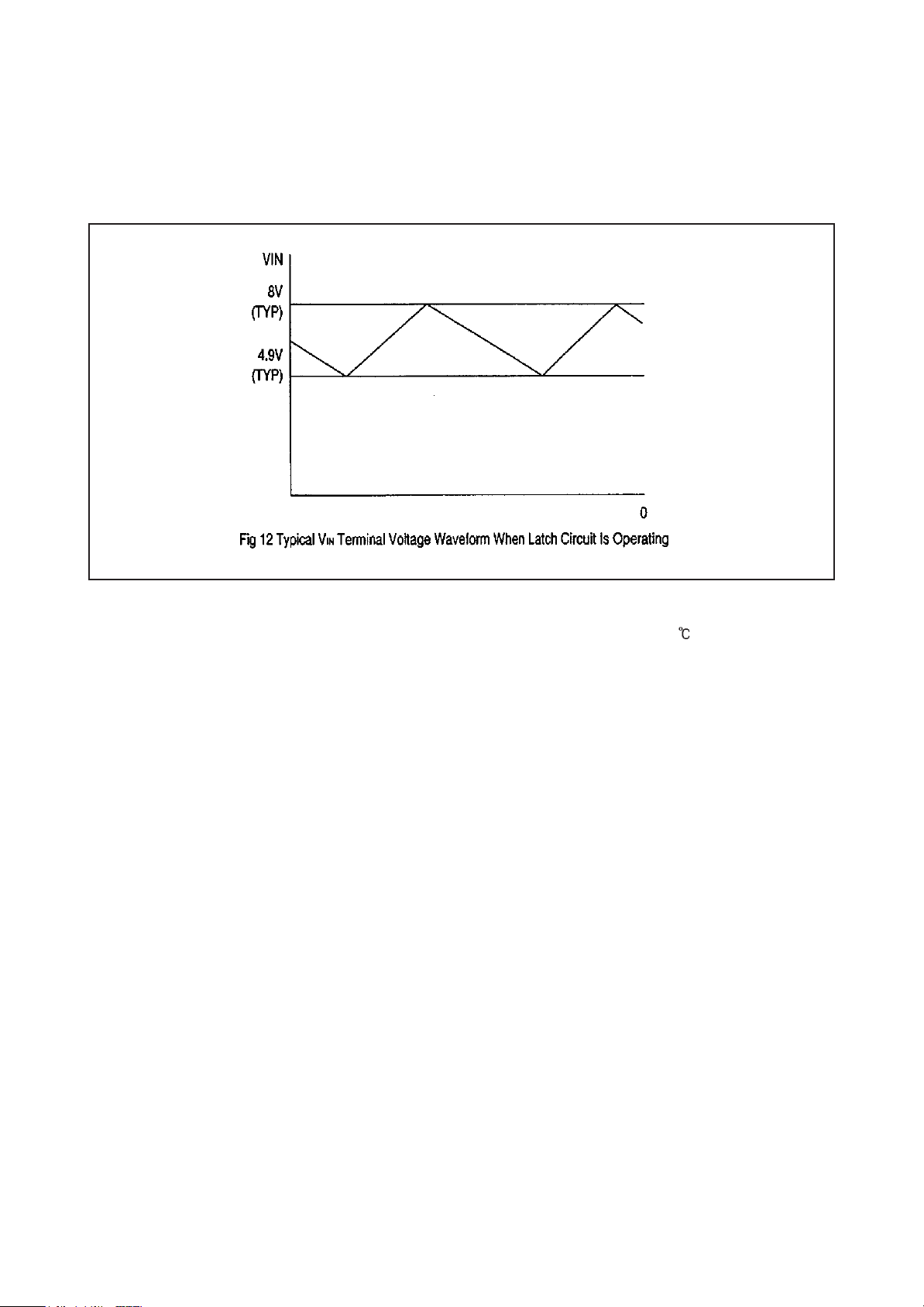
when the latch circuit is on. VINterminal voltage increases and decreases with-in the range from 4.9V typical to 8V
typical and is prevented from abnormally rising. Fig. 12 shows an example of VINterminal voltage waveform.
Cancellation of the latch-is done by decreasing VINterminal voltage below 3.3V. The power supply can be restarted
disconnecting an AC input to the power supply once.
8) Thermal shutdown, circuit
It is a circuit to trigger the latch circuit when the frame temperature of the IC exceeds 150 (typical). Although the
temperature is actually sensed at the control chip. lt works against overheating of the power transistor as the power
transistor and the control IC are mounted on the same lead frame.
9) Overvoltage protection circuit
lt is a circuit to trigger the latch circuit when Vin terminal voltage exceeds 11V (typical). Although it basically functions as
protection of Vin terminal against overvoltage, since Vin terminal is usually supplied from the drive winding of the
transformer and the voltage is proportional to the output voltage, it also functions against the overvoltage of secondary
output which causes when the control circuit opens or in some other events.
20
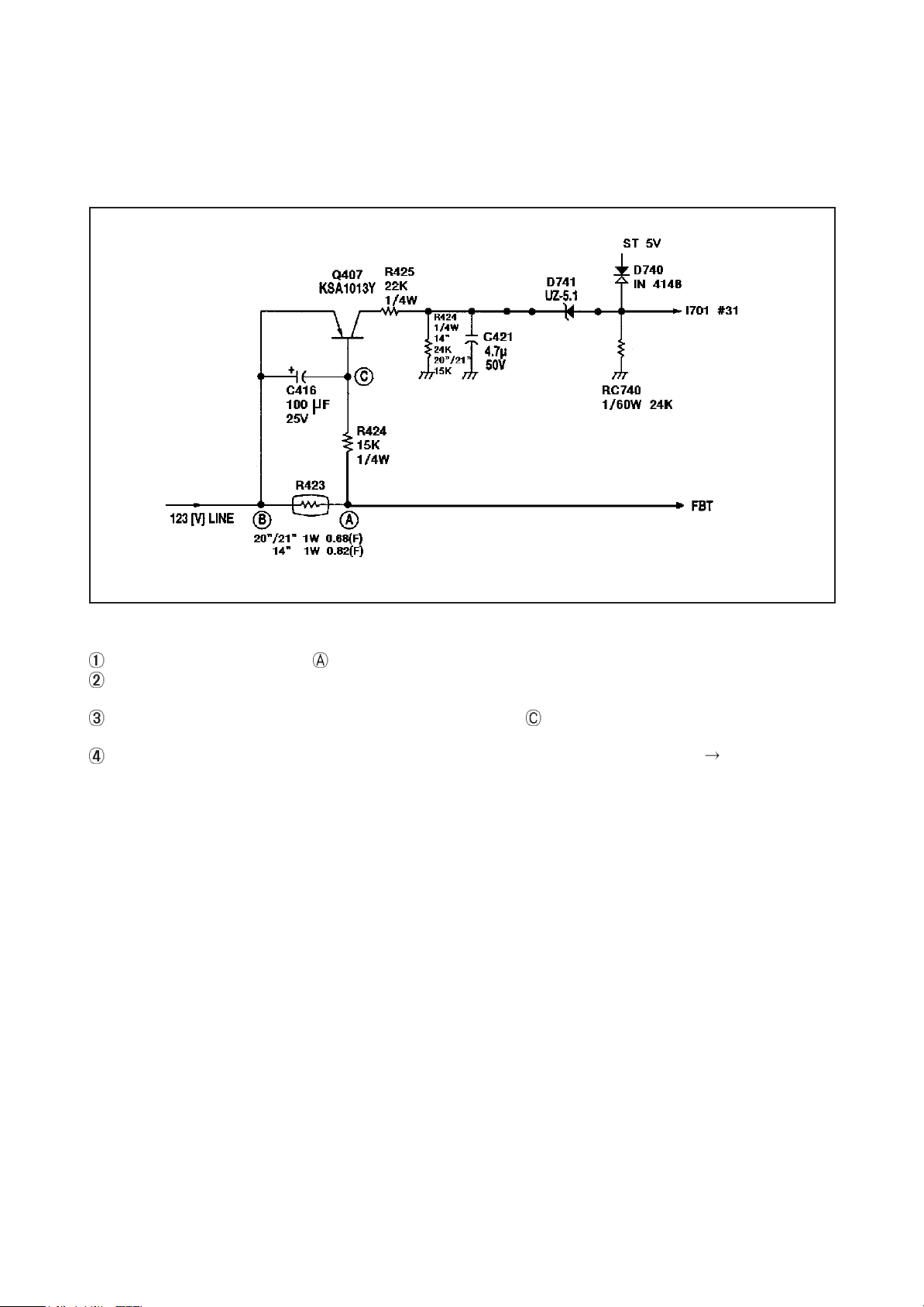
5. OCP (OVER CURRENT PROTECTION) CIRCUIT
This circuit is designed to protect the circuit from over current due to overload occurred at the rear of 123[V] line
1) CONFIGURATION OF OCP CIRCUIT
2) EXPLANATION OF THE OPERATION
There is very little voltage drop at R423 of 123[V] line.
In case that the overload occurs at the rear of 123[V] line, the increase of the voltage drop at R423 bring down the base
voltage of the Q407 os as to drive the Q407
Because of the overload at the rear of the R423, the voltage of the point decreases. And this makes Q407 turn on
so that a voltage is applied to the #31 of l701.
In case that OCP operates by the #31 of the l1701, the set is protected by power off (#42 of l1701 LOW).
21
 Loading...