


DAEWOO ACP-0106A, CDP-0105A, ACP-5010RDS, ACP-5010RC, ACP-5010C Service Manual
...
S/M No : ACP0108EF0
Service Manual
Car Audio
MODEL : ACP-0108 Series
 0106Series
  5010Series
 ACP-0106A
  CDP-0105A
 ACP-5010RDS
 ACP-5010RC
 ACP-5010C
 ACP-5010
  AKP-5010RDS
4-Channel high Power (40W x 4Ch)  Electronic Tuning
 Electronic Volume/Bass/Treble/Balance/Fader Control
 42 Memory Capability (18FM+12MW+12LW)
 Local/DX Switch
 Loudness & Mute Control
 Compact Disc Player
 Detachable Face for Anti-Theft
 10 CD-changer control(Option)
  Telephone Mute Control
DAEWOO ELECTRONICS CO., LTD
http://svc.dwe.co.kr |
Mar. 2001 |

TABLE OF CONTENTS
1. |
PRODUCT SPECIFICATIONS .................................................. |
1 |
2. |
LINE DRAWING ........................................................................ |
2 |
3. |
EMERGENCY TROUBLE SHOOT ............................................ |
3 |
4. |
ADJUSTMENTS ........................................................................ |
6 |
5. |
SCHEMATIC DIAGRAM .......................................................... |
11 |
6. |
PARTS LOCATION ON P.C.BOARD ...................................... |
12 |
7. |
OVERALL EXPLODED VIEW & PARTS LIST ....................... |
15 |
8. |
DECK MECHANISM EXPLODED VIEW & PARTS LIST ....... |
16 |
9. |
ELECTRICAL PARTS LIST........................................................ |
20 |
10. |
FUNCTION OF MICOM IC ..................................................... |
24 |
11. IC BLOCK DIAGRAM ............................................................. |
30 |
|
12. |
LIQUID CRYSTAL DISPLAY .................................................. |
34 |
13. |
OUTPUT CONNECTION DESCRIPTIONS ............................ |
35 |

1. PRODUCT SPECIFICATIONS
 AUDIO SECTION
Maximum output power |
: 40watts per channel into 4 ohms. |
||||||
Load impedance |
: 4 ohms or 8 ohms |
||||||
Total harmonic distortion |
: Less than 10% at 12 watts |
||||||
Frequency response |
: 100Hz( |
+ |
3dB), 10kHz(-5 |
+ |
3dB) |
||
|
|||||||
|
|
||||||
Control Bass/Treble |
: 10 |
+ |
3dB at 100Hz/10kHz |
||||
|
|||||||
 CD PLAYER SECTION
System |
: 2-track / 2-channel system |
|
Total harmonic distortion |
: 0.35%max. (WRMS) |
|
Signal to noise ratio(network) |
: 63Hz ~ 10kHz |
(+3dB) normal (LH)tape |
|
||
Wow and flutter Below measurable limit |
||
Laser Diode Properties |
: Meterial |
|
|
Ga AIAS |
|
|
Wave length |
|
|
760-800 mm |
|
|
Emission Duration |
|
|
Continuous |
|
|
Laser out-put Power |
|
|
Less than 44.6 W |
|
 TUNER SECTION
(FM) Tuning range |
: 87.5 to 108MHz |
Sensitivity |
: 10dBuV |
Stereo separation |
: 30dB |
Signal to noise ratio |
: 55dB |
Frequency range |
: 87.5 ~ 108MH |
|
: 522 to 1620KHz at Europe |
(MW) Tuning range |
: 530 to 1710kHz at U.S.A |
Sensitivity |
: 28dBuV |
Signal to noise ratio |
: 50dB |
Frequency range |
: 522 ~ 1620KHz |
Channel space |
: 9KHz (or 10KHz at U.S.A) |
(LW) Tuning range |
: 144 to 288KHz |
Usable Sensitivity |
: 40dBuV |
 GENERAL
Power requirements |
: DC 13.8V (10.8 ~15.6V allowable) |
|
Negative ground |
Spdaker impedance |
: 4 or 8 ohm |
Output power |
: Maximum 40Wx4Ch. |
Current consumption |
: 10A |
Dimension (W x H x D) |
: 178 x 50 x 156 mm |
Chassis size |
: 195 x 64 x 14.6 mm |
Weight(Net) |
: 1.75Kg |
Design and specifications are subject to changes for improvements without notice.
1
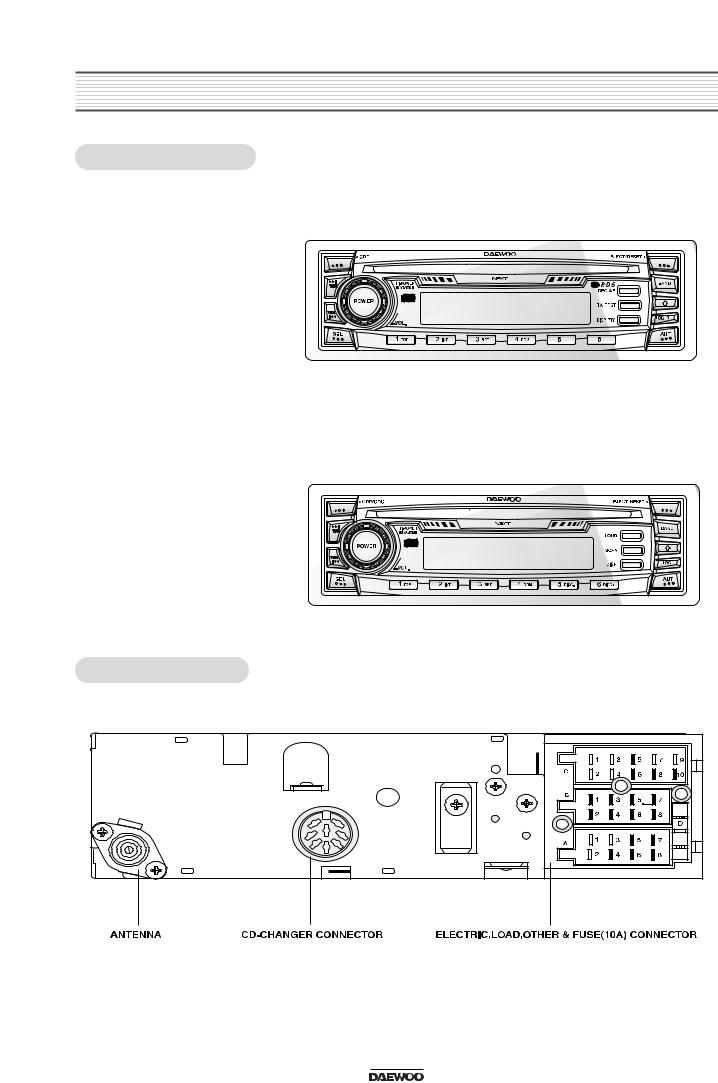
2. LINE DRAWING
2-1. FRONT SIDE
 ACP-0108RDS Serise
-RDS Function
-Compact Disc Player
- 4-Channel high Power (40W x 4Ch) - Electronic Tuning
- Electronic Volume /Bass /Treble /Balance /Fader Control
- 42 Memory Capability (18FM+12MW+12LW) - Local/DX Switch
- Loudness & Mute Control
-Detachable Face for Anti-Theft
-10 CD-changer control(Option)
- Telephone Mute Control |
*ACP-5010RDS, 5010RC *AKP-5010RDS |
 ACP-0108 BASIC Series
-Basic Function
-Compact Disc Player
-4-Channel high Power (40W x 4Ch)
-Electronic Tuning
-Electronic Volume /Bass /Treble /Balance /Fader Control
-42 Memory Capability (18FM+12MW+12LW)
-Local/DX Switch
-Loudness & Mute Control
-Detachable Face for Anti-Theft
-10 CD-changer control(Option)
-Telephone Mute Control
2-2. REAR SIDE
*ACP-5010C, 5010 *CDP-0105A
*ACP-0106A
2
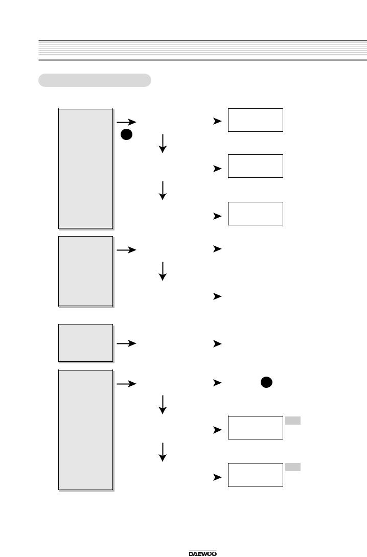
3. EMERGENCY TROUBLE SHOOT
3-1. General Function
Yes
No sound from
speakers
A
Yes
Different each channel have output level (Front, Rear, Left, Right)
Treble or Bass
Yes
is low unusually
Yes
L.C.D or Lamp is not turned off.
|
Output connector |
|
Yes |
|
|
||
|
is missing |
|
|
|
|
|
|
|
|
|
|
|
|
|
|
|
Output connector |
|
Yes |
|
is inferior goods |
|
|
|
|
|
|
|
|
|
|
|
No |
|
|
|
|
|
|
|
Power IC, Output |
|
Yes |
|
Socket is inferior |
|
|
|
|
|
|
|
goods |
|
|
|
|
|
|
|
Balance of front |
|
Yes |
|
and rear is in one |
|
|
|
side |
|
|
|
No |
|
|
|
|
|
|
|
Balance of Left, |
|
Yes |
|
Right is in one |
|
|
|
side. |
|
|
|
|
|
|
|
Balance of Treble |
|
Yes |
|
or Bass is in one |
|
|
|
|
|
|
|
side. |
|
|
|
|
|
Yes |
|
Power is not |
|
|
|
supplied |
|
|
|
|
|
|
|
|
|
|
|
No |
|
|
|
|
|
|
|
Output voltage of |
|
Yes |
|
power IC is little. |
|
|
|
|
|
|
|
|
|
|
|
No |
|
|
|
|
|
|
|
LCD or Lamp is |
|
Yes |
|
inferior goods. |
|
|
|
|
|
|
|
|
|
|
|
|
|
|
Put exactly output connector in.
Change connector superior
Change IC, Output
superior
Re-adjust Balance |
|
Ref. |
Balance = Center |
of front, rear |
|
|
Front / Rear |
|
|
|
|
|
|
|
|
Re-adjust Balance |
|
Ref. |
Balance = Center |
|
|
Left / Right |
|
of Left, Right |
|
|
|
|
|
|
|
|
|
|
|
Re-adjust Balance |
|
Ref. |
Balance = Center |
|
|
Treble / Bass |
|
of Treble or Bass |
|
|
|
|
|
|
|
|
|
|
|
Return to A
Change Regulator Ref. Regulator IC output
IC and check Voltage = V output voltage.
Change LCD or Ref. Electrical Parts List
Lamp to superior L.C.D., Lamp goods.
3
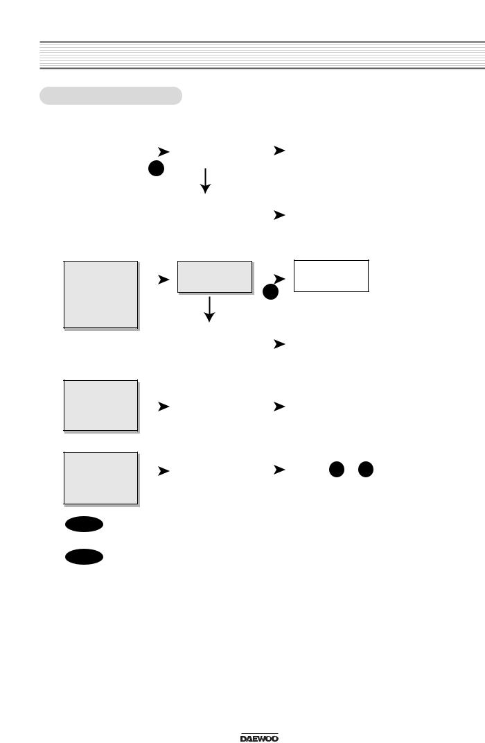
EMERGENCY TROUBLE SHOOT
3-2. Tuner Function
|
|
Yes |
No selected the |
|
Yes |
Select exactly |
|
|
|
||
Hearing noise |
|
|
broadcasting |
|
|
|
|||||
|
|
|
station |
|
|
|
|
|
|
||
|
|
|
|
|
|
frequency. |
|
|
|
||
only |
|
|
|
|
|
|
|
|
|
|
|
|
|
A |
|
|
|
|
|
|
|
CAT-7 |
|
|
|
|
|
|
|
|
|
|
|
|
|
|
|
|
|
Tuner Module is |
|
|
|
Change tuner |
|
Ref. |
|
|
|
|
|
|
|
|
module to |
|
|
Adjustments/Tuner |
|
|
|
|
|
inferior goods. |
|
|
|
|
|
||
|
|
|
|
|
|
|
superior goods. |
|
|
|
|
|
|
|
|
|
|
|
|
|
|
|
|
|
|
|
|
|
|
|
|
|
|
|
|
Extreme noise in broadcast
Weak separation of FM stereo
Station in
.
Yes |
Weak frequency |
|
Change to goods of |
|
|
|
area caused by |
|
R.D.S function. |
|
|
|
||
B
|
|
|
No |
|
|
|
|
|
|
|
|
|
|
|
|
|
|
|
|
|
|
|
|
|
Antenna |
|
Yes |
|
Put exactly |
|
|
|
|
|
|
connector is |
|
|
|
antenna connector |
|
|
|
|
|
|
missing |
|
|
|
in his jack |
|
|
|
|
|
|
|
|
|
|
|
|
Function of auto- |
|
Yes |
|
Weak frequency |
|
Yes |
|
Switch |
|
Ref. |
||
|
|
|
switch noise |
|||||||
|
|
|
area of FM, MW |
|
|
|
automatically to |
|
|
|
|
|
|
|
|
|
mono mode in |
|
|
reduction |
|
|
|
|
|
|
|
|
weak frequency |
|
|
|
Yes |
|
|
|
Yes |
|
area |
|
|
|
|
|
|
|
|
|
|
|
|
|||
|
No selected the |
|
|
B |
|
|
||||
|
|
|
local stations. |
|
|
|
|
|
||
|
|
|
|
|
|
|
||||
|
|
|
|
|
|
|
|
|
|
|
|
|
|
|
|
|
|
|
|
|
|
R1 |
In case of located Glass Antenna, check if heat wire is cut or not in rear window. |
R2 |
Check Antenna connector part. |
4
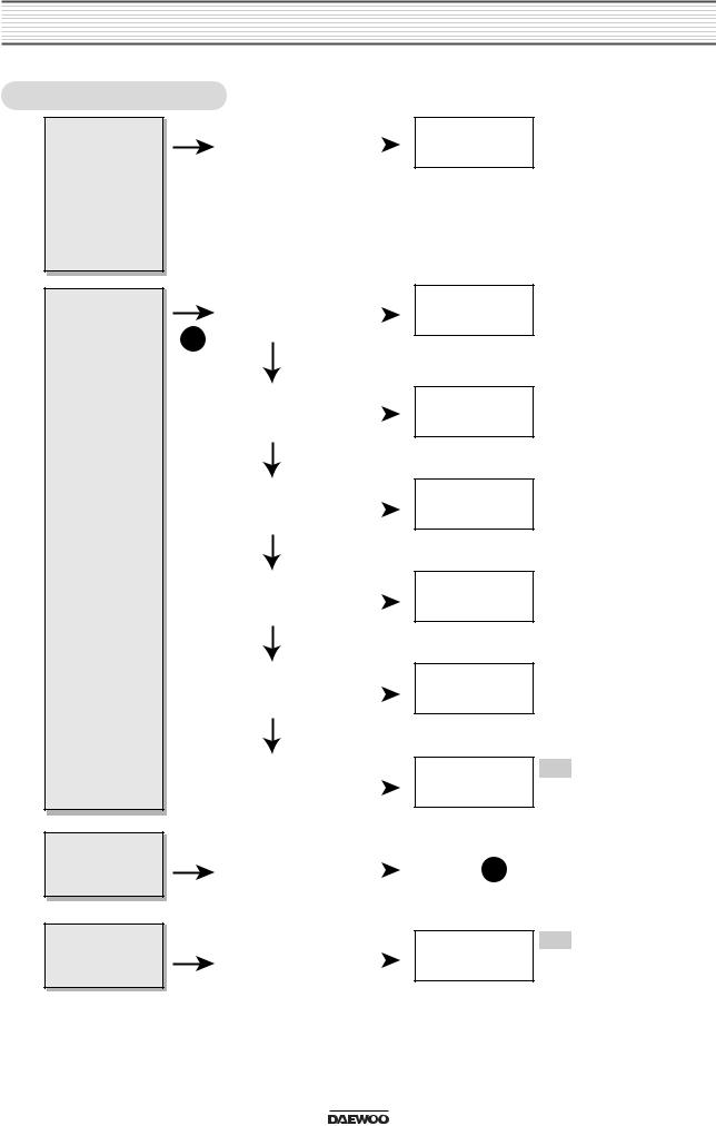
EMERGENCY TROUBLE SHOOT
3-3. CD Function
under eject
|
There is Disc in |
|
Yes |
|
|
||
|
the slot |
|
|
|
|
|
|
|
|
|
|
|
|
|
|
|
Disc is inferior |
|
Yes |
|
|
||
|
goods |
|
|
|
|
Yes |
|
|
|
|
|
|
|
|
|
|
disc was inserted |
|
|
|
upside down |
|
|
|
|
|
|
|
|
|
|
|
No |
|
|
|
|
|
Yes |
|
Disc is dirty |
|
|
|
|
|
|
|
|
|
|
|
No |
|
|
|
|
|
|
|
Selected PAUSE |
|
Yes |
|
function |
|
|
|
|
|
|
|
|
|
|
|
No |
|
|
|
|
|
|
|
Selected MUTE |
|
Yes |
|
function |
|
|
|
|
|
|
|
|
|
|
|
No |
|
|
|
|
|
|
|
Mechanism is |
|
Yes |
|
inferior goods |
|
|
|
|
|
|
|
|
|
|
|
|
|
|
|
Inspect disc for |
|
Yes |
|
scratches. |
|
|
|
|
|
|
|
|
|
|
|
|
|
|
|
It is normal for |
|
Yes |
|
CD-Deck or the |
|
|
|
|
|
|
|
slot |
|
|
|
|
|
|
Take out Disc from the slot
Use only superior disc
Insert CD with label side down
Wipe with cleaning cloth
Release PAUSE function
Release function
Change
superior
Ref. Point A
Turn power on again after turn off.
Ref. DWEC CD Mecha
DCM-200/201
Ref. Power Off/On
Hard Reset
5
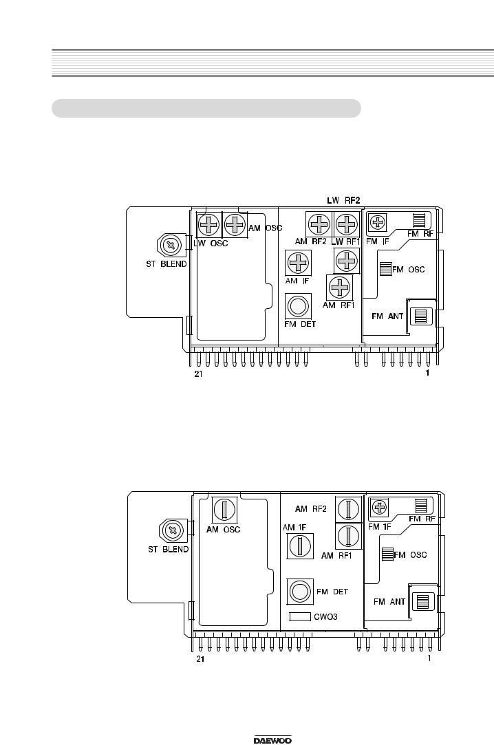
4. ADJUSTMENTS
4-1. TUNER MODULE ADJUSTMENT LOCATIONS
 CAT-7 (3 Band)
 CAT-6 (2 Band)
6
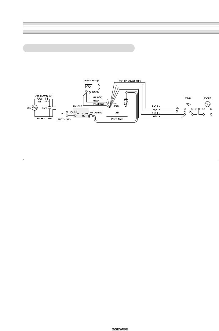
ADJUSTMENTS
4-2. MW / LW ADJUSTMENT METHOD
|
|
|
|
|
|
|
|
|
|
|
|
|
|
|
|
|
|
|
|
|
|
|
|
|
|
|
|
|
|
|
|
|
|
|
|
|
|
|
|
|
|
|
|
|
|
|
|
|
|
|
|
|
|
|
|
|
|
|
|
|
|
|
|
|
|
|
|
|
|
|
|
|
|
|
|
|
|
|
|
|
|
|
|
|
|
|
|
|
|
|
|
|
|
|
|
|
|
|
|
|
|
|
|
|
|
|
|
|
|
|
|
|
|
|
|
|
|
|
|
|
|
|
|
|
|
|
|
|
|
|
|
|
|
|
|
|
|
|
|
|
|
|
|
|
|
|
|
|
|
|
|
|
|
|
|
|
|
|
|
|
|
|
|
|
|
|
|
|
|
|
|
|
|
|
|
|
|
|
|
|
|
|
|
|
|
|
|
|
|
|
|
|
|
|
|
|
|
|
|
|
|
|
|
|
|
|
|
|
|
|
|
|
|
|
|
|
|
|
|
|
|
|
|
|
|
|
|
|
|
|
|
|
|
|
|
|
|
|
|
|
|
|
|
|
|
|
|
|
|
|
|
|
|
|
|
|
|
|
|
|
|
|
|
|
|
|
|
|
|
|
|
|
|
|
|
|
|
|
|
|
|
|
|
|
|
|
|
|
|
|
|
|
|
|
|
|
|
|
|
|
|
|
|
|
|
|
|
|
|
|
|
|
|
|
|
|
|
|
|
|
|
|
|
|
|
|
|
|
|
|
|
|
|
|
|
|
|
STEP |
ALIGNMENT |
|
TUNING |
|
|
|
TEST |
|
|
SSG |
ALIGNMENT |
INDICATOR |
|||||||||||||
|
|
|
POSITION |
FREQUENCY |
|||||||||||||||||||||
|
|
|
|
|
|
|
|
|
|
|
|
|
|
|
|
|
|
|
|||||||
|
|
|
|
|
|
|
|
|
|
|
|
|
|
|
|
|
|
|
|
|
|
|
|
|
|
|
Band Covering |
|
522 KHz |
|
|
V.T point of |
|
522 KHz |
AMOSC |
MAXIMUM |
|||||||||||||||
|
Range |
|
|
|
|
|
|
|
|
|
|
|
|
|
|
|
|
|
|
||||||
|
|
|
|
|
|
|
|
|
|
|
AM Board |
|
|
|
|
|
|
|
|
|
|||||
|
1620 KHz |
|
|
|
|
1620 KHz |
- |
|
|
|
|
|
|||||||||||||
|
|
|
|
|
|
|
|
|
|
|
|
|
|||||||||||||
|
|
|
|
|
|
|
|
|
|
|
|
|
7.6V |
||||||||||||
MW |
|
|
|
|
|
|
|
|
|
|
|
|
|
|
|
|
|
|
|
|
|
|
|
|
|
IF |
|
522 KHz |
|
|
|
Output |
|
450 KHz |
AMIF |
MAXIMUM |
|||||||||||||||
|
|
|
|
|
|
||||||||||||||||||||
|
|
|
|
|
|
|
|
|
|
|
|
|
|
|
|
|
|
|
|
|
|
|
|
|
|
|
|
|
|
|
603 KHz |
|
|
|
Output |
|
603 KHz |
AMRF1 |
MAXIMUM |
||||||||||||
|
TRACKING |
|
|
|
|
|
AMRF2 |
||||||||||||||||||
|
|
|
|
|
|
|
|
|
|
|
|
|
|
|
|
|
|
|
|
|
|
||||
|
|
|
|
|
|
|
|
|
|
|
|
|
|
|
|
|
|
|
|
|
|
|
|
|
|
|
|
|
|
1404 KHz |
|
|
|
Output |
|
1404 KHz |
AMRF1 |
MAXIMUM |
|||||||||||||
|
|
|
|
|
|
|
|
AMRF2 |
|||||||||||||||||
|
|
|
|
|
|
|
|
|
|
|
|
|
|
|
|
|
|
|
|
|
|
|
|
|
|
|
|
|
|
|
|
|
|
|
|
|
|
|
|
|
|
|
|
|
|
|
|
|
|
|
|
|
Band Covering |
|
144 KHz |
- |
|
|
144 KHz |
LWOSC |
MAXIMUM |
||||||||||||||||
LW |
Range |
|
|
|
|
|
|
|
|
|
|
|
|
|
|
|
|
|
|
|
|
|
|
||
TRACKING |
220 KHz |
|
|
|
Output |
|
220 KHz |
LMRF1 |
MAXIMUM |
||||||||||||||||
|
|
|
|
|
|||||||||||||||||||||
|
|
|
|
|
LMRF2 |
||||||||||||||||||||
|
|
|
|
|
|
|
|
|
|
|
|
|
|
|
|
|
|
|
|
|
|
|
|
|
|
|
|
|
|
|
|
|
|
|
|
|
|
|
|
|
|
|
|
|
|
|
|
|
|
|
|
7
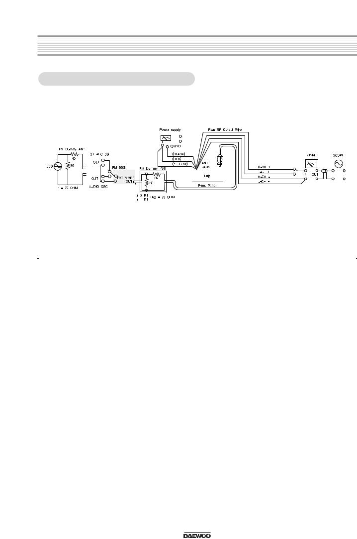
ADJUSTMENTS
4-3. FM ADJUSTMENT METHOD
|
|
|
|
|
|
|
|
|
|
|
|
|
|
|
|
|
|
|
|
|
|
|
|
|
|
|
|
|
|
|
|
|
|
|
|
|
|
|
|
|
|
|
|
|
|
|
|
|
|
|
|
|
|
|
|
|
|
|
|
|
|
|
|
|
|
|
|
|
|
|
|
|
|
|
|
|
|
|
|
|
|
|
|
|
|
|
|
|
|
|
|
|
|
|
|
|
|
|
|
|
|
|
|
|
|
|
|
|
|
|
|
|
|
|
|
|
|
|
|
|
|
|
|
|
|
|
|
|
|
|
|
|
|
|
|
|
|
|
|
|
|
|
|
|
|
|
|
|
|
|
|
|
|
|
|
|
|
|
|
|
|
|
|
|
|
|
|
|
|
|
|
|
|
|
|
|
|
|
|
|
|
|
|
|
|
|
|
|
|
|
|
|
|
|
|
|
|
|
|
|
|
|
|
|
|
|
|
|
|
|
|
|
|
|
|
|
|
|
|
|
|
|
|
|
|
|
|
|
|
|
|
|
|
|
|
|
|
|
|
|
|
|
|
|
|
|
|
|
|
|
|
|
|
|
|
|
|
|
|
|
|
|
|
|
|
|
|
|
|
|
|
|
|
|
|
|
|
|
|
|
|
|
|
|
|
|
|
|
|
|
|
|
|
|
|
|
|
|
|
|
|
|
|
|
|
|
|
|
|
|
|
|
|
|
|
|
|
|
|
|
|
|
|
|
|
|
|
|
|
|
|
|
|
|
|
|
|
|
|
|
|
|
|
|
|
|
|
|
|
|
|
|
|
|
|
|
|
|
|
|
|
|
|
|
|
|
|
|
|
|
|
|
|
|
|
|
|
STEP |
SUBJECT |
|
|
FEED SIGNAL |
|
MEASURE |
ADJUST |
|
ADJUSTMENT |
|||||||||||||||||
|
FROM |
|
|
|
TO |
|
OUTPUT |
POINT |
|
|||||||||||||||||
|
|
|
|
|
|
|
|
|
|
|
|
|
|
|
||||||||||||
|
|
|
|
|
|
|
|
|
|
|
|
|
|
|
|
|
|
|
|
|
|
|
|
|
|
|
|
|
|
|
98.1 MHz, ANT |
|
|
|
|
|
|
The voltage |
|
|
|
|
|
|
|
||||||||
1 |
IF adjust |
input 60dBu, 1kHz |
|
|
ANT jack |
FM DET |
Adjust for 0V |
|||||||||||||||||||
(30% MOD) FM |
|
|
and GND |
between CW03 |
0.05V |
|||||||||||||||||||||
|
|
|
|
|
|
|
||||||||||||||||||||
|
|
|
|
SSG |
|
|
|
|
|
|
|
|
|
|
|
|
|
|
|
|
||||||
|
|
|
|
|
|
|
|
|
|
|
|
|
|
|
|
|
|
|
|
|
|
|
|
|
|
|
|
MPX IC |
98.1 MHz, ANT |
|
|
|
|
|
|
L or R CH SP. |
|
|
|
|
|
|
|
||||||||||
2 |
input 40dBu, 1kHz |
|
|
ANT jack |
ST |
|
L, R separation |
|||||||||||||||||||
Separation |
(L+R=45% |
|
|
|
output wire |
|
||||||||||||||||||||
|
|
and GND |
|
BLEND |
|
8dB |
||||||||||||||||||||
|
Control |
L-R=45% |
|
|
VTVM and Scope |
|
||||||||||||||||||||
|
|
|
|
|
|
|
|
|
|
|
|
|
|
|||||||||||||
|
|
|
|
PILOT=10% MOD) |
|
|
|
|
|
|
|
|
|
|
|
|
|
|
|
|
||||||
|
|
|
|
|
|
|
|
|
|
|
|
|
|
|
|
|
|
|
|
|
|
|
|
|
|
|
8
ADJUSTMENTS
4-4. CDP MODE TEST & ADJUSTMENT METHOD
 Definition of Mechanical Mode
|
No |
MODE |
DEFINITION & STATUS |
|
|
|
|
|
|
|
1 |
STOP MODE |
- Disc haven’t been inserted or disc have been ejected. When disc shall be transported |
|
|
into the unit |
|
||
|
|
|
|
|
|
|
|
Mechanism shall be fixed at this mode. |
|
|
|
|
- Loading device can insert disc thru the slot. |
|
|
|
|
- Floating device being locked. |
|
|
|
|
|
|
|
2 |
LOADING |
- Disc have been inserted thru the slot in front of unit. It is transient state between STOP |
|
|
mode and PLAY mode. |
|
||
|
|
MODE |
|
|
|
|
|
|
-If disc should be inserted at the state of POWER ON, disc shall be loaded by a series of operation of specified device.
3 PLAY MODE - After disc have being clamped on the turn-table, disc shall be rotated.
-Disc shall be played.
-Floating device being unlocked.
4EJECT - Disc is to be ejected at this mode. It is transient state between PLAY mode and STOP MODE mode.
-If disc should be mounted at the state of POWER ON and commanded by EJECT key, disc shall be ejected thru the slot by a series of operation of specified device.
Standard values / Play-ability test
|
ITEMS |
SPECIFIED VALUES, CONDITIONS |
TEST CONDITIONS, REFERENCES |
CONNEC |
|
|
|
STANDARD VALUES |
RELIABILITY LIMITS |
|
TION |
|
|
|
|
|
|
1 |
Loading Time |
7sec + 3sec |
< 17 sec |
From insertion up to make sound. |
|
|
|
|
|
(TCD-784) |
|
|
|
|
|
|
|
2 |
Ejecting Time |
< 5 sec |
< 15 sec |
From track No.1 Between the EJECT |
|
|
|
|
|
command and the disc eject completion. |
|
|
|
|
|
(TCD-784) |
|
|
|
|
|
|
|
3 |
Access Time |
6sec + 3sec |
< 15 sec |
From out-most Track, Between the PLAY |
|
command of in-most Track and marking |
|
||||
|
|
|
|
|
|
|
|
|
|
sound. |
|
|
|
|
|
|
|
4 |
Disc |
> 120g |
> 90g |
Shall be measure when the center of Disc is |
|
|
Take-up Force |
> 120g |
During play in |
|
|
|
correspond with the center of Roller. |
|
|||
|
|
|
low temp. |
|
|
|
|
|
|
|
|
|
|
|
|
|
|
5 |
Disc |
> 80g |
> 70g |
Shall be measure when the center of Disc is |
|
|
|
|
During play in |
|
|
|
|
|
correspond with the center of Roller. |
|
|
|
|
|
low temp. |
|
|
|
|
|
|
|
|
|
|
|
|
|
|
9

|
|
|
|
|
ADJUSTMENTS |
|
|
|
|
|
|
|
|
|
|
|
|
|
|
|
|
|
|
|
|
|
|
|
|
|
|
|
|
|
|
|
|
|
|
|
|
|
|
|
|
|
|
|
No |
ITEMS |
SPECIFIED VALUES, CONDITIONS |
TEST CONDITIONS, REFERENCES |
CONNEC |
||
|
|
STANDARD VALUES |
RELIABILITY LIMITS |
|
TION |
|
|
|
|
|
|
|
|
6 |
Clamping Force |
> 130g |
> 130g |
|
|
|
|
|
|
|
|
|
|
7 |
Mechanical |
Loading |
Eject |
If anything is not |
-Test should be performed in no reverberation |
|
|
Noise |
|
< 75dB(A) |
error, shall not |
room at the noise level of less than 20dB(A). |
|
|
|
Play |
< 40dB(A) |
-Test should be performed at the 50cm in front |
|
|
|
|
defined. |
|
|||
|
|
Access < 70dB(A) |
|
|||
|
|
|
of the unit. |
|
||
|
|
|
|
|
|
|
|
|
|
|
|
-IHF-A MODE (RMS-FAST)(TCD-792D) |
|
|
|
|
|
|
|
|
8 |
Anti-Vibrational |
>1.0g/10Hz-20Hz, Z way |
|
-The G level should be upped to the sound |
|
|
|
Performance |
>2.0g/30Hz-200Hz, Z way |
Z way only |
skip level from the less level slowly at the |
|
|
|
|
>0.6g/10Hz-20Hz, X&Yway |
frequency. |
|
||
|
|
10Hz-20Hz:0.7g |
|
|||
|
|
>1.2g/30Hz-200Hz, X&Yway |
-Ignore the sound skip at the near of |
|
||
|
|
30Hz-200Hz:1.2g |
|
|||
|
|
X=side to side |
|
resonance frequency(about 100Hz). |
|
|
|
|
Y=front to back |
|
-In playing YEDS-10 Tr #5, shall perform with |
|
|
|
|
Z=up to down |
|
|
vibration |
|
|
|
|
|
|
-No sound skipping. |
|
|
|
|
|
|
|
|
9 |
Playability |
-Interruption:0.7mm |
equal with |
-No sound skipping in the specified range. |
|
|
|
|
-Block Dot Disc:0.8mm |
-The sound skipping does not include any |
|
||
|
|
-Scratch Disc:1mm |
standard values |
interpolating noise. |
|
|
|
|
-Finger Print Disc:65um |
|
|
|
|
|
|
|
|
|
|
|
10 |
Disc Deflection |
+ 0.4mm |
+ 0.4mm |
-No sound skipping at the ABEX 731RA Tr |
|
|
No8 |
|
|||||
|
|
|
|
|
|
|
|
|
|
|
|
-The sound skipping does not include any |
|
|
|
|
|
|
interpolating noise. |
|
|
|
|
|
|
-Except from specified item due to the |
|
|
|
|
|
|
reliability limits of TEST DISC in the HTO |
|
|
|
|
|
|
TEST. |
|
|
|
|
|
|
|
|
11 |
Disc |
+ 0.21mm |
+ 0.21mm |
-No sound skipping at the ABEX 713 Tr No8 |
|
|
Eccentricity |
|
|||||
|
|
|
|
-The sound skipping does not include any |
|
|
|
|
|
|
|
|
|
|
|
|
|
|
interpolating noise. |
|
|
|
|
|
|
-Except from specified item due to the |
|
|
|
|
|
|
reliability limits of TEST DISC in the HTO |
|
|
|
|
|
|
TEST. |
|
|
|
|
|
|
|
|
12 |
Jitter |
< 28 nsec |
< 33 nsec |
|
|
|
|
|
|
|
|
|
|
13 |
Frequency |
20-20kHz + 2dB |
20-20kHz + 3dB |
This measurement may be done at 20Hz, |
|
|
|
Response |
|
|
|
20kHz, (1kHz=0dB) |
|
|
|
|
|
|
|
|
14 |
Harmonic |
< 0.03% at 1kHz |
< 0.05% at 1kHz |
400Hz HIGHPASS FILTER |
|
|
|
Distortion |
|
|
20kHz(-60dB 24kHz) LOWPASS FILTER |
|
|
|
|
|
|
|
|
|
15 |
Dynamic |
> 80dB at 1kHz |
> 75dB at 1kHz |
20kHz(-60dB 24kHz) LOWPASS FILTER, |
|
|
|
Range |
|
|
|
60dB AMP IHF-A WEIGHTING FILTER |
|
|
|
|
|
|
|
|
16 |
S/N Ratio |
> 85dB at 1kHz |
> 85dB at 1kHz |
|
|
|
|
|
|
|
|
|
|
17 |
Channel |
> 70dB at 1kHz |
> 65dB at 1kHz |
400Hz HIGHPASS FILTER |
|
|
|
|
|
|
|
20kHz (-60dB 24kHz)LOWPASS FILTER |
|
|
|
|
|
|
|
|
10
 Loading...