


3-in-1 Stainless Five Burner Gas Grill
ASSEMBLY INSTRUCTIONS
Model GAS9556AS / GAS9556ASO

ASSEMBLY INSTRUCTIONS:
 READ ALL SAFETY WARNINGS & ASSEMBLY INSTRUCTIONS CAREFULLY
BEFORE ASSEMBLING OR OPERATING YOUR GRILL.
WE RECOMMEND TWO PEOPLE WORK TOGETHER WHEN ASSEMBLING THIS UNIT.
The following tools are required to assemble this Cuisinart 5 Burner Gas Grill:
•Phillips Screwdriver
•Pliers or Wrench
PARTS LIST: |
|
|
|
||
1 |
1 |
Front Right Leg |
15 |
1 |
Grease Cup |
2 |
1 |
Front Panel |
16 |
1 |
Warming Rack |
3 |
1 |
Front Left Leg |
17 |
1 |
Heat Shield |
4 |
1 |
Side Panel |
18 |
1 |
Right Side Table |
5 |
1 |
Left Side Panel |
19 |
1 |
Left Side Table |
6 |
1 |
Cart Brace |
20 |
1 |
Grill Body |
7 |
1 |
Cart Base |
21 |
1 |
Left Side Control Panel |
8 |
1 |
Left Rear Leg |
22 |
4 |
Casters |
9 |
1 |
Back Panel |
23 |
3 |
Cooking Grates |
10 |
1 |
Right Rear Leg |
24 |
1 |
Grease Tray |
11 |
1 |
Side Burner Grate |
25 |
1 |
Griddle |
12 |
5 |
Heat Tents |
26 |
1 |
Smoke Tube |
13 |
1 |
Side Burner Knob |
27 |
2 |
Griddle Hooks |
14 |
1 |
Right Side Control Panel |
28 |
1 |
Bar |
|
|
|
|
|
|
Note: Most hardware is pre-attached to the grill. You may need to loosen some screws partially while others may need to be removed in order to assemble parts. The screws that you remove will be re-used so don’t misplace this hardware.
Extra screws are included in a small bag with the owners manual.
1

|
20 |
19 |
18 |
21 |
14 |
|
16 |
25 |
23 |
13 |
11
15
12 |
26 |
|
8 |
10 |
|
|
|
17 |
27 |
|
9 |
6 |
|
|
||
|
|
|
28 |
5 |
3 |
|
|
|
1 |
4 |
|
|
|
||
|
|
2 |
|
|
|
7 |
24 |
|
|
|
22
2
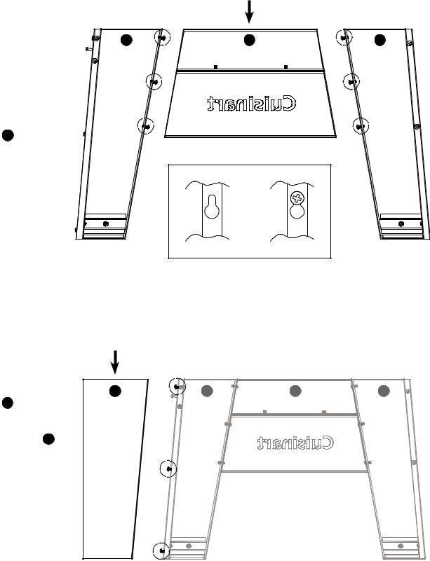
Step 1
•Loosen 6 screws 3-4 turns
•Do not remove screws
•Attach FRONT PANEL 2 using keyholes
•Tighten 6 screws
Step 2
•Loosen 3 screws
•Attach SIDE
PANEL 4
•Tighten 3 screws on SIDE PANEL 4
FRONT PANEL
1 |
2 |
3 |
NOTE: Before tightening keyhole screws, make sure panels are aligned.
SIDE PANEL
4 |
1 |
2 |
3 |
3
|
|
5 |
1 |
2 |
3 |
|
|
LEFT |
|
|
SIDE |
|
|
PANEL |
CART BRACE |
|
|
6 |
|
|
1 |
2 |
3 |
|
|
5 |
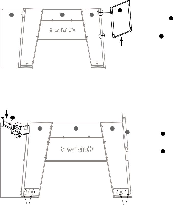
Step 3
•Loosen 2 screws
•Attach LEFT
SIDE PANEL 5
•Tighten 2 screws on LEFT SIDE
PANEL 5
Step 4
•Remove 6 screws.
•Attach CART BRACE. 6
•Tighten two screws on CART BRACE. 6
Remove 2 screws |
|
Remove 2 screws |
|
|
|
4
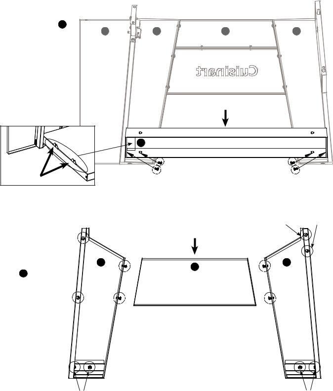
Step 5
• Attach CART BASE 7
4 |
1 |
2 |
3 |
• Make sure TANK
• BRACKETS are on this end. (See drawing below)
• Tighten 4 screws (Removed from Step 4)
CART BASE
7
Tighten 4 screws
TANK BRACKETS
Step 6 |
|
Remove 2 screws |
|
|
BACK PANEL |
||
|
|
|
|
• |
Loosen 6 screws |
|
|
• |
Attach BACK |
8 |
10 |
|
9 |
||
|
PANEL 9 |
|
|
• Tighten 4 screws
•Remove 6 screws
Remove 2 screws |
|
Remove 2 screws |
5
LEFT
SIDE
PANEL
7
CART BASE
Screws removed
from Step 6
5
8
9


 CART BRACE
10
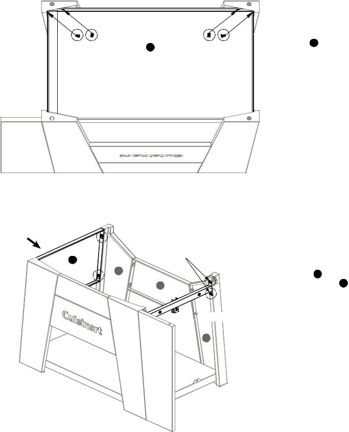
Step 7
•Attach CART BASE 7 to back legs
•Tighten 4 screws (Removed from Step 6)
Step 8
•Attach LEFT SIDE PANEL 5 and
CART BRACE 6
•Tighten 4 screws
6
 Loading...