


 Loading...
Professional Shop Manual
Z-Force S
NOTE: These materials are for use by trained technicians who are experienced in the service and repair of outdoor power equipment of the kind described in this publication, and are not intended for use by untrained or inexperienced individuals. These materials are intended to provide supplemental information to assist the trained technician. Untrained or inexperienced individuals should seek the assistance of an experienced and trained professional. Read, understand, and follow all instructions and use common sense when working on power equipment. This includes the contents of the product’s Operators Manual, supplied with the equipment. No liability can be accepted for any inaccuracies or omission in this publication, although care has been taken to make it as complete and accurate as possible at the time of publication. However, due to the variety of outdoor power equipment and continuing product changes that occur over time, updates will be made to these instructions from time to time. Therefore, it may be necessary to obtain the latest materials before servicing or repairing a product. The company reserves the right to make changes at any time to this publication without prior notice and without incurring an obligation to make such changes to previously published versions. Instructions, photographs and illustrations used in this publication are for reference use only and may not depict actual model and component parts.
© Copyright 2010 MTD Products Inc. All Rights Reserved
MTD Products Inc. - Product Training and Education Department
FORM NUMBER - 769-05513
06/2010
Table of Contents
Chapter 1: Introduction . . . . . . . . . . . . . . . . . . . . . . . . . . . . . . . . . . . . . . . . . . . . . 1
Professional Shop Manual intent . . . . . . . . . . . . . . . . . . . . . . . . . . . . . . . . . . . 1
Fasteners . . . . . . . . . . . . . . . . . . . . . . . . . . . . . . . . . . . . . . . . . . . . . . . . . . . . . 1 Assembly . . . . . . . . . . . . . . . . . . . . . . . . . . . . . . . . . . . . . . . . . . . . . . . . . . . . . 2
Description of the Z-Force-S . . . . . . . . . . . . . . . . . . . . . . . . . . . . . . . . . . . . . . . 2
Model and Serial Numbers . . . . . . . . . . . . . . . . . . . . . . . . . . . . . . . . . . . . . . . . 3
Chapter 2: Engine Related Parts . . . . . . . . . . . . . . . . . . . . . . . . . . . . . . . . . . . . . 5
Muffler . . . . . . . . . . . . . . . . . . . . . . . . . . . . . . . . . . . . . . . . . . . . . . . . . . . . . . . . 5
Fuel tank removal/replacement . . . . . . . . . . . . . . . . . . . . . . . . . . . . . . . . . . . . 6
Chapter 3: Brakes . . . . . . . . . . . . . . . . . . . . . . . . . . . . . . . . . . . . . . . . . . . . . . . . . 7
Brake system description . . . . . . . . . . . . . . . . . . . . . . . . . . . . . . . . . . . . . . . . . 7 Brake adjustment . . . . . . . . . . . . . . . . . . . . . . . . . . . . . . . . . . . . . . . . . . . . . . . 8 Brake puck/rotor replacement . . . . . . . . . . . . . . . . . . . . . . . . . . . . . . . . . . . . . . 9
Brake shaft assembly . . . . . . . . . . . . . . . . . . . . . . . . . . . . . . . . . . . . . . . . . . . 12
Parking brake lever . . . . . . . . . . . . . . . . . . . . . . . . . . . . . . . . . . . . . . . . . . . . . 14
Chapter 4: Body . . . . . . . . . . . . . . . . . . . . . . . . . . . . . . . . . . . . . . . . . . . . . . . . . 17
Floor pan . . . . . . . . . . . . . . . . . . . . . . . . . . . . . . . . . . . . . . . . . . . . . . . . . . . . . 17
Left control console . . . . . . . . . . . . . . . . . . . . . . . . . . . . . . . . . . . . . . . . . . . . . 19 Right control console . . . . . . . . . . . . . . . . . . . . . . . . . . . . . . . . . . . . . . . . . . . 23
Seat . . . . . . . . . . . . . . . . . . . . . . . . . . . . . . . . . . . . . . . . . . . . . . . . . . . . . . . . 26
Seat box assembly . . . . . . . . . . . . . . . . . . . . . . . . . . . . . . . . . . . . . . . . . . . . . 27
Chapter 5: Drive . . . . . . . . . . . . . . . . . . . . . . . . . . . . . . . . . . . . . . . . . . . . . . . . . 29
Drive belt . . . . . . . . . . . . . . . . . . . . . . . . . . . . . . . . . . . . . . . . . . . . . . . . . . . . . 29
Drive belt adjustment . . . . . . . . . . . . . . . . . . . . . . . . . . . . . . . . . . . . . . . . . . . 32 EZT transmission removal/replacement . . . . . . . . . . . . . . . . . . . . . . . . . . . . . 33
ZT 2800 transmission removal/replacement . . . . . . . . . . . . . . . . . . . . . . . . . . 35
Drive pedal biasing adjustment . . . . . . . . . . . . . . . . . . . . . . . . . . . . . . . . . . . . 38
Hydro neutral control adjustment . . . . . . . . . . . . . . . . . . . . . . . . . . . . . . . . . . 39
Chapter 6: Steering . . . . . . . . . . . . . . . . . . . . . . . . . . . . . . . . . . . . . . . . . . . . . . . 43
Introduction . . . . . . . . . . . . . . . . . . . . . . . . . . . . . . . . . . . . . . . . . . . . . . . . . . . 43
Wheel alignment and drive control link adjustments . . . . . . . . . . . . . . . . . . . . 43
Steering gear box removal . . . . . . . . . . . . . . . . . . . . . . . . . . . . . . . . . . . . . . . 47 Steering gearbox installation . . . . . . . . . . . . . . . . . . . . . . . . . . . . . . . . . . . . . 50
Rebuilding the steering gear box . . . . . . . . . . . . . . . . . . . . . . . . . . . . . . . . . . 54
Front wheels . . . . . . . . . . . . . . . . . . . . . . . . . . . . . . . . . . . . . . . . . . . . . . . . . . 67 Front yokes . . . . . . . . . . . . . . . . . . . . . . . . . . . . . . . . . . . . . . . . . . . . . . . . . . . 69
Removal of the steering gears . . . . . . . . . . . . . . . . . . . . . . . . . . . . . . . . . . . . 71
Tie rods . . . . . . . . . . . . . . . . . . . . . . . . . . . . . . . . . . . . . . . . . . . . . . . . . . . . . . 76 Steering shaft, bushings and dampener removal . . . . . . . . . . . . . . . . . . . . . . 79
I
Chapter 7: Electrical System .............................................................................. |
87 |
Introduction . . . . . . . . . . . . . . . . . . . . . . . . . . . . . . . . . . . . . . . . . . . . . . . . . . . |
87 |
RMC Module . . . . . . . . . . . . . . . . . . . . . . . . . . . . . . . . . . . . . . . . . . . . . . . . . . |
87 |
Key switch . . . . . . . . . . . . . . . . . . . . . . . . . . . . . . . . . . . . . . . . . . . . . . . . . . . . |
88 |
RMC Module . . . . . . . . . . . . . . . . . . . . . . . . . . . . . . . . . . . . . . . . . . . . . . . . . . |
90 |
To identify a faulty RMC module . . . . . . . . . . . . . . . . . . . . . . . . . . . . . . . . . . . |
91 |
PTO Switch . . . . . . . . . . . . . . . . . . . . . . . . . . . . . . . . . . . . . . . . . . . . . . . . . . . |
93 |
Parking Brake Switch . . . . . . . . . . . . . . . . . . . . . . . . . . . . . . . . . . . . . . . . . . . |
93 |
Reverse Safety Switch . . . . . . . . . . . . . . . . . . . . . . . . . . . . . . . . . . . . . . . . . . |
94 |
Seat Safety Switch . . . . . . . . . . . . . . . . . . . . . . . . . . . . . . . . . . . . . . . . . . . . . |
94 |
Starter solenoid . . . . . . . . . . . . . . . . . . . . . . . . . . . . . . . . . . . . . . . . . . . . . . . . |
95 |
PTO Relay . . . . . . . . . . . . . . . . . . . . . . . . . . . . . . . . . . . . . . . . . . . . . . . . . . . |
95 |
Lighting circuit . . . . . . . . . . . . . . . . . . . . . . . . . . . . . . . . . . . . . . . . . . . . . . . . . |
96 |
Start Circuit . . . . . . . . . . . . . . . . . . . . . . . . . . . . . . . . . . . . . . . . . . . . . . . . . . . |
96 |
Run Circuit . . . . . . . . . . . . . . . . . . . . . . . . . . . . . . . . . . . . . . . . . . . . . . . . . . . . |
99 |
Run Circuit / Reverse Caution mode . . . . . . . . . . . . . . . . . . . . . . . . . . . . . . . |
100 |
Engine shut-down circuits . . . . . . . . . . . . . . . . . . . . . . . . . . . . . . . . . . . . . . . |
101 |
Charging circuit . . . . . . . . . . . . . . . . . . . . . . . . . . . . . . . . . . . . . . . . . . . . . . . |
102 |
PTO Circuit . . . . . . . . . . . . . . . . . . . . . . . . . . . . . . . . . . . . . . . . . . . . . . . . . . |
107 |
Reverse Mower Control (RMC) circuit operation . . . . . . . . . . . . . . . . . . . . . |
109 |
Electrical diagnosis . . . . . . . . . . . . . . . . . . . . . . . . . . . . . . . . . . . . . . . . . . . . |
111 |
Electronics . . . . . . . . . . . . . . . . . . . . . . . . . . . . . . . . . . . . . . . . . . . . . . . . . . |
111 |
Electrical environment: AC Vs. DC . . . . . . . . . . . . . . . . . . . . . . . . . . . . . . . . |
112 |
Ohm’s Law . . . . . . . . . . . . . . . . . . . . . . . . . . . . . . . . . . . . . . . . . . . . . . . . . . |
113 |
Kirchhoff’s current law . . . . . . . . . . . . . . . . . . . . . . . . . . . . . . . . . . . . . . . . . |
113 |
Kirchhoff’s voltage law . . . . . . . . . . . . . . . . . . . . . . . . . . . . . . . . . . . . . . . . . |
114 |
How the system is wired together . . . . . . . . . . . . . . . . . . . . . . . . . . . . . . . . . |
114 |
Types of circuits . . . . . . . . . . . . . . . . . . . . . . . . . . . . . . . . . . . . . . . . . . . . . . |
115 |
Series . . . . . . . . . . . . . . . . . . . . . . . . . . . . . . . . . . . . . . . . . . . . . . . . . . . . . . |
115 |
Parallel . . . . . . . . . . . . . . . . . . . . . . . . . . . . . . . . . . . . . . . . . . . . . . . . . . . . . |
115 |
Series/parallel . . . . . . . . . . . . . . . . . . . . . . . . . . . . . . . . . . . . . . . . . . . . . . . . |
116 |
Shorts . . . . . . . . . . . . . . . . . . . . . . . . . . . . . . . . . . . . . . . . . . . . . . . . . . . . . . |
116 |
Opens . . . . . . . . . . . . . . . . . . . . . . . . . . . . . . . . . . . . . . . . . . . . . . . . . . . . . . |
116 |
Increased resistance . . . . . . . . . . . . . . . . . . . . . . . . . . . . . . . . . . . . . . . . . . . |
116 |
The Tools . . . . . . . . . . . . . . . . . . . . . . . . . . . . . . . . . . . . . . . . . . . . . . . . . . . |
117 |
Digital Multi-meter . . . . . . . . . . . . . . . . . . . . . . . . . . . . . . . . . . . . . . . . . . . . . |
118 |
Wiring diagram or schematic . . . . . . . . . . . . . . . . . . . . . . . . . . . . . . . . . . . . |
119 |
Fused jumper wires . . . . . . . . . . . . . . . . . . . . . . . . . . . . . . . . . . . . . . . . . . . |
119 |
Test lights . . . . . . . . . . . . . . . . . . . . . . . . . . . . . . . . . . . . . . . . . . . . . . . . . . . |
119 |
Self-powered continuity lights . . . . . . . . . . . . . . . . . . . . . . . . . . . . . . . . . . . . |
119 |
Ammeters and specialized charging system testers . . . . . . . . . . . . . . . . . . . |
120 |
Batteries . . . . . . . . . . . . . . . . . . . . . . . . . . . . . . . . . . . . . . . . . . . . . . . . . . . . |
121 |
Charging the battery . . . . . . . . . . . . . . . . . . . . . . . . . . . . . . . . . . . . . . . . . . . |
121 |
Checking battery condition . . . . . . . . . . . . . . . . . . . . . . . . . . . . . . . . . . . . . . |
122 |
Battery Testers . . . . . . . . . . . . . . . . . . . . . . . . . . . . . . . . . . . . . . . . . . . . . . . |
123 |
Adjustable load testers . . . . . . . . . . . . . . . . . . . . . . . . . . . . . . . . . . . . . . . . . |
123 |
II
Fixed load testers . . . . . . . . . . . . . . . . . . . . . . . . . . . . . . . . . . . . . . . . . . . . . |
124 |
Conductance testers . . . . . . . . . . . . . . . . . . . . . . . . . . . . . . . . . . . . . . . . . . . |
124 |
Battery discharge test . . . . . . . . . . . . . . . . . . . . . . . . . . . . . . . . . . . . . . . . . . |
125 |
Storage of batteries . . . . . . . . . . . . . . . . . . . . . . . . . . . . . . . . . . . . . . . . . . . |
125 |
Electrical Troubleshooting . . . . . . . . . . . . . . . . . . . . . . . . . . . . . . . . . . . . . . |
126 |
Voltage Drop Test . . . . . . . . . . . . . . . . . . . . . . . . . . . . . . . . . . . . . . . . . . . . . |
128 |
Testing switches . . . . . . . . . . . . . . . . . . . . . . . . . . . . . . . . . . . . . . . . . . . . . . |
131 |
Diodes . . . . . . . . . . . . . . . . . . . . . . . . . . . . . . . . . . . . . . . . . . . . . . . . . . . . . . |
132 |
Relay . . . . . . . . . . . . . . . . . . . . . . . . . . . . . . . . . . . . . . . . . . . . . . . . . . . . . . . |
134 |
Schematic . . . . . . . . . . . . . . . . . . . . . . . . . . . . . . . . . . . . . . . . . . . . . . . . . . . |
135 |
Chapter 8: Decks And Lift Shaft ....................................................................... |
137 |
Cutting decks . . . . . . . . . . . . . . . . . . . . . . . . . . . . . . . . . . . . . . . . . . . . . . . . |
137 |
Cleaning the deck . . . . . . . . . . . . . . . . . . . . . . . . . . . . . . . . . . . . . . . . . . . . . |
138 |
To clean the deck while it is removed . . . . . . . . . . . . . . . . . . . . . . . . . . . . . . |
138 |
Blades . . . . . . . . . . . . . . . . . . . . . . . . . . . . . . . . . . . . . . . . . . . . . . . . . . . . . . |
139 |
PTO belt . . . . . . . . . . . . . . . . . . . . . . . . . . . . . . . . . . . . . . . . . . . . . . . . . . . . |
141 |
Deck Belt . . . . . . . . . . . . . . . . . . . . . . . . . . . . . . . . . . . . . . . . . . . . . . . . . . . |
142 |
Belt tension . . . . . . . . . . . . . . . . . . . . . . . . . . . . . . . . . . . . . . . . . . . . . . . . . . |
143 |
Spindle pulleys and spindle shafts . . . . . . . . . . . . . . . . . . . . . . . . . . . . . . . . |
144 |
Spindle removal/installation . . . . . . . . . . . . . . . . . . . . . . . . . . . . . . . . . . . . . |
145 |
Spindle overhaul . . . . . . . . . . . . . . . . . . . . . . . . . . . . . . . . . . . . . . . . . . . . . . |
146 |
Leveling the deck . . . . . . . . . . . . . . . . . . . . . . . . . . . . . . . . . . . . . . . . . . . . . |
148 |
Side to Side Leveling . . . . . . . . . . . . . . . . . . . . . . . . . . . . . . . . . . . . . . . . . . |
148 |
Front To Rear (pitch) Leveling . . . . . . . . . . . . . . . . . . . . . . . . . . . . . . . . . . . |
149 |
Deck Gauge Wheel Adjustment . . . . . . . . . . . . . . . . . . . . . . . . . . . . . . . . . . |
150 |
Front and rear deck lift shaft assembly . . . . . . . . . . . . . . . . . . . . . . . . . . . . . |
151 |
Deck lift pedal lever . . . . . . . . . . . . . . . . . . . . . . . . . . . . . . . . . . . . . . . . . . . |
153 |
Chapter 9: Maintenance Intervals ..................................................................... |
155 |
Lubrication . . . . . . . . . . . . . . . . . . . . . . . . . . . . . . . . . . . . . . . . . . . . . . . . . . |
155 |
Engine maintenance . . . . . . . . . . . . . . . . . . . . . . . . . . . . . . . . . . . . . . . . . . . |
155 |
The spark plugs . . . . . . . . . . . . . . . . . . . . . . . . . . . . . . . . . . . . . . . . . . . . . . . |
156 |
Air filter. . . . . . . . . . . . . . . . . . . . . . . . . . . . . . . . . . . . . . . . . . . . . . . . . . . . . . |
157 |
Oil change . . . . . . . . . . . . . . . . . . . . . . . . . . . . . . . . . . . . . . . . . . . . . . . . . . . |
158 |
Oil filter. . . . . . . . . . . . . . . . . . . . . . . . . . . . . . . . . . . . . . . . . . . . . . . . . . . . . . |
159 |
Fuel system . . . . . . . . . . . . . . . . . . . . . . . . . . . . . . . . . . . . . . . . . . . . . . . . . |
160 |
Servicing the fuel system . . . . . . . . . . . . . . . . . . . . . . . . . . . . . . . . . . . . . . . |
160 |
Fuel filter . . . . . . . . . . . . . . . . . . . . . . . . . . . . . . . . . . . . . . . . . . . . . . . . . . . . |
160 |
Clean the engine . . . . . . . . . . . . . . . . . . . . . . . . . . . . . . . . . . . . . . . . . . . . . . |
161 |
Transmissions . . . . . . . . . . . . . . . . . . . . . . . . . . . . . . . . . . . . . . . . . . . . . . . . |
161 |
III
IV

Introduction
CHAPTER 1: INTRODUCTION
Professional Shop Manual intent
This Manual is intended to provide service dealers with an introduction to the mechanical aspects of the Z-Force- S riding mower.
•Detailed service information about the engine will be provided by the engine manufacturer, in most cases.
Disclaimer: The information contained in this manual is correct at the time of writing. Both the product and the information about the product are subject to change without notice.
About the text format:
NOTE: is used to point out information that is relevant to the procedure, but does not fit as a step in the procedure.
•Bullet points: indicate sub-steps or points.
|
|
|
|
|
|
|
|
|
|
Caution is used to point out potential danger to the technician, operator, bystanders, or sur- |
|
|
|
! CAUTION |
|
||
|
|
|
rounding property. |
|
|
|
|
|
|
|
|
|
|
|
|
|
|
|
|
|
|
|
|
|
|
|
|
|
|
|
|
|
|
Warning indicates a potentially hazardous situation that, if not avoided, could result in death of |
|
|
|
! WARNING |
|
||
|
|
|
serious injury. |
|
|
|
|
|
|
|
|
|
|
|
|
|
|
|
|
|
|
|
|
|
|
|
|
|
|
|
|
|
|
Danger indicates an imminently hazardous situation that, if not avoided, will result in death or |
|
|
|
! DANGER |
|
||
|
|
|
serious injury. This signal word is to be limited to the most extreme situations |
|
|
|
|
|
|
|
|
|
|
|
|
|
|
Disclaimer: This manual is intended for use by trained, professional technicians.
•Common sense in operation and safety is assumed.
•In no event shall MTD or Cub Cadet be liable for poor text interpretation or poor execution of the procedures described in the text.
•If the person using this manual is uncomfortable with any procedures they encounter, they should seek the help of a qualified technician or Cub Cadet Technical Support.
Fasteners
•Most of the fasteners used on these mowers are sized in fractional inches. The engine and transmissions are metric. For this reason, wrench sizes are frequently identified in the text, and measurements are given in U.S. and metric scales.
•If a fastener has a locking feature that has worn, replace the fastener or apply a small amount of releasable thread locking compound such as Loctite® 242 (blue).
•Some fasteners like cotter pins are single-use items that are not to be reused. Other fasteners such as lock washers, retaining rings, and internal cotter pins (hairpin clips) may be reused if they do not show signs of wear or damage. This manual leaves that decision to the judgement of the technician.
1

Z-Force-S
Assembly
Torque specifications may be noted in the part of the text that covers assembly, they may also be summarized in tables along with special instructions regarding locking or lubrication. Whichever method is more appropriate will be used. In many cases, both will be used so that the manual is handy as a quick-reference guide as well as a step-by- step procedure guide that does not require the user to hunt for information.
The level of assembly instructions provided will be determined by the complexity and of reassembly, and by the potential for unsafe conditions to arise from mistakes made in assembly.
Some instructions may refer to other parts of the manual for subsidiary procedures. This avoids repeating the same procedure two or three times in the manual.
Description of the Z-Force-S
The Z-Force-S combines a traditional Z-force lap bar zero turn rider (ZTR) with Cub Cadet’s patented Syncro SteerTM technology.
The magic of the system: variable ratio steering gears that turn the front wheels much further than conventional systems. The steering control is linked to the traction drive system control.
The traction drive system synchronizes the steering angle of the front tires with the speed and direction of the rear tires.
A true zero-turn is achieved when the operator turns |
|
the steering wheel far enough that the inside rear wheel |
|
spins in reverse just like a traditional lap-bar controlled |
Figure 1.1 |
ZTR. |
2
Introduction
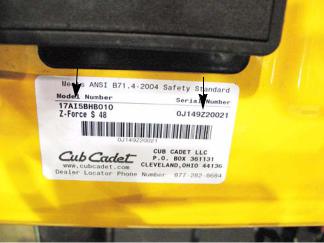
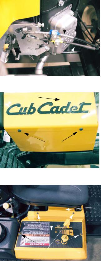
Model and Serial Numbers
Model number Serial number
Figure 1.2
The model and serial number tag can be found under the seat. See Figure 1.2.
The serial number is located to the right of the model number as shown above. See Figure 1.2.
The model number is 17AI5BHB010. The break down of what the number mean is as follows:
1 ............................................................................................... |
Residential machine |
....7 ........................................................................................... |
Residential zero turn mower |
.......A........................................................................................ |
Sales level |
...........I. .................................................................................... |
Engine code |
.............5. ................................................................................. |
Frame |
.................B.............................................................................. |
Transmission (B = EZT, G = ZT2800) |
....................H .......................................................................... |
Style series |
.........................B...................................................................... |
Deck (B = 48”, D = 60”) |
.............................010 .............................................................. |
Customer number |
The serial number is 0J149Z20021. The serial number reads as follows: |
|
0 ............................................................................................... |
Engineering level |
..J ............................................................................................. |
Month of production (J = October) |
.....14 ........................................................................................ |
Day of the month |
.........9 ...................................................................................... |
Last digit of the year |
...........Z.................................................................................... |
Plant it was built in (Streetsboro, OH) |
..............2 ................................................................................. |
Assembly line number |
.................0005 ........................................................................ |
Number of unit built |
3
Z-Force-S
4
Engine Related Parts
CHAPTER 2: ENGINE RELATED PARTS
This chapter will cover the engine accessories that are manufactured by Cub Cadet.
IMPORTANT: The engine is manufactured by Kawasaki. Refer to the Kawasaki manual for engine specific service information.
Muffler
Remove the muffler by following these steps:
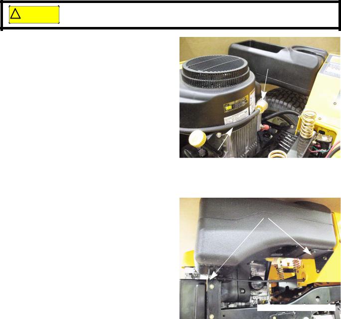
Bumper
1. Remove the six nuts and bolts (three on each side)
that hold the rear bumper in place using a pair of 1/2” wrenches. See Figure 2.1.
2. Slide the bumper out from between the frame, the fuel tank bracket on the right and utility bin bracket on the left.
Fuel tank support bracket
Figure 2.1
|
3. |
Remove the two nuts that hold each exhaust pipe to |
|
|
the cylinder head using a 13 mm wrench. |
|
|
See Figure 2.2. |
|
4. |
Remove the muffler and exhaust pipes. |
13 mm wrench size |
NOTE: The exhaust pipes are welded to the muffler. The |
|
|
pipes and the muffler are serviced as one assem- |
|
|
|
|
|
Exhaust pipe |
bly. |
|
5. |
Clean and remove all gasket material from the cylin- |
|
|
der head (and the exhaust pipe if they are being |
|
|
reused). |
|
6. |
Using new gaskets, install the muffler by following the |
|
|
previous steps in reverse order. |
Figure 2.2 |
NOTE: Tighten the exhaust nuts to a torque of 120 ft lbs |
|
|
|
(14Nm). |
|
NOTE: When installing the bumper, insert all six bolts |
|
|
|
before tightening them. Otherwise the bumper will |
|
|
bind and the holes will not line up. |
|
7. |
Test drive the mower in a safe area before returning it |
|
|
to service. |
5
Z-Force-S
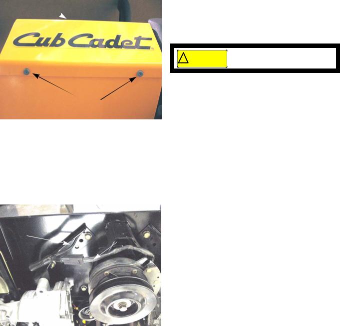
Fuel tank removal/replacement
Remove/replace the fuel tank by following these steps:
Gasoline and its vapors are extremely flammable. Use common sense when working around
!CAUTION the fuel system
1.Clamp off the fuel line between the fuel tank and the fuel filter.
Fuel filter 2. Disconnect the fuel line from the fuel tank at the fuel 
filter.
3. Drain the fuel into an approved container.
Fuel line from the fuel tank
Figure 2.3
4. |
Remove the fuel tank by removing the four screws |
Support brackets |
|
that hold it to the support brackets using a 9/16” |
|
|
|
wrench. See Figure 2.4.
5.Install the fuel tank by following the previous steps in reverse order.
6.Test drive the mower in a safe area before returning it to service.
Figure 2.4
6

Brakes
CHAPTER 3: BRAKES
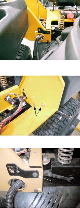
Brake system description
The Z-Force-S uses twin HydroGear transmissions to drive the rear wheels. The hydraulic action of the transmissions will provide the braking for the mower while it is in motion. There is a friction brake on the transmission, but it is used as a parking brake.
NOTE: Mowers equipped with a 48” deck have HydroGear EZT transmissions with the brakes on the inboard side of the transmissions (shown below). Mowers with the 60” deck are equipped with HydroGear ZT2800 transmissions. The brakes for the ZT2800 transmissions are mounted to the frame of the mower on the outboard side of the transmissions. The brakes for both the EZT and the ZT2800 transmissions function and are serviced the same way.
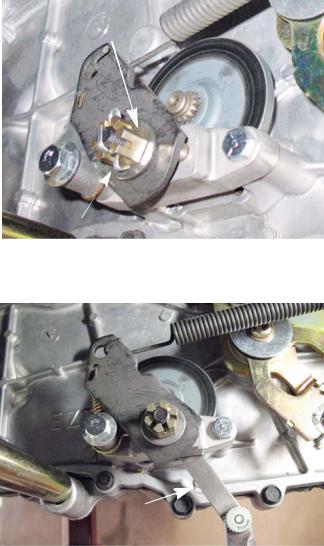
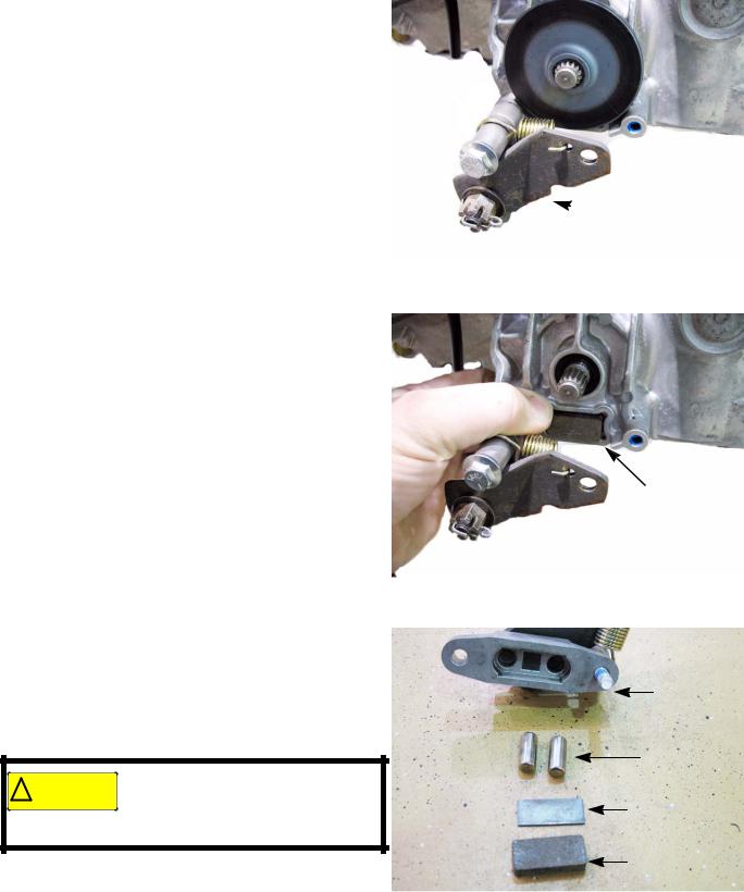
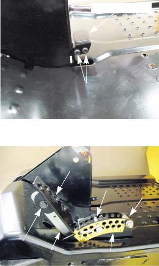
Cam arm
 Brake pins
Figure 3.1
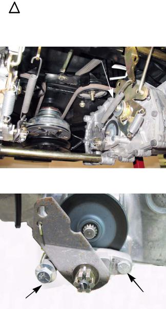
Center bell crank
Brake
shaft
Brake bell cranks
•There is a brake for each transmission.
•They are activated by moving the parking brake lever to the “ON” position.
•The parking brake lever operates the brake shaft.
•The brake shaft has three bell cranks. The two outer bell cranks are for applying the brakes. They are connected to the brake caliper cam arms by extension springs.
•When the cam arms are pulled forward, they push on the brake pins with a cam action applying pressure to the brake pads. See Figure 3.1.
•The center bell crank on the brake cross shaft assembly has a link that is connected to the drive belt idler pulley bracket. When the parking brakes are applied, the idler pulleys are pulled away from the drive belt. This de-tensions the belt, disengaging drive to the transmissions. See Figure 3.2. The adjustment procedure for the brake link is covered in the drive belt adjustment section of Chapter 5: Drive.
Figure 3.2
7
Z-Force-S
Brake adjustment
NOTE: When performing a brake adjustment, inspect the brake components for signs of wear or damage.
1.Block the front wheels.
2.Lift and safely support the rear of the mower. NOTE: Make sure the parking brake is released.
3.Remove the cotter pin locking the castle nut on the brake caliper. See Figure 3.3.
4.Back the castle nut off a few turns using a 9/16” wrench.
NOTE: Even if the brakes are set to the correct clearance, inserting a feeler gauge between the rotor and the brake puck can be very difficult. Loosen the castle nut first, then insert the feeler gauge and tighten the nut to set the proper clearances
5.Insert a 0.030” (0.8 mm) feeler gauge between the brake rotor and the outboard brake puck.
See Figure 3.4.
NOTE: The tolerance for the brake clearance is 0.020” - 0.040” (0.5 - 1.0mm). The 0.030 feeler gauge will set the clearance at the midpoint.
6.Tighten the nut until there is slight drag on the feeler gauge.
NOTE: For even braking, both sides should be set to the same clearance.
7.Install a new cotter pin.
8.Repeat same procedure on the other side.
Castellated nut
Cotter pin
pin
Figure 3.3
0.030” feeler gauge
Figure 3.4
9.Take the mower off of the jack stands.
10.Open the by-pass valves and check the parking brake before returning the mower to service.
•With the brakes released, the mower should have only hydraulic drag when it is pushed.
•With the brakes engaged, the wheels should slide before they rotate when the mower is pushed.
11.Test drive the mower in a safe area before returning it to service.
8
Brakes
Brake puck/rotor replacement
On HydroGear transmissions, the brake pucks are wearing parts that will need to be serviced from time to time. If a mower is operated with the parking brake dragging, the pucks will wear out rapidly and the brake rotor will develop hot spots. If the mower is operated long enough, the rotor may have grinding marks on it with excessively worn pucks.
|
|
|
|
|
|
|
|
If the rotor shows hot spots or any other signs of damage, including warpage, it must be |
|
|
|
! CAUTION |
||
|
|
replaced. Failure to do so can result in the failure of the brakes |
|
|
|
|
|
|
|
|
|
|
|
|
The brake pucks and the rotors are serviced at the same time. To service the brake pucks:
Brake spring
1. Lift and safely support the rear of the mower. 2. Make sure the parking brake is released.
3. Disconnect the brake springs. See Figure 3.5.
Figure 3.5
4. Loosen the rear mounting bolt. See Figure 3.6.
Loosen this bolt |
Remove this |
bolt |
|
|
Figure 3.6 |
9
Z-Force-S
5.Remove the front mounting bolt, allowing the caliper to swing down. See Figure 3.7.
6.The outboard brake puck should fall out when the brake caliper swings down. If it did not, it can be removed now.
7.Slide the brake rotor off to reach the inboard brake puck. See Figure 3.8.
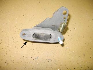
8.Remove the caliper for inspection when servicing the brake pucks. To do this, remove the rear bolt loosened in step 4.
9.With the caliper on a work bench, remove the brake puck, backing plate and the two brake pins.
See Figure 3.9.
10.Check for free movement of the brake pins. A dry lubricant can be used on the brake pins sparingly.
Never put grease or anti-seize on
! CAUTION brake pins. It can migrate to the brake pucks, preventing the braking action
of the pucks.
11.Slide the brake pins into the caliper.
12.Place the backing plate in the caliper.

 Caliper
Figure 3.7
 Inboard brake puck
Figure 3.8
Brake caliper
Brake pins
Backing plate
Brake puck
Figure 3.9
10
Brakes
Brake caliper re-assembled
Figure 3.10
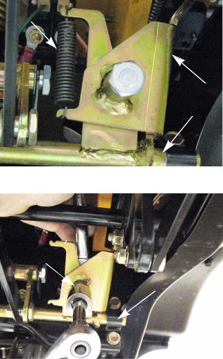
13. Place a new puck into the caliper. See Figure 3.10.
NOTE: A piece of scotch tape may be used to hold the new brake pucks in place for assembly. The tape will grind away when the brakes are applied.
14.Place a new brake puck into the recess in the transmission. Use a piece of scotch tape to hold it in place.
15.Slide the brake rotor in place, shoulder out.
16.Mount the brake caliper to the transmission. Apply a small amount of releasable thread locking compound such as Loctite® 242 (blue) to the mounting bolts and tighten to a torque of 80 - 120 in-lbs (9 - 13.5Nm).
17.Reconnect the brake spring.
18.Adjust the brakes as described in the previous section of this chapter.
19.Repeat steps 4-19 on the other side.
20.When both sides are completed, take the mower off of the jack stands.
21.Open the by-pass valves and check the parking brake before returning the mower to service.
•With the brakes released, the mower should have only hydraulic drag when it is pushed.
•With the brakes engaged, the wheels should slide before they rotate when the mower is pushed.
22.Test drive the mower in a safe area before returning it to service.
11

Z-Force-S
Brake shaft assembly
To remove/replace the brake shaft:
1.Remove the cutting deck by following the procedures described in Chapter 8: Cutting Decks and Lift shaft.
2.Lift and safely support the rear of the mower.
3.If the parking brake is set, release it.
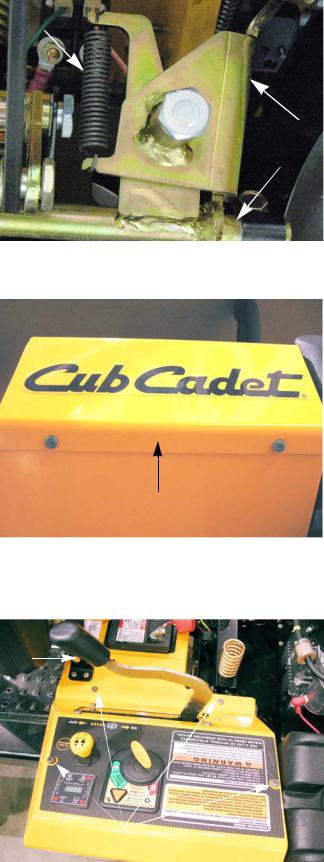
4.Disconnect the brake springs. See Figure 3.11.
5.Disconnect the link that runs from the idler bracket to the brake shaft by removing the cotter pin.
See Figure 3.12.
6.Disconnect the adjustable drive links from the pivot arms by removing the bow tie clips at the ferrule end of the link. See Figure 3.13.
Brake springs
Figure 3.11
Cotter pin
 Link
Link
Figure 3.12
bow tie clip
Adjustable drive links
Figure 3.13
12
Spring
Brake lever
Brake shaft
Brakes
7.Remove the extension spring that runs from the brake lever to the brake shaft. See Figure 3.14.
Figure 3.14
9/16” wrench 3/4” wrench
Clamp
Figure 3.15
8.Remove the nut and shoulder bolt that attaches the brake lever to the brake shaft using a 9/16” wrench and a 3/4” wrench. See Figure 3.15.
9.Remove the clamps (one on each side) that hold the brake shaft to the frame of the mower. Use a 1/2” wrench.
10.Install the brake shaft by following the previous steps in reverse order.
11.Test drive the mower in a safe area before returning it to service.
13
Z-Force-S
Parking brake lever
Spring
To remove/replace the parking brake lever:
1.Remove the cutting deck by following the procedures described in Chapter 8: Cutting Decks and Lift shaft.
2.Move the parking brake lever to the “OFF” position.
3.Remove the extension spring that runs from the brake lever to the brake shaft. See Figure 3.16.
NOTE: When the parking brake lever is in the “ON” position, this spring pulls on the lever applying pressure to the parking brake switch.
Figure 3.16
4.Remove the two screws from the underside of the left control panel using a T-30 torx driver.
See Figure 3.17.
Left control panel
Figure 3.17
5.Remove the grip from the parking brake lever. See Figure 3.18.
6.Remove the two screws that hold the left control panel to the seat box assembly using a T-30 torx driver. See Figure 3.18.
7.Remove the two screws that hold the control panel to the control pods using a T-30 torx driver.
Grip
Screws
Figure 3.18
Brake lever
Brake shaft
14
Brakes
8.Carefully raise the control panel enough to gain access to the inside of the control pod.
9.Disconnect the spring that runs from the parking brake lever to the frame of the mower.
See Figure 3.19.
Parking brake spring
Figure 3.19
9/16” wrench 3/4” wrench
Clamp
10.Remove the nut and shoulder bolt that attach the brake lever to the brake shaft using a 9/16” wrench and a 3/4” wrench. See Figure 3.20.
11.Remove the parking brake lever.
Figure 3.20
Parking brake lever
Plastic bushings
Shoulder bolt |
Nylock nut |
|
|
|
Figure 3.21 |
12.Remove and inspect the plastic bushings for signs of wear or damage.
NOTE: If there are signs of damage or wear, replace the bushings.
13.Install the parking brake lever by following the previous steps in reverse order.
14.Test drive the mower in a safe area before returning it to service.
15
Z-Force-S
16
Body
CHAPTER 4: BODY
Floor pan
To remove/replace the floor pan:
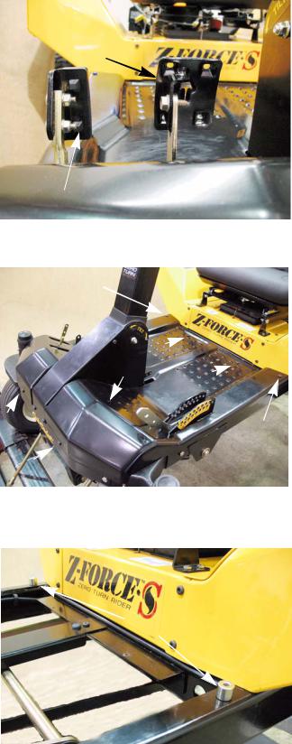
Tilt steering pedal
1. Remove the deck by following the procedures described in Chapter 8: Decks and Lift Shafts.
2. Remove the two screws that hold the tilt steering pedal using a T-30 torx driver. See Figure 4.1.
3. Remove the tilt steering pedal.
Screws
Figure 4.1
Deck lift pedal
Clevis pin
Spacer
Shoulder bolt |
|
Lift pedal arm |
Deck lift indexing bracket |
|
Figure 4.2 |
4.Remove the rear nut, bolt and spacer from the deck lift indexing bracket using a pair of 9/16” wrenches. See Figure 4.2.
5.Remove the clevis pin from the deck lift indexing bracket. See Figure 4.2.
6.Lower the deck lift pedal.
7.Remove the pedal by removing the shoulder bolt and nut using a pair of 9/16” wrenches.
NOTE: On mowers equipped with a 60” deck, there are two lift assist springs. With the deck removed, these springs will hold the lift pedal arm in the forward position with great force.
17
Z-Force-S
8.Remove the reverse pedal using a 7/16” wrench. See Figure 4.3.
9.Remove the drive pedal using a 1/2” wrench. See Figure 4.3.
10.Remove the eight screws that hold the floor pan to the frame using a T-30 torx driver. See Figure 4.4.
NOTE: The two outboard screws next to the seat box are longer than the rest. They also pass through a pair of spacers.
11.Lift the floor pan off of the mower.
NOTE: Under the floor pan there are two spacers. See Figure 4.5.
12.Install the floor pan by following the previous steps in reverse order.
Drive pedal
Reverse pedal
Figure 4.3
Long screw
Long screw
Figure 4.4
 Spacers
Figure 4.5
18
Left control console
left control panel
Screws 
Figure 4.6
Ground cable
PTO clutch harness
Figure 4.7
Body
To remove/replace the left side control console:
1.Disconnect the negative battery cable.
2.Remove the deck by following the procedures described in Chapter 8: Decks and Lift Shafts.
Release the parking brake before
!CAUTION the control panel.
3.Remove the two screws from the underside of the left control panel using a T-30 torx driver. See Figure 4.6.
NOTE: Technicians with good dexterity can remove the RMC module, PTO switch and hour meter with out removing the left control panel.
•Release the parking brake
•Remove the four screws that hold the park brake locking plate to the control panel.
•Gentle lower the locking bracket to prevent damage to the parking brake switch.
•Reach into the opening to access the switches.
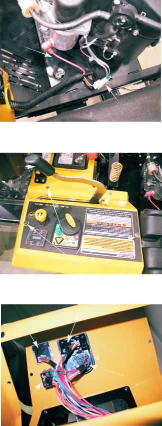
4.Disconnect the PTO clutch harness. See Figure 4.7.
5.Disconnect the ground cable from the frame. See Figure 4.7.
19
Z-Force-S
6.Disconnect the engine harness from the main harness. See Figure 4.8.
7. |
Disconnect the starter cable. See Figure 4.8. |
Starter |
|
|
cable |
Engine harness connector
Figure 4.8
8.Remove the grip from the parking brake lever. See Figure 4.9.
9.Remove the two screws that hold the left control panel to the seat box assembly using a T-30 torx driver. See Figure 4.9.
10.Remove the two screws that hold the control panel to the control consoles using a T-30 torx driver.
11.Carefully lift up on the control panel to gain access to the wiring under it.
12.Disconnect the wiring harness from the switches and modules. See Figure 4.10.
13.Lift the control panel off of the mower.
NOTE: If the control panel is being replaced, remove the switches and modules from it and install them on the new control panel.
Grip
Screws
Figure 4.9
RMC module
Hour meter
Key switch
PTO switch
Figure 4.10
20
Body
14. Disconnect the deck lift assist spring. See Figure 4.11.
NOTE: The lift assist spring exerts a lot of force.
Lift assist spring
Figure 4.11
15. Remove the nuts and bolts that hold the utility bin bracket to the control console using a pair of 1/2” wrenches. See Figure 4.12.
Nuts
1/2” wrench
Figure 4.12
16. Remove the two screws that hold the rear of the control console to the seat box assembly using a T-30 torx driver and a 7/16” wrench. See Figure 4.13.
NOTE: The upper screw goes through a reinforcement plate for the lift assist spring.
Screws
Figure 4.13
21
Z-Force-S
17.Remove the screws that hold the front of the control console to the front of the seat box assembly using a T-30 torx driver and a 7/16” wrench. See Figure 4.21.
18.Gently pull the harness through the hole in the console while lifting it off of the mower.
19.Install the control console by following the previous steps in reverse order.
20.Test drive the mower in a safe area before returning it to service.
Screws
Figure 4.14
22
Right control console
Choke cable
Throttle cable
cable
Figure 4.15
right control panel
 Screws
Body
To remove/replace the right side control console:
1.Disconnect the choke and throttle cables from the engine. See Figure 4.15.
NOTE: Paint marking and color coding the cables will make reassembly easier.
NOTE: On mowers equipped with the 60” decks, remove the deck by following the procedures described in Chapter 8: Decks and Lift Shafts.
2.Remove the two screws from the underside of the right control panel using a T-30 torx driver.
See Figure 4.16.
Figure 4.16
Right control panel
Seat
box assembly
Screws
Figure 4.17
3.Remove the two screws that hold the right control panel to the seat box assembly using a T-30 torx driver. See Figure 4.17.
4.Remove the two screws that hold the control panel to the control consoles using a T-30 torx driver.
5.Lift the control panel off of the control console.
NOTE: If the control panel is being replaced, remove the throttle and choke cables from it and install them on the new control panel.
23

Z-Force-S
NOTE: On mowers equipped with a 60” deck, disconnect the deck lift assist spring.
6.Remove the nuts and bolts that hold the fuel tank bracket to the control console using a pair of 1/2” wrenches. See Figure 4.19.
7.Remove the two screws that hold the rear of the control console to the seat box assembly using a T- 30 torx driver and a 7/16” wrench. See Figure 4.20.
NOTE: On mowers equipped with a 60” deck, the upper screw will go through a reinforcement plate for the lift assist spring.
Lift assist spring
Figure 4.18
1/2” wrenches
Figure 4.19
7/16” wrench
T-30 driver
Figure 4.20
24
Loading...