


 Loading...
Service Manual
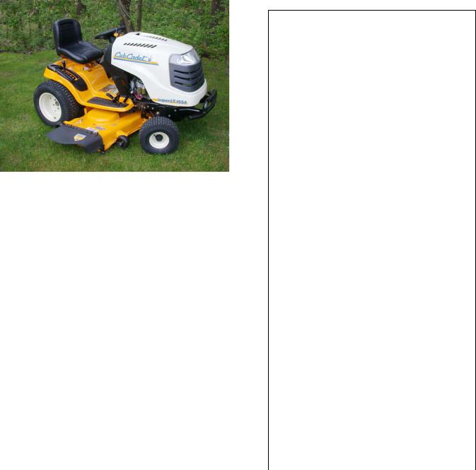
1000/1500 Series Riding Tractors
NOTE: These materials are for use by trained technicians who are experienced in the service and repair of outdoor power equipment of the kind described in this publication, and are not intended for use by untrained or inexperienced individuals. These materials are intended to provide supplemental information to assist the trained technician. Untrained or inexperienced individuals should seek the assistance of an experienced and trained professional. Read, understand, and follow all instructions and use common sense when working on power equipment. This includes the contents of the product’s Operators Manual, supplied with the equipment. No liability can be accepted for any inaccuracies or omission in this publication, although care has been taken to make it as complete and accurate as possible at the time of publication. However, due to the variety of outdoor power equipment and continuing product changes that occur over time, updates will be made to these instructions from time to time. Therefore, it may be necessary to obtain the latest materials before servicing or repairing a product. The company reserves the right to make changes at any time to this publication without prior notice and without incurring an obligation to make such changes to previously published versions. Instructions, photographs and illustrations used in this publication are for reference use only and may not depict actual model and component parts.
© Copyright 2006 MTD Products Inc. All Rights Reserved
MTD Products Inc. - Product Training and Education Department
FORM NUMBER - 769-02100 1/2006
|
Table of Contents |
|
1. |
INTRODUCTION ........................................................................................................................ |
1 |
2. |
NEW HOOD DESIGN ................................................................................................................. |
3 |
3. |
HOOD PANEL REMOVAL: 1500 SERIES ................................................................................ |
5 |
4. |
HOOD AND HINGE REMOVAL: 1500 SERIES ........................................................................ |
6 |
5. |
REAR FENDER REMOVAL ....................................................................................................... |
7 |
6. |
FUEL SYSTEM ........................................................................................................................... |
9 |
7. |
FUEL SHUT-OFF SOLENOID ................................................................................................. |
11 |
8. |
FUEL RELATED NO-START ISSUES ..................................................................................... |
11 |
9. |
MUFFLER REMOVAL .............................................................................................................. |
12 |
10. |
CUTTING DECK REMOVAL .................................................................................................... |
13 |
11. |
DECK LIFT SHAFT ASSEMBLY ............................................................................................. |
15 |
12. |
LIFT SHAFT BUSHINGS ......................................................................................................... |
16 |
13. |
DECK LIFT CABLES AND PULLEYS ..................................................................................... |
17 |
14. |
LEVELING THE CUTTING DECK ........................................................................................... |
18 |
15. |
DASH PANEL REMOVAL ....................................................................................................... |
20 |
16. |
CRUISE CONTROL AND PARK BRAKE LINKAGES ............................................................ |
22 |
17. |
TRACTION DRIVE BELT REPLACEMENT: CVT ................................................................... |
24 |
18. |
DRIVE SYSTEM ADJUSTMENT: CVT .................................................................................... |
27 |
19. |
BRAKE ADJUSTMENT: CVT .................................................................................................. |
30 |
20. |
SERVICING THE BRAKE PEDAL SHAFT BUSHINGS: ......................................................... |
32 |
21. |
TRANSAXLE REPLACEMENT: CVT ...................................................................................... |
34 |
22. |
TRANSAXLE SERVICE AND INTERNALS: CVT ................................................................... |
36 |
23. |
TRACTION DRIVE BELT REPLACEMENT: HYDROSTATIC LT ........................................... |
36 |
24. |
DRIVE SYSTEM ADJUSTMENT: HYDROSTATIC LT ........................................................... |
39 |
25. |
HYDRO CONTROL ROD ADJUSTMENT ............................................................................... |
42 |
26. |
BRAKES AND BRAKE ADJUSTMENT: HYDROSTATIC LT ................................................. |
43 |
27. |
PEDAL BUSHING REPLACEMENT ........................................................................................ |
46 |
28. |
TRANSAXLE SERVICE AND MAINTENANCE: HYDROSTATIC LT ...................................... |
47 |
29. |
TRANSAXLE REPLACEMENT: HYDROSTATIC LT .............................................................. |
49 |
30. |
TRACTION DRIVE BELT REPLACEMENT: HYDROSTATIC GT........................................... |
52 |
31. |
DRIVE SYSTEM ADJUSTMENT: HYDROSTATIC GT............................................................ |
54 |
32. |
BRAKES AND BRAKE ADJUSTMENT: HYDROSTATIC GT ................................................. |
58 |
33. |
TRANSAXLE SERVICE AND MAINTENANCE: HYDROSTATIC GT ..................................... |
62 |
34. |
TRANSAXLE REPLACEMENT: HYDROSTATIC GT .............................................................. |
64 |
35. |
STEERING GEAR AND STEERING PINION GEAR REPLACEMENT ................................... |
67 |
36. |
STEERING ADJUSTMENT / ALIGNMENT ............................................................................. |
68 |
37. |
PIVOT BAR SERVICE ............................................................................................................. |
69 |
38. |
ELECTRICAL SYSTEM ........................................................................................................... |
71 |
39. |
UNDERSTANDING THE PTO SWITCH ................................................................................... |
77 |
1
2
Series 1000 and 1500
Series 1000 and 1500
1. |
INTRODUCTION |
1.5. Refer to the table provided for engine applica- |
|
|
tions in the 1000 series range. See Figure 1.5. |
Disclaimer: This service manual is intended to be used by trained technicians.
Disclaimer: The information contained in this manual is current and accurate at the time of writing, but is subject to change without notice.
1.1.Intent: This manual is intended to:
•Provide specific service and repair procedures for a range of Cub Cadet 1000 and 1500 Series tractors manufactured for the 2005/2006 season.
•Highlight significant changes to the Cub Cadet 1000 Series since it’s introduction.
1.2.Engines: A variety of single cylinder and V-twin engines have been used in the 1000 series tractors. Kohler Courage line of single-cylinder and V-Twin engines is presently the most heavily used power source in the 1000 Series line
1.3.For specific engine service information, refer to the engine manufacturer’s service publications.
1.4.The engine is partially identified by the 4th digit of the factory number:
•13AX11CG756 - Kohler Courage single cylinder
•13AP11CP756 - Kohler courage V-Twin
1000 Series Engine Applications
Year |
Model # |
Factory # |
|
Engine |
2001 |
1027 |
13A-328-101 |
|
9.0 HPBS |
|
1170 |
13CD608G101 |
|
17.5 HP BS |
|
1180 |
13AT608H101 |
|
18 HPBS |
|
1212 |
14AJ808H101 |
|
21 HPBS |
|
|
|
|
|
2002 |
1027 |
13A-328-101 |
|
9.0 HPBS |
|
1170 |
13CD608G101 |
|
17.5 HP BS |
|
1515 |
13A-201F100 |
|
15 HPKOH |
|
1517 |
13A-231G100 |
|
17 HPKOH |
|
|
|
|
|
2003 |
1525 |
13A-221F100 |
|
15 HPKAW |
|
1527 |
13A-241G100 |
|
17 HPKAW |
|
1529 |
13A-261H100 |
|
19 HPKAW |
|
|
|
|
|
2004 |
LT 1018 |
13AL11CG710 |
|
18.5 HPBS |
|
LT 1022 |
13AB11CH710 |
|
22 HPBS |
|
LT 1024 |
13AR11CP710 |
|
24 HPBS |
|
GT 1222 |
14AB13CH710 |
|
22 HPBS |
|
|
|
|
|
2005 |
LT 1042 |
13BX11CG710 |
|
19 HPKOH |
|
LT 1045 |
13AX11CH710 |
20 HPKOH |
|
|
LT 1046 |
13AP11CH710 |
23 HPKOH |
|
|
LT 1050 |
13AQ11CP710 |
26 HPKOH |
|
|
SLT 1554 |
13AK11CK710 |
|
27 HPKOH |
|
|
|
|
|
2006 |
LT 1042 |
13AX11CG756 |
|
19 HPHOH |
|
LT 1045 |
13AX11CH756 |
20 HPKOH |
|
|
LT 1050 |
13AP11CP756 |
23 HPKOH |
|
|
SLT 1550 |
13AQ11BP756 |
|
25 HPKOH |
|
GT 1554 |
14AK13BK756 |
27 HPKOH |
|
|
|
Figure 1.5 |
|
|
1
Series 1000 and 1500
1.6.Decks: Cutting decks ranging in width from 38” to 54” have been used on the 1000 Series platform.
1.7.There have been multiple versions of some decks, most particularly the 42”. Check the serial number when researching for parts or service information.
1.8.The deck size is identified by the 8th digit of the factory number: See Figure 1.8.
1000 Series Deck Applications
Year |
Width |
Deck |
Deck/PTO Belts |
2001 |
27.5" |
CYB/STD |
754-0754 |
|
42" |
G |
754-0472 |
|
46" |
H |
754-0349/754-0476 |
|
|
|
|
2002 |
27.5" |
CYB/STD |
754-0754 |
|
42" |
G |
754-0472 |
|
38" |
F |
754-0641 |
|
42" |
G |
754-0645/754-0644 |
|
|
|
|
2003 |
38" |
F |
754-0641 |
|
42" |
G |
754-0645/754-0644 |
|
46" |
H |
754-04011 |
|
|
|
|
2004 |
42" |
G |
754-0498/754-0499 |
|
46" |
H |
754-04033 |
|
50" |
P |
754-04048 |
|
|
|
|
2005 |
42" |
G |
754-04060B |
|
46" |
H |
754-04033 |
|
50" |
P |
754-04077 |
|
54" |
K |
754-0642 |
|
|
|
|
2006 |
42" |
G |
754-0349 |
|
46" |
H |
754-0349 |
|
50" |
P |
754-0349 |
|
54" |
K |
754-0349 |
Figure 1.8
•13AX11CG756 - 42” 2-blade deck
•13AX11CH756 - 46” 3-blade deck
•13AP11CP756 - 50” 3-blade deck
•13AQ11BP756 - 50” 3-blade deck
•14AK13BK756 - 54” 3-blade deck
1.9.Drive Systems: A variety of hydrostatic and CVT drive systems have been used on the 1000 Series tractors.
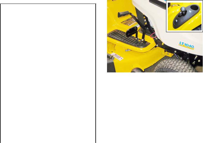
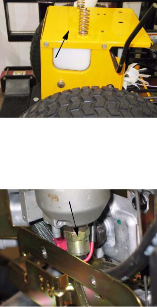
1.10.A Two-belt CVT system driving an MTD singlespeed transaxle is presently used only on the LT1040 model. This system can be distinguished by the gear selector (F-N-R) on the left rear fender, and the simple drive pedal.
See Figure 1.10.
Figure 1.10
1.11.A similar two-belt CVT system was employed to drive a heavy-duty transaxle in some 2002 and 2002 models having two forward speed ranges. These are easy to identify by the presence of the gear selector lever between the operators knees rather than on the fender.
1.12.All CVT driven 1000 and 1500 Series tractors have a gear selector lever and a drive pedal on the right side, near the brake pedal.
1.13.All Hydrostatic transaxles on the 1000 and 1500 Series are operated by a rocker pedal on the right side, near the brake pedal.
1.14.A Hydro-Gear 310-0510 hydrostatic transaxle is used on LT models having 20” rear tires. Hydrostatic transaxles have a rocker pedal to control forward and reverse direction and speed.
2
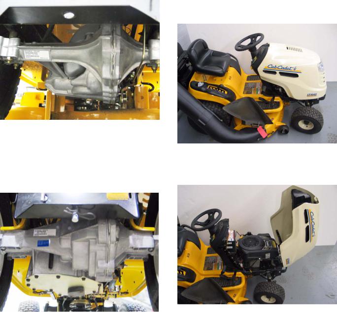
1.15.A Hydro-Gear 314-0610 hydrostatic transaxle with a different final drive ratio is used on LT models having 22” rear tires. Hydrostatic transaxles have a rocker pedal to control forward and reverse direction and speed. See Figure 1.15.
Figure 1.15
1.16.A Hydro-Gear 320-3000 hydrostatic transaxle is used on GT designated models. This is a substantially heavier duty IHT than the one used in the LT models. Hydrostatic transaxles have a rocker pedal to control forward and reverse direction and speed. See Figure 1.16.
Figure 1.16
Series 1000 and 1500
2.NEW HOOD DESIGN
2.1.Early 1000 and 1500 Series tractors used a variety of steel hoods and side panels. Later ones resembled those used on the 2000 and 2500 Series tractors.
2.2.The hood presently used on the 1000 series tractors is a molded 1-piece design. See Figure 2.2.
Figure 2.2
2.3.The 1000 Series hood opens from the back. See Figure 2.3.
Figure 2.3
3
Series 1000 and 1500
2.4.The 1000 Series hood can be easily removed: See Figure 2.4.
Figure 2.4
•Disconnect the headlight wires
•Release the retaining springs
•Align the bolts in the hood with the slots in the hinge.
•Lifting the hood off of the tractor.
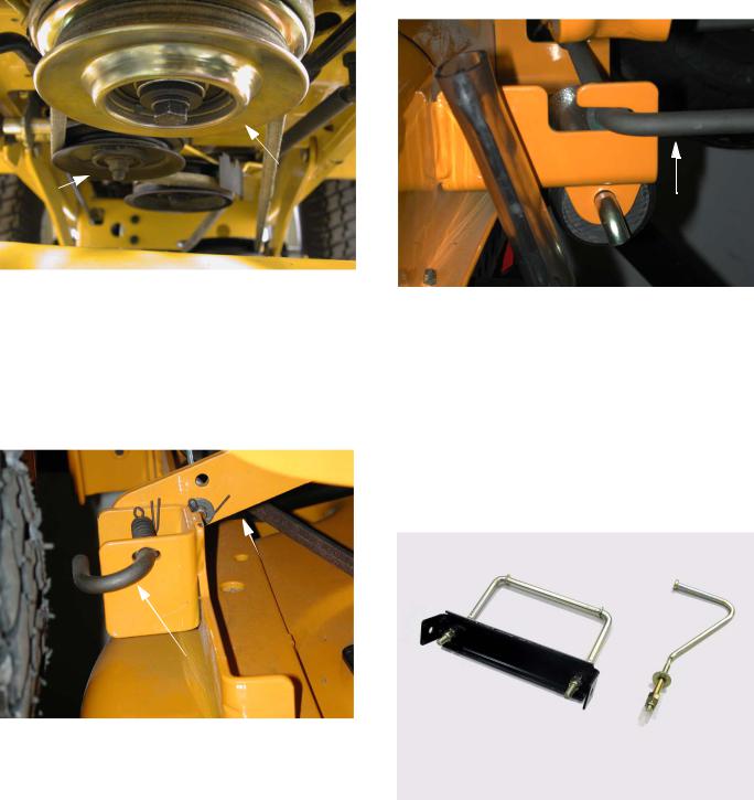
2.5.The hood used on the 1500 Series tractors for 2005 and 2006 is more substantial than that used on the 1000 Series. It is a one-piece molded design very similar to the one used on the much larger 5000 and 6000 series tractors. See Figure 2.5.
•A pair of gas charged cylinders provide lift assist. See Figure 2.5.
Gas lift Cylinders
Pivot Rod
Figure 2.5
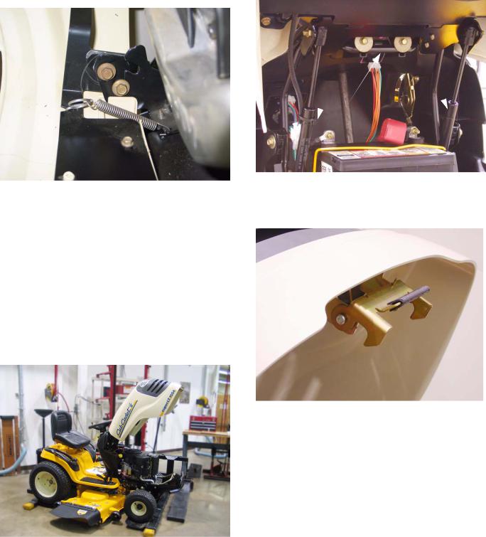
2.6.A new spring-loaded latch was added to hold the hood closed. See Figure 2.6.
Figure 2.6
Figure 2.5
•It opens from the front.
4
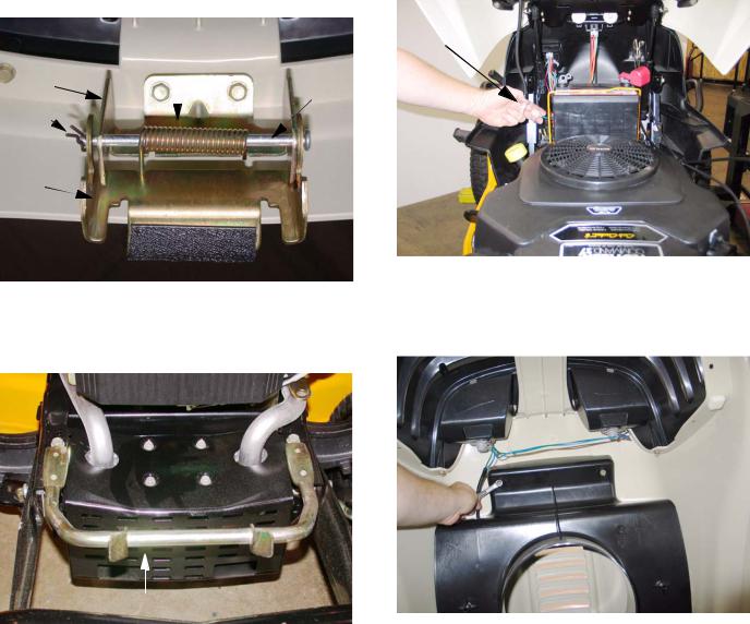
2.7.A torsion spring keeps the latch secure until the lower pivot latch is intentionally pulled up, to open the hood. See Figure 2.7.
Torsion Spring
Upper |
|
Pivot |
|
||
Pivot |
|
|
|
Rod |
|
Latch |
|
|
|
|
|
Cotter |
|
|
Pin |
|
|
Lower |
|
|
Pivot |
|
|
Latch |
|
|
Figure 2.7
2.8.The hood latches to a sturdy rod that is mounted
to the front of the frame. |
See Figure 2.8. |
Hood Latch Rod
Figure 2.8
3.HOOD PANEL REMOVAL: 1500 SERIES
NOTE: Use this procedure if the hood alone is to be removed. Typical reasons might include replacement because of damage to the hood, or to ease access for other service.
3.1.Disconnect ground cable from battery using a 7/16” wrench.
Series 1000 and 1500
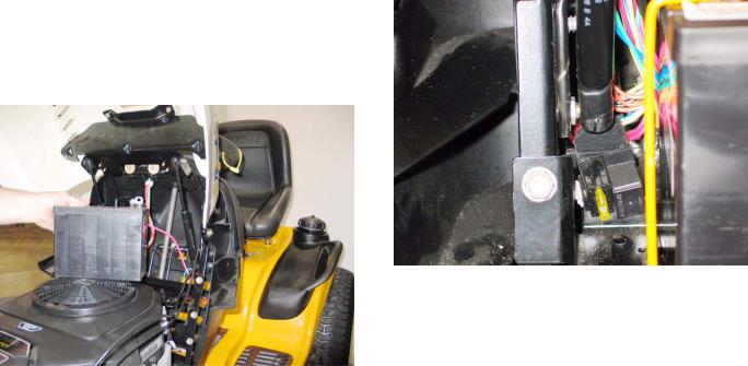
3.2.Disconnect headlight harness (plugged secured to hood lift cylinder). See Figure 3.2.
Headlight
Harness
Figure 3.2
3.3.Remove the air deflector baffle using a 3/8”
wrench. |
See Figure 3.3. |
Figure 3.3
3.4.Support the hood as it is being loosened.
3.5.Separate hood from hinge using a 3/8” wrench.
3.6.Lift hood off of tractor.
5
Series 1000 and 1500
4.HOOD AND HINGE REMOVAL: 1500 SERIES
NOTE: Use this procedure for more extensive repairs. Typical reasons may include dash panel removal, or the need for more working room than simply removing the hood will provide.
4.1.Remove the battery: See Figure 4.1.
4.8.Hood installation notes: See Figure 4.8.
Figure 4.1
•Disconnect the negative battery cable (black) first, using a 7/16” wrench.
•Disconnect the positive battery cable (red) using a 7/16” wrench.
•Remove the battery hold-down.
•Lift the battery from the tractor.
4.2.Disconnect the headlight harness. (Plug secured to the hood lift cylinder).
4.3.Support the hood with an improvised prop-rod to prevent damage.
4.4.Remove screws holding hinge support bar to dash support using a 1/2” wrench.
4.5.Disconnect and remove the hood lift cylinders using a small straight-blade screwdriver.
4.6.Remove screws & flat washers holding hinge support bar to dash panel using a 3/8” wrench.
4.7.Lift hood and hinge assembly off of the tractor, and remove it to a safe place.
Figure 4.8
•Position the hinge support bar over the two spacers that partially cover the threads of the balls that the that hood support struts attach to. The slots in the ends of the bar will fit over the spacers.
•Support the hood with an improvised prop rod.
•Install the screws that hold the hinge support bar to the dash support and instrument panel.
•Snap the hood support cylinder into place, and remove the prop rod.
•The remainder of the installation process is simply the reversal of the removal steps.
6
5.REAR FENDER REMOVAL
5.1.It is necessary to remove the fender assembly for access to the following service areas: See Figure 5.1.
Figure 5.1
•Fuel tank (hydrostatic drive riders)
•Lift-shaft assembly (except bushings)
•Deck lift cable removal
•Wiring harness inspection or removal
•Dash panel removal
•Traction drive belt idler pulley removal
•Traction drive belt tension arm removal
NOTE: At first-glance, fender removal appears to be a substantial job. Skilled mechanics can typically remove the fenders from a 1000 Series Cub Cadet tractor in about 15 minutes, with an equal amount of time required for installation.
5.2.Disconnect the ground cable from the negative battery post using a 7/16” wrench.
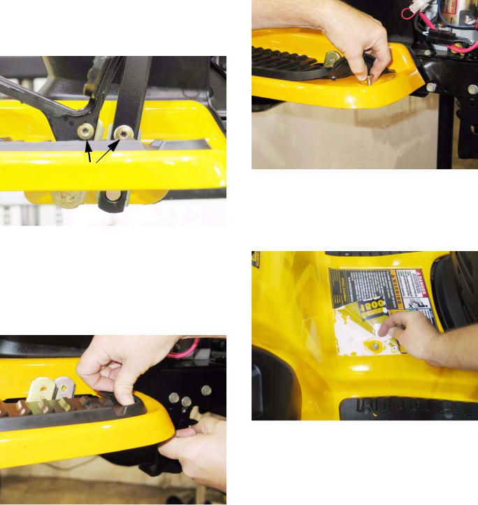
5.3.Remove the cutting deck from the tractor.
Series 1000 and 1500
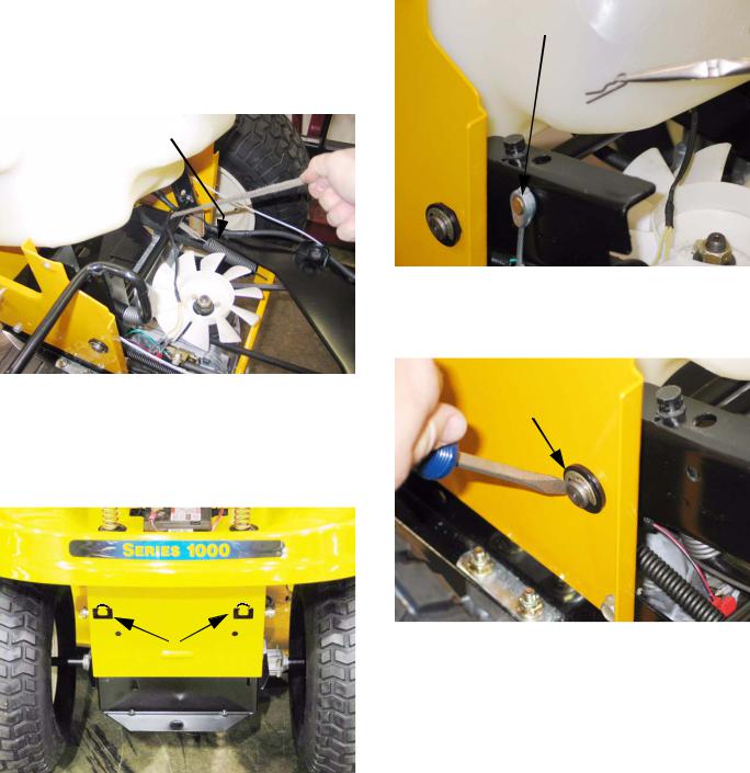
5.4.Remove the rubber grip from the cutting deck height control handle atop the right rear fender. See Figure 5.4.
Figure 5.4
5.5.Disconnect the two yellow wires from the seat safety switch mounted to the left side seat bracket. See Figure 5.5.
Safety Switch Connectors
Figure 5.5
5.6.Release the gold colored extension spring from the left side seat bracket using a length of starter rope or a spring removal tool.
•gold colored spring: left seat bracket
•red spring: right seat bracket
•Only the gold colored spring must be removed because it blocks access to the bolts that hold the seat bracket to the frame.
7
Series 1000 and 1500
5.7.Remove the four bolts that hold the seat brackets to the frame using a 1/2” wrench.
5.8.Remove the seat to a safe location.
5.9.Remove the hydro control pedal (or speed control pedal on CVT equipped models) using a T- 40 driver. See Figure 5.9.
T-40 Screws
Figure 5.9
5.10.Remove the brake pedal using a T-40 driver (upper screw) and a 9/16” wrench (lower screw).
5.11.Remove the nuts from the carriage bolts that secure the front edge of each running board to the frame bracket that supports it.
See Figure 5.11.
Figure 5.11
•Apply thumb pressure to the rubber foot pad, directly above the nut / carriage bolt to hold the square boss on the nut into the bracket, to prevent rotation.
5.12.Peel-back the rubber foot pad to reach and remove the carriage bolt. See Figure 5.12.
Figure 5.12
5.13.Carefully peel-up each rear corner of the larger instruction label located between the foot pads, revealing two screws that hold the fender assembly to the frame. See Figure 5.13.
Figure 5.13
NOTE: If the previous steps are done with care, the label can be reapplied, using some spray-on contact adhesive if necessary.
•If the label shows signs of becoming damaged by the peeling-back process, it should be replaced during reassembly.
•To identify and order a replacement label, note the number printed on the lower right corner of the label (“S32484 AC” typical). That number, with a 777 prefix (777-S32484 AC) is usually the part number of the label.
8
5.14.Remove the two screws that were revealed by peeling-back the label. This can be done using a 3/8” wrench. See Figure 5.14.
Figure 5.14
5.15.Remove the fuel filler cap.
5.16.Lift the fenders off of the tractor, maneuvering them to clear the cutting deck height control lever. See Figure 5.16.
Series 1000 and 1500
•When installing a large panel, start all of the threaded fasteners, then go back and tighten each after the panel is in position.
•Test the operation of all controls and safety features in a safe place, free of obstacles and bystanders before returning the tractor to service.
6.FUEL SYSTEM
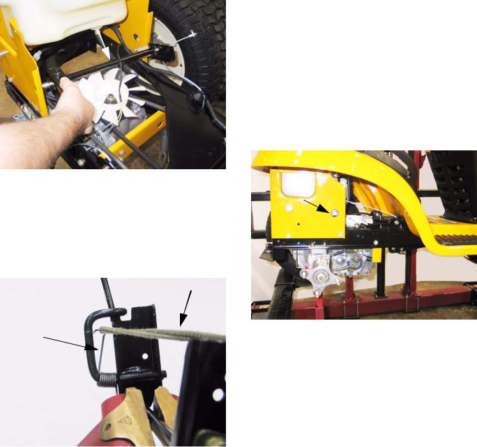
6.1.While the 1000 and 1500 Series tractors are built on the same frame, the fuel systems differ substantially in layout.
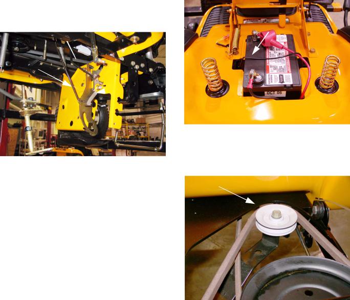
6.2.The 1000 Series tractors have the fuel tank beneath the hood, with the battery located under the seat. See Figure 6.2.
Figure 5.16
5.17.Remove the fenders to a safe place.
5.18.Replace the fuel filler cap.
5.19.Installation notes:
•Confirm that the seat safety switch wires are accessible before securing the fender.
•144 in-lbs is adequate tightening torque for the 5/16”-18 screws and bolts removed in this procedure. (1/2” wrench or T-40 driver)
Figure 6.2
6.3.This positioning is necessary to provide easy service access to the CVT drive system used on the 1000 series tractors. The rear mounted battery, and the tray that supports it are easily removable.
6.4.The battery of the 1500 Series tractor is located under the hood, with the fuel tank mounted under the rear fenders.
9
Series 1000 and 1500
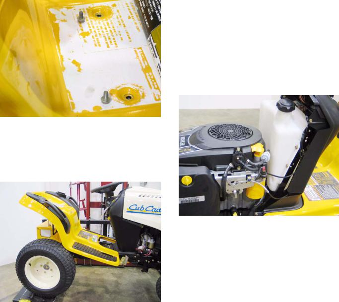
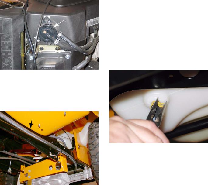
6.5.On current models of the 1000 and 1500 Cub Cadet, the fuel is moved from the tank to the car-
buretor by a vacuum-driven fuel pump that is mounted to the engine. See Figure 6.5.
Fuel Pump
Figure 6.5
6.6.The fuel line runs from a barbed fitting on the bottom of the fuel tank to the fuel pump.
6.7.The 1500 series fuel line should be routed as
shown. |
See Figure 6.7. |
Fuel Line
Figure 6.7
6.8.The fuel cap is vented.
•There are a few non-vented fuel caps that will fit the filler neck of the 1000 and 1500 Series tractor.
•Non-vented caps are used on the Cub Cadet Big Country line of utility vehicles.
•Use of a non-vented cap on a 1000 or 1500 Series tractor will cause fuel supply issues.
6.9.In the event that it is necessary to remove the fuel tank, begin by removing the fenders as described in the REAR FENDER REMOVAL section of this manual.
6.10.Make provisions for draining any fuel that remains in the gas tank: 24” of 1/4” fuel line, and a suitable catch pan will be sufficient.
6.11.Pinch the fuel line about 6” from the fuel tank to prevent the line from emptying (unless it needs to be drained or replaced).
•Position the catch pan under the fitting on the fuel tank.
•Have the extra length of fuel line handy.
6.12.Remove the hose clamp that secures the fuel line to the fitting on the gas tank.
See Figure 6.12.
Figure 6.12
6.13.Quickly pull the fuel line off of the fitting, and replace it with the extra hose. Direct the hose into the catch pan.
6.14.When the tank is empty, dispose of any unusable fuel in a safe and responsible manner.
10
6.15.Remove the plate that supports the seat brackets using a 1/2” wrench. See Figure 6.15.
Seat Bracket Plate
Figure 6.15
6.16. Lift the fuel tank out of the tractor.
7.FUEL SHUT-OFF SOLENOID
7.1.In all models of the 1000 and 1500 Series Cub Cadet riders, there is a fuel shut-off solenoid mounted to the carburetor. See Figure 7.1.
Fuel Shutoff Solenoid
Figure 7.1
7.2.The fuel shut-off solenoid is a valve that is actuated by an electric coil.
•The fuel shut-off solenoid helps prevent “afterboom” when a hot engine is turned-off.
•The solenoid has power when the key is in the run position and the safety switches on the tractor do not sense any unsafe conditions. When it has power, the solenoid opens, allowing fuel to reach the carburetor.
Series 1000 and 1500
•When the solenoid does not have power, it closes, stopping the flow of fuel.
•The solenoid usually emits an audible “click” when power is applied or discontinued.
•If the solenoid does not click, it is not working. If it does click, it cannot be assumed to be working properly.
8.FUEL RELATED NO-START ISSUES
8.1.The leading industry cause of no-start and engine performance problems is stale or outdated fuel.
•In temperate regions of the country, fuel purchased during the summer may not be volatile enough to ignite during the winter months.
•Similarly, “Winter” fuel may be cause performance issues if used into the summer months. The gasoline companies taylor the contents of their fuel blends to optimize performance, taking climate and geography into account.
•As fuel goes stale, the lighter end hydrocarbons (more volatile elements) tend to evaporate, leaving the fuel less volatile.
•In extreme cases, semi-solid residue will accumulate, damaging the fuel system.
•If a piece of equipment will sit unused during the dormant season, the fuel system should be drained completely, or preservative should be added to the fuel according to the preservative manufacturer’s instructions.
8.2.Alcohol content of the fuel should not exceed 10%.
•Small amounts of ethanol are fairly common in fuel.
•Methanol is more destructive than ethanol, and should be avoided.
•Alcohol absorbs water. Fuel that contains alcohol will also contain a certain amount of water. The water will corrode any metallic parts of the fuel system, and may cause freezing damage in low temperatures.
•Products that purport to “dry” the fuel system are generally isopropyl alcohol. The object is to resuspend the water that has settled out of the alcohol the fuel already contains.
11
Series 1000 and 1500
•Ether-based starting fluids should not be used, and may void engine warranties if their use is detected.
9.MUFFLER REMOVAL
NOTE: There are a variety of mufflers on this series of tractor depending on the year and engine of the unit. this chapter will cover a few different mufflers to give you the basics of muffler removal on this series.
NOTE: For all tractors, remove the bumper first.
•On units with side panels:
9.1.Remove the hood, side panels and grill.
NOTE: Make sure to disconnect the headlight harness when you remove the grill and side panels.
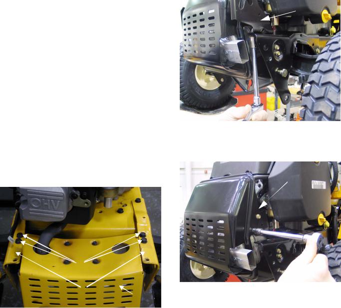
9.2.Remove the self tapping hex cap screws securing the front frame assembly to the muffler shield and muffler using a 1/2" socket. See Figure 9.2.
Hex Cap Screws
Frame
Muffler Shield
Figure 9.2
9.3.Remove the muffler and guard.
NOTE: Muffler slides off of the exhaust pipe. It is NOT fastened to the pipe.
9.4.Remove the four screws in the top of the muffler guard. the muffler and muffler guard will now separate.
9.5.Reassemble in reverse order.
•1000 Series with one piece hood.
9.6.Remove hood as shown in section 2.
9.7.Remove both hinge brackets. See Figure 9.7.
Hinge Bracket
Figure 9.7
9.8.Remove the four screws in the sides of the muffler guard. Slide the muffler and muffler guard off of the exhaust pipe(s). See Figure 9.8.
Muffler Guard
Figure 9.8
NOTE: You may have the tail pipe sticking out of the left side. If so slide the guard off of it first.
12
9.9.Remove the four screws going through the muffler support brackets into the muffler mounting bracket. See Figure 9.9.
Muffler Support Bracket
Figure 9.9
9.10.The muffler will now slide off of the exhaust pipe(s).
9.11.Remove the screws in the muffler mounting brackets and lift the brackets off of the muffler.
9.12.Reassemble in reverse order.
• 1500 with one piece hood:
9.13.Open hood.
9.14.Remove bumper
9.15.Remove the two clevis pins in the deck front stabilizer bracket.
Series 1000 and 1500
9.16.Remove the four screws holding the muffler guard to the front muffler support brackets. See Figure 9.16.
Remove these hex screws. (two on each side)
Figure 9.16
NOTE: The rear two screws will be accessible from the top. the front two screws will be accessible from the bottom.
9.17.Slide the muffler and muffler guard off of the exhaust pipe(s).
9.18.Remove the four screws in the top of the muffler guard. Lift the muffler guard off of the muffler.
9.19.Reassemble in reverse order.
10.CUTTING DECK REMOVAL
10.1.Place the PTO switch in the off position.
10.2.Lower the lift lever to the lowest setting.
13
Series 1000 and 1500
10.3.Remove the PTO belt from electric PTO clutch. See Figure 10.3.
10.7.Slide the deck forward and release the front stabilizer rod. DO NOT DROP the deck to the ground. See Figure 10.7.
Idler |
Electric PTO |
clutch |
|
(earlier production) |
|
Figure 10.3
NOTE: On some models you will need to remove the belt guide first.
NOTE: On earlier production models you need to slip the belt off of the idler pulley before you remove the belt from the PTO clutch.
10.4. Pull the rear deck support pins outward from the deck lift arms. See Figure 10.4.
Lift arm
Deck support pin
Figure 10.4
10.5.Pivot the deck support pins to the rear.
10.6.Raise the lift lever to the highest setting. This will raise the lift arms up and out of the way of the deck assembly.
Front stabilizer rod
Figure 10.7
10.8.Slide the deck toward the right side of he tractor and remove it from under the tractor.
CAUTION: Remove the deck stabilizer assembly from the tractor prior to moving the unit.
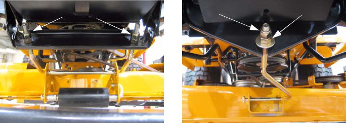
NOTE: Depending on the model and deck, some units have a J-bolt for the front stabilizer bar instead of the U-bolt. On those units you can line up the coined spot stamped in the middle of the bolt with the slot in the bracket and slide it off. See Figure 10.8.
U-Bolt Stabilizer
J-Bolt Stabilizer
Figure 10.8
14
11.DECK LIFT SHAFT ASSEMBLY
11.1.If the deck lift shaft itself requires removal, first remove the cutting deck.
11.2.Remove the fenders as described in the FENDER REMOVAL section of this manual.
11.3.Disconnect the deck lift assist spring that extends from the deck lift shaft to the transaxle torque bracket using a length of starter rope or a spring tool. See Figure 11.3.
Deck Lift Assist Spring 
Figure 11.3
11.4.On models built in 2004 and prior, the lift assist springs extend rearward to a pair of openings with mounting tabs in the back surface of the upper frame. See Figure 11.4.
Mounting Tabs
Figure 11.4
11.5.Unbolt the seat bracket mounting plate from the frame (4 screws) using a 1/2” wrench. This will allow the fuel tank to be lifted slightly for clearance, but the tank need not be removed.
Series 1000 and 1500
11.6.With the deck height control lever all the way forward, remove the hairpin clips that secure the deck lift cables to the arms on the deck lift shaft. See Figure 11.6.
Deck Lift Cable
Figure 11.6
11.7.Remove the E-clip from each end of the lift-shaft. See Figure 11.7.
E-clip
Figure 11.7
11.8.Pry the bushings that support the lift shaft out of the frame.
15
Series 1000 and 1500
11.9.Slide the lift shaft assembly to the right, providing clearance to remove the left end of the shaft from the frame. See Figure 11.9.
Lift Shaft
bushing, it should be a dry graphite or PTFE based lube.
•Replace the bushings an E-clips if they show signs of wear.
•Reverse the removal process to install the lift shaft.
•Connect the cables and install the bushings prior to connecting the tension spring between the lift shaft arm and the transaxle torque bracket.
12.LIFT SHAFT BUSHINGS
12.1.The most common item on the lift shaft assembly to require service is likely to be the bushings that support the shaft. These bushings are visible beneath the fender. See Figure 12.1.
Figure 11.9
11.10.Slide the lift shaft back to the left to remove it from the tractor.
11.11.On the bench, relieve torsion spring pressure between the lift shaft and the lever that controls it using a length of starter rope. See Figure 11.11.
Starter Rope
Torsion Spring
Figure 11.11
11.12.Rotate the lever to align the coined “ears” with the slots in the lift shaft arm, allowing separation of the lever from the arm.
11.13.Assembly notes:
•Because of the dusty environment that many mowers operate in, grease applied to this bushing may accelerate wear rather than prevent it. If any lubricant is used between the shaft and the
Bushing
Figure 12.1
12.2.When performing normal maintenance that requires deck removal, inspect the lift shaft bushings while the weight of the deck is removed from them.
•These bushings are normal wear items.
•Grasp the lift shaft and apply up and down force.
•Watch for shaft motion within the bushings.
•Larger decks, such as the 50” and 54” (P and K) decks will place a greater load on the bushings.
•Worn bushings may cause deck leveling issues.
12.3.To replace the bushings, the weight of the deck should be removed from the deck lift cable. Remove the cutting deck before attempting to remove the bushings.
16
12.4.Disconnect the deck lift assist spring that extends from the deck lift shaft to the transaxle torque bracket using a length of starter rope or a
spring tool. |
See Figure 12.4. |
Deck Lift Assist Spring
Figure 12.4
12.5.Remove the E-clip that holds each shouldered hex bushing into the tractor frame. Replace one bushing at a time.
12.6.Pry the worn bushing out of the hole.
12.7.Clean any dirt or corrosion from the surface of the lift shaft that contacts the bushing.
NOTE: Because of the dusty environment that many mowers operate in, grease applied to this bushing may accelerate wear rather than prevent it. If any lubricant is used between the shaft and the bushing, it should be a dry graphite or PTFE based lube.
12.8.Insert the new bushings, and secure them with the E-clips.
12.9.Check deck levelness, and make any necessary adjustments before returning the tractor to service.
13.DECK LIFT CABLES AND PULLEYS
NOTE: The deck lift cables and pulleys can be replaced without removing the rear fenders.
13.1.To remove the deck lift cables, remove the cutting deck.
13.2.Lift and safely support the rear of the tractor.
Series 1000 and 1500
13.3.Remove the rear tires using a 3/4” wrench. See Figure 13.3.
Figure 13.3
13.4.Remove the handle from the rear fenders using a 3/8” wrench. The screws are accessible from inside the rear fender. See Figure 13.4.

 Handle Screws
Figure 13.4
17
Series 1000 and 1500
13.5.Remove the notched plate that the deck height control lever seats against in the fender, using a 1/2” socket. See Figure 13.5.
Figure 13.5
13.6.Push the deck height control lever as far forward as it will go, and secure the lever in that position.
13.7.Remove the pulley that carries the deck lift cable using a 1/2” wrench and a 5/8” wrench.
13.8.Remove the E-clip from the same end of the lift shaft that the cable is being removed from. This will allow the lift shaft to be pushed-in slightly, providing clearance for the pin.
13.9.Remove the hairpin clip that secures the pin on the top end of the cable to the arm on the deck lift shaft. See Figure 13.9.
Deck Lift Cable 
Figure 13.9
NOTE: Early models used a removable clevis pin. Current production cables have captive pins.
13.10.Remove the hairpin clip that secures the pin to the lift arm, and remove the cable.
13.11.Installation notes:
•Reverse the removal process to install the cables and pulleys.
•Because of the dusty environment that many mowers operate in, grease applied to the cable or pulley may accelerate wear rather than prevent it. If any lubricant is used on the pulley, it should be a dry graphite or PTFE based lube.
•Replace the pulleys and cables if they show signs of wear.
•Check deck level before returning the tractor to service.
•Tighten fasteners to the following torques:
Lug nuts |
75ft-lbs (Nm) |
Screws, handle to fender |
60 in-lbs (Nm) |
Screws, plate to fender |
144in-lbs (Nm) |
Shoulder bolts, pulley |
144 in-lbs (Nm) |
14.LEVELING THE CUTTING DECK
NOTE: Prior to leveling the mowing deck, perform the following steps:
•Check the tire pressure. The front tires will be approximately 14 PSI, and the rear tires will be approximately 10 PSI.
•Place the tractor on a level surface.
•Depress and lock the parking brake.
•Place the cutting deck in cutting position 3 or 4.
SIDE TO SIDE ADJUSTMENT
IMPORTANT: The cutting deck must be even side to side.
18
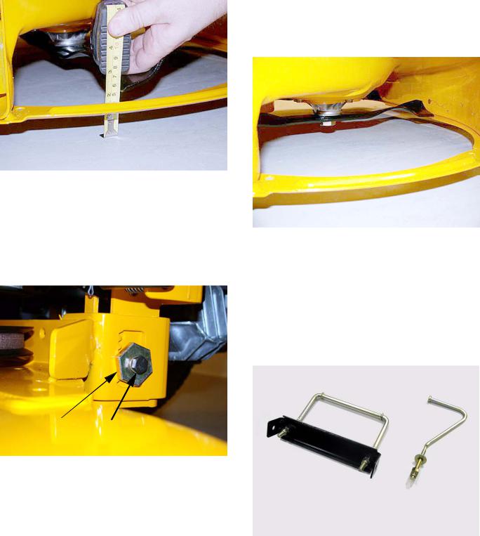
14.1.Using a work glove or rag, rotate the blades until they are cutting edge tip to cutting edge tip (perpendicular) to the tractor. See Figure 14.1.
Figure 14.1
14.2.Measure the outer blade tips to ground. Both measurements taken should be equal.
NOTE: If an adjustment is needed, perform the following steps:
14.3.Loosen (DO NOT REMOVE) the hex cap screw on the left deck hanger bracket using a 1/2” and a 3/4” wrench. See Figure 14.3.
Adjustment Gear Hex Cap Screw
Figure 14.3
14.4.Rotate the 3/4” deck adjustment gear right or left until the deck is level side to side and both blade tips to ground are equal in measurement.
14.5.Retighten the hex cap screw on the left deck hanger using a 1/2” and a 3/4” wrench when the proper adjustment has been achieved.
Series 1000 and 1500
FRONT TO REAR ADJUSTMENT
IMPORTANT: The front of the deck will be between 1/4” and 3/8” lower in the front than the rear of the deck.
14.6.Using a work glove or a rag, rotate the blades until they are parallel with the tractor frame. See Figure 14.6.
Blades parallel with frame
Figure 14.6
14.7.Measure the front blade tips to the ground.
14.8.Measure the rear blade tips to the ground.
14.9.Make certain the front blade tips are 1/4” to 3/8” lower than the rear blade tips.
NOTE: If an adjustment is needed, perform the following steps:
14.10.There two types of stabilizer rods. A U-bolt type and a J-bolt type. See Figure 14.10.
U-Bolt Stabilizer
J-Bolt Stabilizer
Figure 14.10
19
Series 1000 and 1500
•For the U-bolt style:
14.11.Loosen both lock nuts securing the adjustment nuts on the front of the deck stabilizer bracket using a two 3/4” wrenches.
 Lock Nuts

 Adjustment Nuts

Figure 14.11
14.12.Locate both adjustment nuts on the front side of the deck stabilizer bracket. See Figure 14.11.
14.13.Tighten both nuts to raise the front of the deck or loosen both nuts to lower the front of the deck using a 3/4” wrench.
NOTE: Make sure you count the number of turns you put on the first nut and put the same number on the second nut. both nuts must be moved equally.
14.14.Retighten both lock nuts to jam the adjustment nuts into position when the proper adjustment has been achieved.
•For the J-bolt Style:
14.15.The J-bolt style stabilizer is adjusted in a similar fashion. Loosen the single lock nut away from the adjustment nut using two 3/4” wrenches.
Lock Nut |
Adjustment Nut |
Figure 14.15
14.16.To lower the front of the deck loosen the adjustment nut on the J-bolt. To raise the front of the deck tighten the lock nut. Tighten the lock nut against the adjustment nut when finished.
15.DASH PANEL REMOVAL
15.1.Remove fender, as described in the FENDER REMOVAL section of this manual.
15.2.For the 1500 remove the hood and battery, as described in the HOOD REMOVAL section of this manual.
•For the 1000 remove the fuel tank by first removing the fuel cap. place a piece of plastic over fuel tank opening and put fuel cap back on.
•Remove the four 1/2” screws holding the fuel tank in place.
•Lift the fuel tank and place on top of engine or clamp the fuel line and remove it from the fuel pump and remove fuel tank from unit.
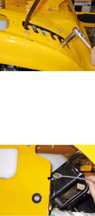
15.3. Pry the cap off the center of the steering wheel.
20
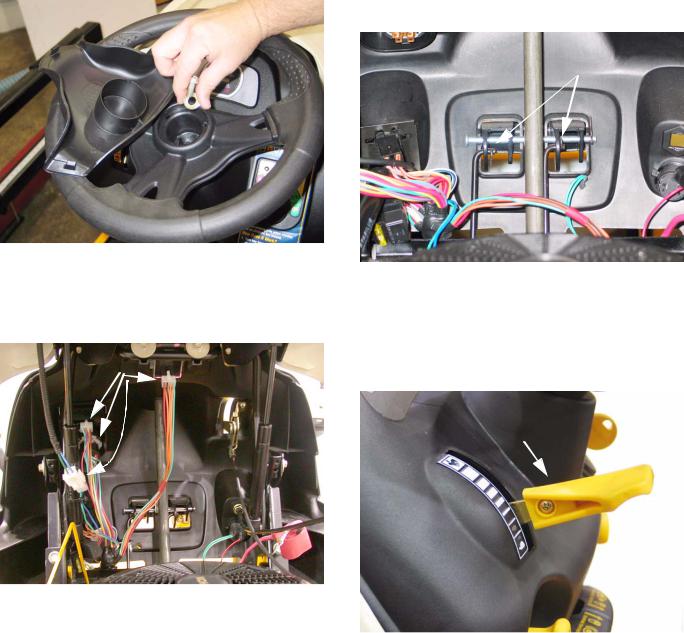
15.4.Remove the steering wheel from the steering shaft using a 1/2” wrench. See Figure 15.4.
Figure 15.4
15.5.Disconnect the following dash-mounted electrical devices by unplugging the molded connectors: See Figure 15.5.
Molded connectors
Figure 15.5
NOTE: Image shows 1500 dash. 1000 series dash components are in a similar location.
•Key switch and OCR module
•PTO Switch
•Hour meter / Monitor
•Accessory power port - if present.
Series 1000 and 1500
15.6.Disconnect the rods that connect the Park Brake and Cruise Control mechanisms to the levers on the dash that control those features by removing the hairpin clips. See Figure 15.6.
Hairpin clips
Figure 15.6
15.7.Remove the knob from the throttle lever using a phillips head screwdriver, then remove the screws that hold the throttle assembly to the dash panel. See Figure 15.7.
Throttle
Lever
Figure 15.7
15.8.On models with a separate choke cable, disconnect the choke cable at the engine end. If the technician prefers, they may also choose to disconnect the throttle cable at the engine end.
15.9.Remove the remaining screws that hold the dash panel to the tractor, and remove the dash.
•Two socket-head cap screws (T-40) at each side of the base of the dash panel (four total).
21
Series 1000 and 1500
•Two hex-head cap screws holding the rear flange of the dash to the frame (1/2” wrench)
•Two hex-head cap screws holding the top of the dash to the dash support (3/8” wrench).
See Figure 15.9.
Hex-head cap screw
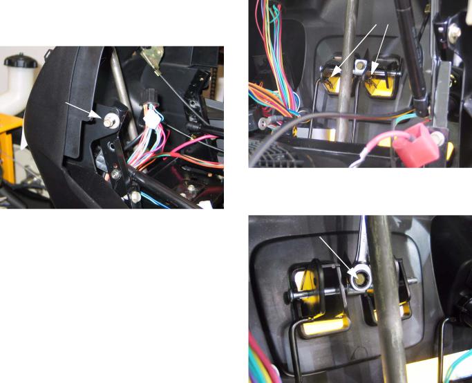
16.4.Remove the hair pin clips holding the linkages to the levers in the dash. See Figure 16.4.
Hairpin Clips
Figure 15.9
15.10.Reverse the removal process to install the dash panel.
•Test the operation of all safety features in a safe area that is clear of obstacles and bystanders before returning the tractor to service.
•Test the operation of all controls in a safe area that is clear of obstacles and bystanders before returning the tractor to service.
16.CRUISE CONTROL AND PARK BRAKE LINKAGES
16.1.Open the hood.
16.2.On the 1000 series you need to remove the fuel tank. on the 1500 series you need to remove the battery.
16.3.The procedure for removing the park brake linkage and the cruise control linkage is the same. you can remove both at the same time.
Figure 16.4
16.5.Remove the screw holding the pivot rod in place. See Figure 16.5.
Pivot Rod Hex Screw
Figure 16.5
16.6.Remove the hair pin clip in the pivot rod.
16.7.Work the pivot rod out. sliding it out to the right. the levers will fall out as the rod clears them.
16.8.Raise the unit off of the ground.
16.9.Remove the brake and drive pedals.
22

16.10.Remove the cotter pins in the brake pedal shaft and the drive pedal shafts. See Figure 16.10..
Cotter Pins 
Figure 16.10
16.11.Slide the drive pedal to the right. The inboard bushing and washer can now be removed. Continue working the drive pedal shaft to the right and slip it out of the unit.
16.12.Remove the hair pin clip in the brake rod and disconnect it from the brake pedal shaft.
16.13.Remove the return spring from the brake pedal shaft.
16.14.Slide the brake pedal shaft to the right and remove the inboard bushing and washer. Continue sliding the brake pedal shaft to the right and work it off of the unit.
16.15.Remove both drag links from the tractor.
NOTE: Make sure to keep the drag links separate so the you know which one is for the left and which one is for the right. they are not marked and they are not interchangeable.
Series 1000 and 1500
16.16.Remove the lock nut from the bottom of the steering shaft. Then slide off the steering shaft gear. See Figure 16.16.
Lock Nut
Hex Nut
Figure 16.16
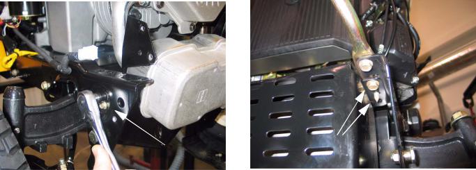
16.17.Reaching up through the opening where the pedal shafts were, place a 9/16” wrench on the head of the bolt located in the center rear of the subframe. Using a 9/16” socket, remove the nut. See Figure 16.16.
NOTE: There is a sleeve on this bolt that acts as a spacer between the sub-frame and frame. Be aware of this sleeve when you lower the subframe in a later step.
16.18.There are four screws holding the subframe to the tractor.Two on each side. Loosen the two front screws and remove the two rear screws. See Figure 16.18.
Loosen these two.
Sub Frame Hex Screws
Remove these two.
Figure 16.18
23
Series 1000 and 1500
16.19.Pivot the subframe down. Be careful of the spacer on the bolt and the hex flange bushing for the steering shaft, they will fall out.
16.20.You now have access to the cruise linkage and cam lock. You also have access the park brake linkage and locking plate. See Figure 16.20.
Cruise Control Rod.
Parking Brake Rod
 Cam Lock
17.3.Remove the battery hold-down, remove the battery and the battery tray. See Figure 17.3.
Battery Hold Down
Figure 16.20
16.21.Remove the hair pin clips on the linkages. Remove the linkages.
16.22.Remove the nut and bolt holding the cruise cam and/or the park brake locking plate.
16.23.Reassemble in reverse order.
CAUTION: Make sure the linkage rods are routed properly before you swing the subframe
17.TRACTION DRIVE BELT REPLACEMENT: CVT
NOTE: There are two drive belts in the CVT system. Because they work together on the variable speed pulley, wear to one belt effects the performance of the other belt. It is strongly recommended that the belts be replaced as a set.
17.1.Remove the cutting deck from the tractor.
17.2.Tilt-up the seat and disconnect the battery cables (ground cable first) using a 7/16” wrench.
Figure 17.3
17.4.Pull the upper drive belt tensioner pulley rearwards to provide slack in the belt, and roll the belt off of the tensioner pulley. See Figure 17.4.
Tensioner pulley
Figure 17.4
17.5. Carefully release the tensioner pulley.
24
Loading...