


Professional Shop Manual
P90 Series Vertical Shaft Engines
NOTE: These materials are for use by trained technicians who are experienced in the service and repair of outdoor power equipment of the kind described in this publication, and are not intended for use by untrained or inexperienced individuals. These materials are intended to provide supplemental information to assist the trained technician. Untrained or inexperienced individuals should seek the assistance of an experienced and trained professional. Read, understand, and follow all instructions and use common sense when working on power equipment. This includes the contents of the product’s Operators Manual, supplied with the equipment. No liability can be accepted for any inaccuracies or omission in this publication, although care has been taken to make it as complete and accurate as possible at the time of publication. However, due to the variety of outdoor power equipment and continuing product changes that occur over time, updates will be made to these instructions from time to time. Therefore, it may be necessary to obtain the latest materials before servicing or repairing a product. The company reserves the right to make changes at any time to this publication without prior notice and without incurring an obligation to make such changes to previously published versions. Instructions, photographs and illustrations used in this publication are for reference use only and may not depict actual model and component parts.
© Copyright 2011 MTD Products Inc. All Rights Reserved
Table of Contents
Chapter 1: Introduction |
|
Professional Service Manual Intent . . . . . . . . . . . . . . . . . . . . . . . . . . . . . . . . . . |
. 1 |
Safety . . . . . . . . . . . . . . . . . . . . . . . . . . . . . . . . . . . . . . . . . . . . . . . . . . . . . . . . . |
. 1 |
Fasteners . . . . . . . . . . . . . . . . . . . . . . . . . . . . . . . . . . . . . . . . . . . . . . . . . . . . . . |
3 |
Assembly instructions . . . . . . . . . . . . . . . . . . . . . . . . . . . . . . . . . . . . . . . . . . . . . |
3 |
Model and serial number . . . . . . . . . . . . . . . . . . . . . . . . . . . . . . . . . . . . . . . . . . . |
5 |
Maintenance . . . . . . . . . . . . . . . . . . . . . . . . . . . . . . . . . . . . . . . . . . . . . . . . . . . . |
5 |
Spark plugs . . . . . . . . . . . . . . . . . . . . . . . . . . . . . . . . . . . . . . . . . . . . . . . . . . . . . |
6 |
Air filter . . . . . . . . . . . . . . . . . . . . . . . . . . . . . . . . . . . . . . . . . . . . . . . . . . . . . . . . |
7 |
Oil type and capacity . . . . . . . . . . . . . . . . . . . . . . . . . . . . . . . . . . . . . . . . . . . . . . |
8 |
Changing the oil . . . . . . . . . . . . . . . . . . . . . . . . . . . . . . . . . . . . . . . . . . . . . . . . . |
9 |
Oil filter . . . . . . . . . . . . . . . . . . . . . . . . . . . . . . . . . . . . . . . . . . . . . . . . . . . . . . . |
10 |
Oil pre-screen . . . . . . . . . . . . . . . . . . . . . . . . . . . . . . . . . . . . . . . . . . . . . . . . . . |
10 |
Fuel system . . . . . . . . . . . . . . . . . . . . . . . . . . . . . . . . . . . . . . . . . . . . . . . . . . . . |
11 |
Servicing the fuel system . . . . . . . . . . . . . . . . . . . . . . . . . . . . . . . . . . . . . . . . . |
11 |
Fuel filter . . . . . . . . . . . . . . . . . . . . . . . . . . . . . . . . . . . . . . . . . . . . . . . . . . . . . . |
11 |
Valve lash . . . . . . . . . . . . . . . . . . . . . . . . . . . . . . . . . . . . . . . . . . . . . . . . . . . . . |
12 |
Exhaust system . . . . . . . . . . . . . . . . . . . . . . . . . . . . . . . . . . . . . . . . . . . . . . . . . |
14 |
Cleaning the engine . . . . . . . . . . . . . . . . . . . . . . . . . . . . . . . . . . . . . . . . . . . . . |
14 |
General torque specifications . . . . . . . . . . . . . . . . . . . . . . . . . . . . . . . . . . . . . . |
14 |
Chapter 2: Basic Troubleshooting |
|
Definitions . . . . . . . . . . . . . . . . . . . . . . . . . . . . . . . . . . . . . . . . . . . . . . . . . . . . . |
15 |
Introduction . . . . . . . . . . . . . . . . . . . . . . . . . . . . . . . . . . . . . . . . . . . . . . . . . . . . |
15 |
Steps to troubleshooting . . . . . . . . . . . . . . . . . . . . . . . . . . . . . . . . . . . . . . . . . . |
15 |
Define the problem . . . . . . . . . . . . . . . . . . . . . . . . . . . . . . . . . . . . . . . . . . . . . . |
15 |
Identify factors that could cause the problem . . . . . . . . . . . . . . . . . . . . . . . . . . |
17 |
Repairing the problem . . . . . . . . . . . . . . . . . . . . . . . . . . . . . . . . . . . . . . . . . . . . |
21 |
Prime test . . . . . . . . . . . . . . . . . . . . . . . . . . . . . . . . . . . . . . . . . . . . . . . . . . . . . |
22 |
Leak-down test . . . . . . . . . . . . . . . . . . . . . . . . . . . . . . . . . . . . . . . . . . . . . . . . . |
22 |
Compression test . . . . . . . . . . . . . . . . . . . . . . . . . . . . . . . . . . . . . . . . . . . . . . . |
24 |
PCV testing . . . . . . . . . . . . . . . . . . . . . . . . . . . . . . . . . . . . . . . . . . . . . . . . . . . . |
25 |
Chapter 3: Air Intake System |
|
Air filter . . . . . . . . . . . . . . . . . . . . . . . . . . . . . . . . . . . . . . . . . . . . . . . . . . . . . . . |
27 |
Blower/air filter housing . . . . . . . . . . . . . . . . . . . . . . . . . . . . . . . . . . . . . . . . . . . |
29 |
Carburetor and Insulator . . . . . . . . . . . . . . . . . . . . . . . . . . . . . . . . . . . . . . . . . . |
30 |
I
Chapter 4: The Fuel System and Governor
Inspecting the fuel . . . . . . . . . . . . . . . . . . . . . . . . . . . . . . . . . . . . . . . . . . . . . . . 33
Test fuel for alcohol . . . . . . . . . . . . . . . . . . . . . . . . . . . . . . . . . . . . . . . . . . . . . . 34 Choke/throttle cable adjustment . . . . . . . . . . . . . . . . . . . . . . . . . . . . . . . . . . . . 35
Carburetors . . . . . . . . . . . . . . . . . . . . . . . . . . . . . . . . . . . . . . . . . . . . . . . . . . . . 36
Inspecting the carburetor . . . . . . . . . . . . . . . . . . . . . . . . . . . . . . . . . . . . . . . . . 36 Disassembly and rebuilding the carburetor . . . . . . . . . . . . . . . . . . . . . . . . . . . . 37
Engine speed adjustment . . . . . . . . . . . . . . . . . . . . . . . . . . . . . . . . . . . . . . . . . 41
Afterfire solenoid . . . . . . . . . . . . . . . . . . . . . . . . . . . . . . . . . . . . . . . . . . . . . . . . 42 Testing the afterfire solenoid . . . . . . . . . . . . . . . . . . . . . . . . . . . . . . . . . . . . . . . 44
Governor . . . . . . . . . . . . . . . . . . . . . . . . . . . . . . . . . . . . . . . . . . . . . . . . . . . . . . 46
Governor arm . . . . . . . . . . . . . . . . . . . . . . . . . . . . . . . . . . . . . . . . . . . . . . . . . . 46 Governor shaft . . . . . . . . . . . . . . . . . . . . . . . . . . . . . . . . . . . . . . . . . . . . . . . . . . 48
Governor cup and the governor gear . . . . . . . . . . . . . . . . . . . . . . . . . . . . . . . . 48
Chapter 5: Lubrication
Oil type and quantity . . . . . . . . . . . . . . . . . . . . . . . . . . . . . . . . . . . . . . . . . . . . . 49
Oil dipstick . . . . . . . . . . . . . . . . . . . . . . . . . . . . . . . . . . . . . . . . . . . . . . . . . . . . . 50 Dip stick tube removal . . . . . . . . . . . . . . . . . . . . . . . . . . . . . . . . . . . . . . . . . . . . 50
Lubrication system . . . . . . . . . . . . . . . . . . . . . . . . . . . . . . . . . . . . . . . . . . . . . . 51
Testing the oil Pump . . . . . . . . . . . . . . . . . . . . . . . . . . . . . . . . . . . . . . . . . . . . . 51 Positive crankcase ventilation valve . . . . . . . . . . . . . . . . . . . . . . . . . . . . . . . . . 53
Chapter 6: Starter and Charging Systems
Starter removal . . . . . . . . . . . . . . . . . . . . . . . . . . . . . . . . . . . . . . . . . . . . . . . . . 55
Bench testing the electric starter . . . . . . . . . . . . . . . . . . . . . . . . . . . . . . . . . . . . 56
Rebuilding the starter . . . . . . . . . . . . . . . . . . . . . . . . . . . . . . . . . . . . . . . . . . . . 57 Charging system . . . . . . . . . . . . . . . . . . . . . . . . . . . . . . . . . . . . . . . . . . . . . . . . 68
Charging system testing . . . . . . . . . . . . . . . . . . . . . . . . . . . . . . . . . . . . . . . . . . 69
Stator . . . . . . . . . . . . . . . . . . . . . . . . . . . . . . . . . . . . . . . . . . . . . . . . . . . . . . . . . 71 Rotor . . . . . . . . . . . . . . . . . . . . . . . . . . . . . . . . . . . . . . . . . . . . . . . . . . . . . . . . . 72
Chapter 7: Ignition System
Troubleshooting the ignition system . . . . . . . . . . . . . . . . . . . . . . . . . . . . . . . . . 73
The module . . . . . . . . . . . . . . . . . . . . . . . . . . . . . . . . . . . . . . . . . . . . . . . . . . . . 74 Module removal . . . . . . . . . . . . . . . . . . . . . . . . . . . . . . . . . . . . . . . . . . . . . . . . . 75
Installing the module and setting the air gap . . . . . . . . . . . . . . . . . . . . . . . . . . . 76
Flywheel . . . . . . . . . . . . . . . . . . . . . . . . . . . . . . . . . . . . . . . . . . . . . . . . . . . . . . 77 Spark plug . . . . . . . . . . . . . . . . . . . . . . . . . . . . . . . . . . . . . . . . . . . . . . . . . . . . . 78
Cleaning the spark plug . . . . . . . . . . . . . . . . . . . . . . . . . . . . . . . . . . . . . . . . . . 78
Inspection of the spark plug . . . . . . . . . . . . . . . . . . . . . . . . . . . . . . . . . . . . . . . . 78 Spark plug removal . . . . . . . . . . . . . . . . . . . . . . . . . . . . . . . . . . . . . . . . . . . . . . 78
II
Chapter 8: Exhaust
Spark arrestor (if equipped) . . . . . . . . . . . . . . . . . . . . . . . . . . . . . . . . . . . . . . . . 79
Muffler removal/replacement . . . . . . . . . . . . . . . . . . . . . . . . . . . . . . . . . . . . . . . 80 Catalytic converter . . . . . . . . . . . . . . . . . . . . . . . . . . . . . . . . . . . . . . . . . . . . . . 82
Chapter 9: Cylinder Head
Cylinder head removal . . . . . . . . . . . . . . . . . . . . . . . . . . . . . . . . . . . . . . . . . . . 83
Cylinder head installation . . . . . . . . . . . . . . . . . . . . . . . . . . . . . . . . . . . . . . . . . 86
Valves . . . . . . . . . . . . . . . . . . . . . . . . . . . . . . . . . . . . . . . . . . . . . . . . . . . . . . . . 87 Push rod guide plate . . . . . . . . . . . . . . . . . . . . . . . . . . . . . . . . . . . . . . . . . . . . . 90
Chapter 10: Crankshaft, piston and Connecting Rod
Crankshaft inspection . . . . . . . . . . . . . . . . . . . . . . . . . . . . . . . . . . . . . . . . . . . . 94
Piston Inspection . . . . . . . . . . . . . . . . . . . . . . . . . . . . . . . . . . . . . . . . . . . . . . . . 95 Connecting rod inspection . . . . . . . . . . . . . . . . . . . . . . . . . . . . . . . . . . . . . . . . . 97 Cylinder inspection. . . . . . . . . . . . . . . . . . . . . . . . . . . . . . . . . . . . . . . . . . . . . . . 97
Balance Shaft . . . . . . . . . . . . . . . . . . . . . . . . . . . . . . . . . . . . . . . . . . . . . . . . . . 98
Reassembly . . . . . . . . . . . . . . . . . . . . . . . . . . . . . . . . . . . . . . . . . . . . . . . . . . . 99 Engine specifications chart . . . . . . . . . . . . . . . . . . . . . . . . . . . . . . . . . . . . . . . 101
Engine torque values chart . . . . . . . . . . . . . . . . . . . . . . . . . . . . . . . . . . . . . . . 103
Chapter 11: Failure Analysis
Abrasive Ingestion . . . . . . . . . . . . . . . . . . . . . . . . . . . . . . . . . . . . . . . . . . . . . . 105
Insufficient lubrication . . . . . . . . . . . . . . . . . . . . . . . . . . . . . . . . . . . . . . . . . . . 108 Engine Overspeed . . . . . . . . . . . . . . . . . . . . . . . . . . . . . . . . . . . . . . . . . . . . . 110
Overheated . . . . . . . . . . . . . . . . . . . . . . . . . . . . . . . . . . . . . . . . . . . . . . . . . . . 111
Mechanical Breakage/ Wear . . . . . . . . . . . . . . . . . . . . . . . . . . . . . . . . . . . . . . 112 Detonation/preignition . . . . . . . . . . . . . . . . . . . . . . . . . . . . . . . . . . . . . . . . . . . 112
III
IV

Introduction
CHAPTER 1: INTRODUCTION
Professional Service Manual Intent
This manual is intended to provide service dealers with an introduction to proven diagnostic and repair procedures for MTD P90 series vertical shaft engines.
Disclaimer: The information contained in this manual is correct at the time of writing. Both the product and the information about the product are subject to change without notice.
About the text format:
NOTE: Is used to point out information that is relevant to the procedure, but does not fit as a step in the procedure.
•Bullet points: indicate sub-steps or points.
|
|
|
|
|
|
|
|
|
|
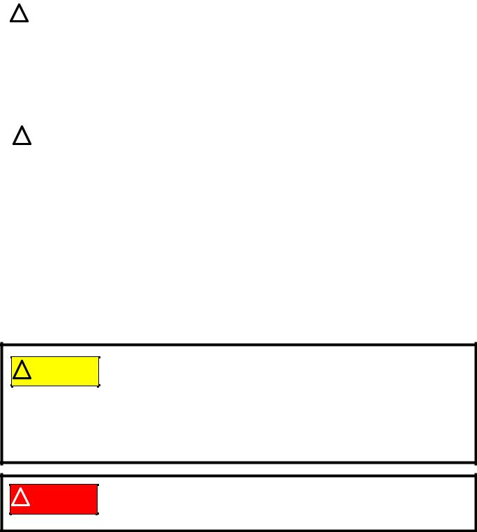
Caution is used to point out potential danger to the technician, operator, bystanders, or sur- |
|
|
|
! CAUTION |
|
||
|
|
|
rounding property. |
|
|
|
|
|
|
|
|
|
|
|
|
|
|
|
|
|
|
|
|
|
|
|
|
|
|
|
|
|
|
Warning indicates a potentially hazardous situation that, if not avoided, could result in death |
|
|
|
! WARNING |
|
||
|
|
|
or serious injury. |
|
|
|
|
|
|
|
|
|
|
|
|
|
|
|
|
|
|
|
|
|
|
|
|
|
|
|
|
|
|
Danger indicates an imminently hazardous situation that, if not avoided, will result in death or |
|
|
|
! DANGER |
|
||
|
|
|
serious injury. This signal word is to be limited to the most extreme situations |
|
|
|
|
|
|
|
|
|
|
|
|
|
|
1.Numbered steps indicate specific things that should be done, and the order in which they should be done.
1a. Substeps will be lettered and nested within steps. Two or more substeps may be combined to describe the actions required to complete a step.
Disclaimer: This manual is intended for use by trained, professional technicians.
•Common sense in operation and safety is assumed.
•In no event shall MTD be liable for poor text interpretation or poor execution of the procedures described in the text.
•If the person using this manual is uncomfortable with any procedures they encounter, they should seek the help of a qualified technician or MTD Technical Support.
Safety
This Service Manual is meant to be used along with the Operator’s Manual. Read the Operator’s Manual and familiarize yourself with the safety and operational instructions for the equipment being worked on. Keep a copy of the Operator’s Manual for quick reference. Operator’s manuals may be viewed for free at the brand support website. It will be necessary to have the complete model and serial number for the equipment.
1
P90 Series Vertical Shaft Engines
|
|
|
• |
Be prepared in case of emergency: |
|
|
! CAUTION |
|
|||
|
|
|
Keep a fire extinguisher nearby |
|
|
|
|
|
|
Keep a first aid kit nearby |
|
|
|
|
|
Keep emergency contact numbers handy |
|
|
|
|
• |
Replace any missing or damaged safety labels on shop equipment. |
|
|
|
|
• |
Replace any missing or damaged safety labels on equipment being serviced. |
|
|
|
|
|
|
|
|
|
|
|
|
|
|
|
|
• |
Grooming and attire: |
|
|
! WARNING |
|
|
Do not wear loose fitting clothing that may become entangled in equipment. |
|
|
|
|
|
Long hair should be secured to prevent entanglement in equipment. |
|
|
|
|
|
||
|
|
|
|
Jewelry is best removed. |
|
|
|
|
• |
Protective gear: includes, but is not limited to |
|
|
|
|
|
Clear eye protection ................................ |
while working around any machinery |
|
|
|
|
Protective gloves ..................................... |
where necessary |
|
|
|
|
Armored footwear .................................... |
when working around any machinery |
|
|
|
|
Hearing protection ................................... |
in noisy environments |
|
|
|
|
Chemically resistant gloves ..................... |
when working with chemicals or solvents |
|
|
|
|
Respirator ................................................ |
when working with chemical or solvents |
|
|
|
|
Appropriate tinted eye protection............. |
when cutting or welding |
|
|
|
|
Flame resistant headgear, jacket, chaps . when cutting or welding |
|
|
|
|
|
|
|
•Remember that some hazards have a cumulative effect. A single exposure may
! CAUTION |
cause little or no harm, but continual or repeated exposure may cause very serious |
harm. |
•Clean spills and fix obviously dangerous conditions as soon as they are noticed.
•Lift and support heavy objects safely and securely.
•Be aware of your surroundings and potential hazards that are inherent to all power equipment. All the labels in the world cannot protect a technician from an instant of carelessness.
! DANGER
•Exhaust fumes from running engines contain carbon monoxide (CO). Carbon monoxide is a colorless odorless gas that is fatal if inhaled in sufficient quantity. Only run engines in well ventilated areas. If running engines indoors, use an exhaust evacuation system with adequate make-up air ventilated into the shop.
2
Introduction
Fasteners
•Most of the fasteners used on the MTD engine are metric. Some are fractional inches. For this reason, wrench sizes are frequently identified in the text, and measurements are given in U.S. and metric scales.
•If a fastener has a locking feature that has worn, replace the fastener or apply a small amount of releasable thread locking compound such as Loctite® 242 (blue).
•Some fasteners, like cotter pins, are single-use items that are not to be reused. Other fasteners such as lock washers, retaining rings, and internal cotter pins (hairpin clips) may be reused if they do not show signs of wear or damage. This manual leaves that decision to the judgement of the technician.
Assembly instructions
•Torque specifications may be noted in the part of the text that covers assembly. They may be summarized in tables along with special instructions regarding locking or lubrication. Whichever method is more appropriate will be used. In many cases, both will be used so that the manual is handy as a quick-refer- ence guide as well as a step-by-step procedure guide that does not require the user to hunt for information.
•Lubricant quantity and specification may be noted in the part of the text that covers maintenance, and again in the section that covers assembly. They may also be summarized in tables along with special instructions. Whichever method is more appropriate will be used. In many cases, the information will be found in several places in the manual so that the manual is handy as a quick-reference guide as well as a step-by-step procedure guide that does not require the user to hunt for information.
•The level of assembly instructions provided will be determined by the complexity of reassembly, and by the potential for damage or unsafe conditions to arise from mistakes made in assembly.
•Some instructions may refer to other parts of the manual for subsidiary procedures. This avoids repeating the same procedure two or three times in the manual.
3
P90 Series Vertical Shaft Engines
MTD Vertical Engine Model Designators
• |
Starter/Alternator |
1 P 6 1 M U A |
|
s 1=Recoil start |
|
• |
2=Electric start (12V) |
Major Revision |
•3=E. start/alt. 18W
• 4=E. start/alt. 3A/5A |
Change |
•5= AutoChoke/ Recoil
• |
6= AutoChoke/Electric |
Compliance |
|
|
Start |
U |
United States (50 State) |
• |
7= AutoChoke/Electric |
||
|
Start/Alt |
H |
Europe |
|
|
C |
California |
|
P= Vertical (1 cyl.) |
0 (Zero) 49 State |
|
|
Q= Vertical (2 cyl.) |
G |
U.S.(49) and Europe |
|
W |
U.S.(50) and Europe |
|
|
|
||
|
Bore Dia. (mm) |
|
|
B |
Mower (long shaft M0) |
End Product |
|
|
|
||
C |
Chipper/Shredder |
M |
Mower (long shaft/no shroud) |
D |
Mower (long shaft M1) |
N |
Mower (short shaft M0) |
E |
Mower (short shaft M1) |
P |
Mower (long shaft M0) |
F |
Mower (short shaft/no shroud) |
Q |
Mower (short shaft M0) |
R |
Mower (long shaft/no shroud) |
T |
Tiller |
L |
Log splitter |
W |
World Tiller |
MTD Engine Serial Numbers
1P65FH/0510271A0023
Model number |
|
Year |
|
Month |
|
Date |
|
|
|
|
|
|
|
|
|
|
|
|
|
|
|
|
|
|
|
|
|
|
|
|
|
|
|
|
|
|
|
Producing Line# and Shift#: |
|
Engine |
|||
|
|
|
|
|
1A=Line 1, 1st Shift |
|
number |
|||
|
|
|
|
|
1B=Line 1, 2nd Shift |
|
|
|||
|
|
|
|
|
|
|
||||
|
|
|
|
|
2A=Line 2, 1st Shift |
|
|
|||
|
|
|
|
|
2B=Line 2, 2nd Shift |
|
|
|||
|
|
|
|
|
3A=Line 3, 1st Shift |
|
|
|||
|
|
|
|
|
3B=Line 3, 2nd Shift |
|
|
|||
|
|
|
|
|
4A=Line 4, 1st Shift |
|
|
|||
|
|
|
|
|
4B=Line 4, 2nd Shift |
|
|
|||
4
Introduction
Model and serial number
The model and serial number can be found on a white sticker with a bar code. The sticker is located between the dipstick and the muffler. See Figure 1.1.
Model /serial number
Oil screen
Muffler
 Dipstick
Figure 1.1
NOTE: The serial number will always start with the model number.
Maintenance
The recommended maintenance intervals listed in this manual are a guideline. They are adjustable for local conditions.
Maintenance items |
Interval |
|
|
|
|
Oil Change* |
50 hrs |
|
|
Oil filter |
200 hours |
|
|
Oil pre-screen |
Annually |
|
|
Clean the air filter |
100 hrs |
|
|
Replace the air filter |
200 hrs |
|
|
Spark plugs |
100 hrs |
|
|
Fuel filter |
100 hrs |
|
|
Clean the engine |
100 hours |
|
|
* First oil change at 5 hours.
5
P90 Series Vertical Shaft Engines
Spark plugs
The information in this manual applies to the MTD engine. Some basic principles may apply to engines produced by other manufacturers.
As the saying goes “an ounce of prevention is worth a pound of cure”. The same can be said about preventive maintenance on outdoor power equipment. By changing the spark plug and oil at recommended intervals many failures can be avoided.
NOTE: Please refer to Chapter 7: Ignition for the complete service instructions on spark plugs.
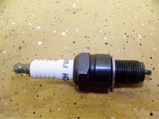
1.The spark plug used in the MTD engine is a F6RTC (part # 951-10292) gapped to 0.024” - 0.031” (0.60 - 0.80 mm). See Figure 1.2.
2. Wear rate will vary somewhat with severity of use. If the edges of the center electrode are rounded-off,
or any other apparent wear / damage occurs, replace the spark plug before operating failure (no start) occurs.
3.Cleaning the spark plug:
NOTE: MTD does not recommend cleaning spark plugs. Use of a wire brush may leave metal deposits on the insulator that causes the spark plug to short out and fail to spark. Use of abrasive blast for cleaning may cause damage to ceramic insulator or leave blast media in the recesses of the spark plug. When the media comes loose during engine operation, severe and non-warrantable engine damage may result.
4.Inspection of the spark plug can provide indications of the operating condition of the engine.
•Light tan colored deposits on insulator and electrodes is normal.
•Dry, black deposits on the insulator and electrodes indicate an over-rich fuel / air mixture (too much fuel or not enough air)
•Wet, black deposits on the insulator and electrodes indicate the presence of oil in the combustion chamber.
•Heat damaged (melted electrodes / cracked insulator / metal transfer deposits) may indicate detonation.
•A spark plug that is wet with fuel indicates that fuel is present in the combustion chamber, but it is not being ignited.
6
Introduction
Air filter
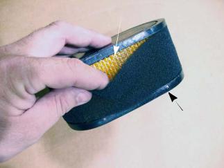
Paper-pleated element
Foam pre-filter
Figure 1.3
Generally air filters come in two different types, a pleated-paper element or foam. A combination of the two are used on the MTD engine. See Figure 1.3.
1.The main function of the air filter is to trap air borne particles before they enter the engine. Dirt ingestion can cause serious internal engine damage.
2.Air filters used on the MTD engine are designed to prevent particles larger than 3-5 micron from passing through into the engine.
3.The filter should be checked on a regular basis possibly several times in a season.
4.Typically an air filter should be changed before every season.
5.If a foam air pre-cleaner is dirty, but not in bad of condition, it can be cleaned and reused. The paper pleated filters can be shaken or lightly tapped to free the debris from the filter.
NOTE: Never use compressed air on a paper air filter. Compressed air will remove the tiny fibers that are used to catch the dirt in the air. Without these fibers the filter is useless.
6.Foam pre-filters can be washed in warm soapy water.
NOTE: When drying a foam filter either squeeze it inside of a paper towel or let it air dry. DO NOT wring it because the filter will tear.
7.Before installing any foam filter, after it has been washed, it needs to be free of moisture.
NOTE: Always check with factory specification prior to servicing/replacing any engine components. NOTE: Do not oil the foam pre-filter. The paper filer will absorb the oil and it will become plugged.
7
P90 Series Vertical Shaft Engines
Oil type and capacity
The recommended oil for MTD engines is an SAE 10W-30 oil with an SM API rating or better. The oil capacity for all of the P90 series engines is 57 fl.oz (1.7 liters).
•Check the oil level daily and change the oil more frequently in severe operating conditions such as high ambient temperature, dusty conditions, or high load use in exceptionally thick grass.
•Synthetic oil is a suitable alternative, but it does not extend service intervals.
NOTE: MTD recommends the use of petroleum oil during the break in period to ensure the piston rings correctly break in.
•Synthetic vs. Petroleum based oil: To simply look at synthetic oil and to compare it with Petroleum based oil there is very little difference. However, when you look at the two through a microscope it is easy to see the difference. Synthetic is made up of smaller molecules. This allows the oil to get into areas that petroleum based oil cannot.
•No oil additives or viscosity modifiers are recommended. The performance of a good oil meeting the API specifications will not be improved by oil additives.
NOTE: Some oil additives may cause severe and non warrantable engine damage, constituting a lubrication failure.
NOTE: If the oil is noticeably thin, or smells of gasoline, a carburetor repair may be needed before the engine can be run safely.
To check the oil:
1.Twist and remove the dipstick from the engine.
2.Clean the oil off of the tip of the dipstick.
3.Re-insert the dipstick and turn it until it is fully seated to get the oil level reading. See Figure 1.4.
4.The oil level is determined by the highest point on
the dipstick that is completely covered with oil.
Fully seat the dip stick before reading it
Figure 1.4
8

Changing the oil
Oil drain
Figure 1.5

 1/2” hose
Figure 1.6
Introduction
The oil change interval is every 100 hrs.
NOTE: The first oil change should be preformed at 8 hours.
NOTE: The oil filter should be replaced when the oil is changed.
To change the oil:
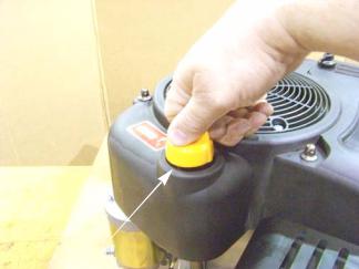
1.Remove the cap from the oil drain. See Figure 1.5.
2.Remove the dipstick.
3.Slide a piece of 1/2” hose onto the drain. See Figure 1.6.
4.Route the other end of the hose into an approved oil drain pan.
5.Turn the oil drain a quarter turn counter-clockwise to unlock it, then pull out 3/8” (9.5 mm) to open the valve.
6.After all of the oil has been drained, close the oil drain by pushing it in and turning it back a quarter turn.
7.Remove the drain hose.
8.Place the cap back on the oil drain.
9.Fill engine with 57 oz (1.7 L) of SAE 10W-30 oil with a SM API rating or better.
NOTE: Refer to the oil chart to determine the proper weight of oil to use.
10.Check the dip stick to verify that the oil is at the proper level before returning to service.
) |
) |
) |
) |
) |
) |
) |
|
|
|
|
|
6$( |
|
|
|
|
6$( |
|
|
|
|
6$( : 6$( : |
|
|
|||
6$( : |
|
|
|
|
|
|
& |
& |
& |
& |
& |
& |
& |
|
|
|
2LO &KDUW |
|
|
|
9
P90 Series Vertical Shaft Engines
Oil filter
To replace the oil filter:
1.Drain the oil by following the steps described in the previous section of this chapter.
2.Clean the area around the oil filter
3.Remove the oil filter by turning it counter-clockwise, as seen from the left side of the engine.
See Figure 1.7.
4.Place a light coating of oil on the O-ring of the new filter.
5.Pre-fill the new filter with fresh, clean oil.
6.Thread the new filter on to the engine. Hand tighten only.
7.Fill engine with 57 oz (1.7 L) of SAE 10W-30 oil with a SM API rating or better.
8.Test run the engine and check for leaks before returning the engine to service.
Oil filter
Figure 1.7
Oil pre-screen
To clean the pre-screen:
1.Drain the oil by following the procedures described in the previous section of this chapter.
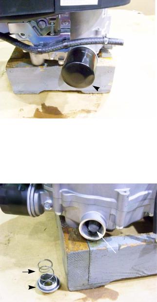
2.Remove the pre-screen plug using a 15/16” wrench.
NOTE: There is a spring that will come out with the plug. See Figure 1.8.
3.Remove the screen.
4. |
Inspect the o-ring for signs of damage or wear. |
Pre-screen |
|
Replace the o-ring if any are found. |
Spring |
|
5.Clean the screen in parts cleaning solution.
6. |
Rinse the screen in warm water. |
Plug |
|
|
|
||||
|
|
|
||
7. |
Dry the screen using compressed air. |
|
|
Figure 1.8 |
|
|
|
|
8.Install the screen.
9.Install the plug and spring.
10.Fill engine with 57 oz (1.7 L) of SAE 10W-30 oil with a SM API rating or better.
11.Test run the engine and check for leaks before returning the engine to service.
10
Introduction
Fuel system
What you should know about fuel.
Most of the fuel presently available in North America is oxygenated to some extent. This is commonly done through the addition of ethanol. Most engines offered for sale on outdoor power equipment in the North American markets are designed to tolerate no more than 10% ethanol by volume
Ethanol is hygroscopic, meaning it absorbs water. If left exposed to air, it will draw water out of the air.
Ethanol is an oxygenator, which means that it will oxidize (corrode) metal that it comes into contact with. Exposure to air causes fuel to go bad quickly, leaving gum and varnish deposits.
Fuel used in Cub Cadet outdoor power equipment should be no more than 30 days old. Because it may already have been stored at the refinery or gas station for a week or more, fuel should be purchased in small quantities and stored in safety approved gas cans with the caps closed.
For storage, all fuel should be run out of the tank and engine. Anti-oxidation additives will help keep the fuel fresher.
Servicing the fuel system
Inspect the fuel system every time the engine is operated. If dirty fuel is found in the fuel tank or fuel that does not smell “right”, drain the fuel tank and replace the fuel filter. Dispose of bad fuel in a safe and legal manner.
Refer to the units service manual for the procedures to drain the fuel tank.
|
|
|
|
|
|
|
|
Gasoline and its vapors are extremely flammable. Use common sense when working around |
|
|
|
! CAUTION |
||
|
|
the fuel system. Avoid sparks, open flames or heat sources that can ignite the fuel vapors. |
|
|
|
|
|
|
|
|
|
|
|
|
Fuel filter
 Fuel filter
Figure 1.9
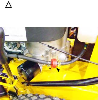
A dirty fuel filter can result in a lean run condition. The fuel filter should be replaced every 100 hours.
To replace the fuel filter:
NOTE: The part number for the fuel filter is BS - 298090S. It is a 150 micron (red) filter. Use of a filter with a lower micron rating will cause fuel starvation issues.
1.Clamp off the fuel lines to prevent fuel from leaking when the lines are disconnected. See Figure 1.9.
NOTE: Take care that the fuel lines are not damaged when clamping them off. Never insert a screw or anything else into the fuel line to prevent fuel from coming out. This will damage the inside of the fuel line.
NOTE: There are commercially available fuel line clamping tools that will not damage the fuel lines.
2.Squeeze the tabs on the fuel line clamps and slide them away from the filter.
3.Carefully slide the fuel lines off of the filter. If there are pieces of rubber on the barbs of the fuel filter, replace the affected fuel line.
IMPORTANT: The P90 series engines uses low permeation fuel line to meet EPA guidelines. When replacing the fuel lines, they must be replaced with the same type of low permeation fuel line.
4.Install the new filter by following the above steps in reverse order.
5.Test run the engine and check for leaks before returning to service.
11
P90 Series Vertical Shaft Engines
Valve lash
Valve lash is the clearance between the top of the valve stem and the rocker arm. The valve lash should be checked after the first 25 hours of use and every 100 hours after that. Valve lash can be checked and adjusted using the following steps:.
1.If the engine has been run, allow it to cool thoroughly. Position the mower for easy access to the cylinder head.
2.Disconnect the high-tension lead from the spark plug and ground it well away from the spark plug hole.
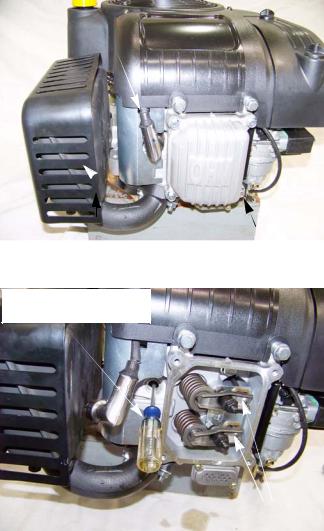
3.Remove the spark plug using a 13/16” or 21mm wrench. A flexible coupling or “wobbly” extension may help. See Figure 1.10.
High tension lead
Muffler |
Valve cover |
|
Figure 1.10
4.Remove the four bolts that secure the valve cover using a 10mm wrench, and remove the valve cover from the engine.
NOTE: If care is used not to damage the valve cover gasket, it can be re-used.
5.Confirm that the piston is at Top-Dead-Center on the compression stroke. See Figure 1.11.
•The compression stroke can be distinguished from the overlap stroke by the presence of air pressure at the spark plug hole and the fact that neither of the valves should move significantly on the compression stroke.
•There is an automatic compression release mechanism that “bumps” the exhaust valve as the piston rises on the compression stroke. At TDC, the exhaust valve should be fully closed.
Probe to confirm piston is at top of travel
Valves closed (push rods slack)
Figure 1.11
12
Introduction
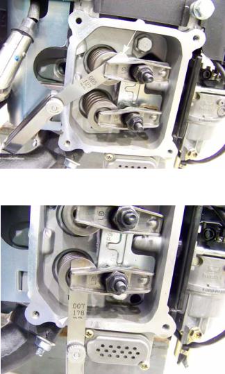
.005” feeler gauge
6. Check valve lash between each valve stem and rocker arm using a feeler gauge.
7. Intake valve lash (top valve) should be 0.004” - 0.006” (0.10 - 0.15mm). See Figure 1.12.
Figure 1.12
.007” feeler gauge
gauge
Figure 1.13
8.Exhaust valve lash (bottom valve) should be 0.006” - 0.008” (0.15 - 0.20mm). See Figure 1.13.
9.Use a 10mm wrench to loosen the jam nut, and a 14mm wrench to adjust the rocker arm fulcrum nut. See Figure 1.13.
•Tighten the rocker arm fulcrum nut to close-up the clearance between the end of the valve stem and the contact point on the rocker arm.
•Loosen the rocker arm fulcrum nut to open-up the clearance between the end of the valve stem and the contact point on the rocker arm.
10.Hold the fulcrum nut with a 14mm wrench, tighten the jam nut to a torque of 80 - 106 in-lb. (9 - 12 Nm) using a 10mm wrench.
11.Double-check the clearance after tightening the jam nut, to confirm that it did not shift. Re-adjust if necessary.
12.Rotate the engine through several compression cycles:
•Observe the movement of the valve gear.
•Return the piston to TDC compression stroke and re-check the valve lash to confirm consistent movement of the valve gear, including the slight bump to the exhaust valve from the automatic compression release.
13.Clean-up any oil around the valve cover opening, clean the valve cover, replace the valve cover gasket if necessary.
14.Install the valve cover, tightening the valve cover screws to a torque of 62 - 80 in-lbs (7 - 9 Nm). IMPORTANT: Over tightening the valve cover will cause it to leak.
15.Install the spark plug.
16.Test run the engine before returning it to service.
13

P90 Series Vertical Shaft Engines
Exhaust system
The exhaust system is a frequently overlooked component of an engine. It is important to make sure the muffler is in good condition and free of blockage.
NOTE: A blocked muffler will result in poor performance. If a muffler is completely blocked, the engine may not start.
Cleaning the engine
1.To maintain a proper operating temperature and to keep the equipment looking good, all debris should be removed from the engine.
2.It is recommended to use compressed air to blow all of the debris off of the engine.
NOTE: A pressure washer may be used to clean outdoor power equipment but only after the unit has been allowed to properly cool.
General torque specifications
|
|
|
VL]H |
0 |
0 |
0 |
0 |
VL]H |
0 |
0 |
0 |
|
|
|
|
|
|
||||||||||
|
|
|
VL]H |
0 |
0 |
0 |
0 |
VL]H |
0 |
0 |
0 |
|
|
|
|
|
VL]H |
0 |
0 |
0 |
0 |
VL]H |
0 |
0 |
0 |
|
|
|
*UDGH |
LQ OEV |
|
|
|
|
|
IW OEV |
|
|
|
|
|
|
|
|
|||||||||||
|
*UDGH |
LQ OEV |
|
|
|
|
|
IW OEV |
|
|
|
|
|
|
*UDGH |
LQ OEV |
|
|
|
|
|
IW OEV |
|
|
|
|
|
|
|
|
1P |
|
|
|
|
|
1P |
|
|
|
|
|
|
|
1P |
|
|
|
|
|
1P |
|
|
|
|
|
|
|
1P |
|
|
|
|
|
1P |
|
|
|
|
|
|
|
LQ OEV |
|
|
|
|
|
IW OEV |
|
|
|
|
|
|
|
LQ OEV |
|
|
|
|
|
IW OEV |
|
|
|
|
|
|
|
LQ OEV |
|
|
|
|
|
IW OEV |
|
|
|
|
|
|
|
1P |
|
|
|
|
|
1P |
|
|
|
|
|
|
|
1P |
|
|
|
|
|
1P |
|
|
|
|
|
|
|
1P |
|
|
|
|
|
1P |
|
|
|
|
|
|
|
LQ OEV |
|
|
|
|
|
IW OEV |
|
|
|
|
|
|
|
LQ OEV |
|
|
|
|
|
IW OEV |
|
|
|
|
|
|
|
LQ OEV |
|
|
|
|
|
IW OEV |
|
|
|
|
|
|
|
1P |
|
|
|
|
|
1P |
|
|
|
|
|
|
|
1P |
|
|
|
|
|
1P |
|
|
|
|
|
|
|
1P |
|
|
|
|
|
1P |
|
|
|
|
|
|
|
LQ OEV |
|
|
|
|
|
IW OEV |
|
|
|
|
|
|
|
LQ OEV |
|
|
|
|
|
IW OEV |
|
|
|
|
|
|
|
LQ OEV |
|
|
|
|
|
IW OEV |
|
|
|
|
|
|
|
1P |
|
|
|
|
|
1P |
|
|
|
|
|
|
|
1P |
|
|
|
|
|
1P |
|
|
|
|
|
|
|
1P |
|
|
|
|
|
1P |
|
|
|
|
|
|
|
LQ OEV |
|
|
|
|
|
IW OEV |
|
|
|
|
|
|
|
LQ OEV |
|
|
|
|
|
IW OEV |
|
|
|
|
|
|
|
LQ OEV |
|
|
|
|
|
IW OEV |
|
|
|
|
|
|
|
1P |
|
|
|
|
|
1P |
|
|
|
|
|
|
|
1P |
|
|
|
|
|
1P |
|
|
|
|
|
1RQFULWLFDO |
1P |
|
|
|
|
|
1P |
|
|
|
|
|
|
1RQFULWLFDO |
LQ OEV |
|
|
|
|
|
IW OEV |
|
|
|
|
|
|
1RQFULWLFDO |
|
|
||||||||||
|
)DVWHQHUVLQ |
LQ OEV |
|
|
|
|
|
IW OEV |
|
|
|
|
|
|
)DVWHQHUV LQ |
LQ OEV |
|
|
|
|
|
IW OEV |
|
|
|
|
|
|
)DVWHQHUV LQ |
1P |
|
|
|
|
|
1P |
|
|
|
|
|
|
$ |
OXPLQXP |
|
|
|||||||||
|
$ |
OXPLQXP |
1P |
|
|
|
|
|
1P |
|
|
|
|
|
$ |
OXPLQXP |
1P |
|
|
|
|
|
1P |
|
|
|
|
|
|
|
|
|
|
|
|
|
|
|
|
|
|
Useful Engine Specifications
Description |
SAE |
Metric |
|
|
|
|
|
|
Engine displacement |
25.6 cubic inch |
420 cc |
|
|
|
Spark plug gap |
0.024” - 0.031” |
0.6 - 0.8 mm |
|
|
|
Spark plug torque |
177 - 221 in lbs |
20 - 25 Nm |
|
|
|
Ignition module air gap |
0.016” - 0.024” |
0.4 - 0.6 mm |
|
|
|
Intake valve lash |
0.004” - 0.006” |
0.10 - 0.15 mm |
|
|
|
Exhaust valve lash |
0.006” - 0.008” |
0.15 - 0.20 mm |
|
|
|
Oil capacity |
57 oz |
1.7 L |
|
|
|
14
BASIC TROUBLESHOOTING
CHAPTER 2: BASIC TROUBLESHOOTING
Definitions
Troubleshooting - The act of gathering information by preforming tests and direct observations.
Diagnosis - Developing and testing theories of what the problem is, based on the information gathered in troubleshooting.
Introduction
Diagnosing an engine is an art form that is built upon several factors. First and most importantly is a good understanding of how the engine works. The second is skills that have been honed by experience. Finally the use of visual observations and a structured, systematic approach to troubleshooting a problem.
The first part of this chapter will outline the steps of troubleshooting an engine so a technician can form a proper diagnosis. The second half of this chapter will describe specific procedures and tests to perform while troubleshooting.
The first two rules in troubleshooting is to cause no further harm to the engine and prevent
! CAUTION injuries. Always make sure to check the oil for level and condition before starting an engine. Also check attachments for damage and make sure they are firmly mounted.
Steps to troubleshooting
NOTE: The steps and the order of the steps that follow are a suggested approach to troubleshooting the MTD engine. The technician does not necessarily have to follow them as described in this chapter.
Define the problem
The first step in troubleshooting is to define the problem:
•Crankshaft will not turn.
A.Starter not working
B.Engine in a bind (external - attachment jammed)
C.Engine in a bind (internal - engine seized)
•Crankshaft turns, no start
•Starts, runs poorly
A.Starts, then dies
B.Runs with low power output
C.Makes unusual smoke when running I. Black smoke, usually heavy
II.White smoke, usually heavy
III.Blue smoke. usually light
D. Makes unusual sounds when running
I.Knock
II. Click
III. Chirp
15
P90 Series Vertical Shaft Engines
IV. Unusual exhaust tone
There are tools that the technician can use in order to define the problem, such as:
1.Interview the customer.
1a. Get a good description of their complaint.
1b. If it is an intermittent problem, verify what conditions aggravate the problem as best as possible. 1c. Get an accurate service history of the equipment.
1d. Find out how the customer uses and stores the equipment.
2.Direct observation:
2a. Do not automatically accept that the customer is correct with their description of the problem. Try to duplicate the problem.
2b. Check the general condition of the equipment (visually).
I.Cleanliness of the equipment will indicate the level of care the equipment has received.
II. Make sure the engine and attachments are securely fastened. III. The tune-up factors.
NOTE: Most hard starting and poor running conditions can be solved by performing a tune-up.
a.Check the condition and amount of oil in the crankcase.
b.Check the level and condition of the fuel.
c.Check the ignition and “read” the spark plug.
d.Look for obvious signs of physical damage, exhaust system blockage or cooling system blockage.
16
BASIC TROUBLESHOOTING
Identify factors that could cause the problem
This is the second step in the troubleshooting process.
1.Crankshaft will not turn.
A. Starter not working. This can be an electrical failure or a mechanical failure. The likely suspects are: I. A dead battery.
II. A bad ground
III.A failure in the electrical circuit. IV. A failure of the starter itself.
B.Engine in a bind (external - attachment jammed). This usually indicates that the unit being powered by the engine either failed or has something jammed in it, locking up the system.
C.Engine in a bind (internal - engine seized). This is usually either a quick fix or a catastrophic failure. The likely suspects are:
I.Complete hydraulic lock (easy fix).
II. Bent crankshaft (unrepairable)
III.Internal binding, crankshaft, connecting rod or piston (unrepairable)
2.Crankshaft turns, no start.
2a. Most gasoline engine diagnosis involves isolating problems in the four critical factors an engine needs to run properly:
I.Ignition- sufficient spark to start combustion in the cylinder, occurring at the right time.
II.Compression- enough pressure in the cylinder to convert combustion into kinetic motion. It also needs sufficient sealing to generate the vacuum needed to draw in and atomize the next intake charge.
III.Fuel- correct type and grade of fresh gasoline; in sufficient quantity, atomized (tiny droplets) and in correct fuel/air proportions.
IV. Flow- if all of the above conditions are met but the flow of air is constricted on the inlet or exhaust side, it will cause the engine to run poorly or not at all. This also includes ensuring the valves are timed to open at the proper time.
2a. Isolate the ignition system and compression from the fuel system by preforming a prime test.
I.Burns prime and dies. This would indicate a fuel system issue.
II. Does not burn prime. Not a fuel system issue. Check for an ignition, compression or flow problem. 2c. Compression or ignition problem
I.Check the engine stop and safety switch.
II. Test the ignition system using a proper tester.
III. Replace the spark plug with a new one or a known good one.
IV. Check compression or leak down.
V. Check valve lash.
VI. Check valve timing/actuation.
VII. Check exhaust.
3.Starts, runs poorly 3a. Starts, then dies
17
P90 Series Vertical Shaft Engines
I.Run the engine with a spark tester in-line between the spark plug wire and the spark plug or use an oscilloscope and see if the spark goes away at the same time the engine dies.
II. Check choke operation.
a.Black smoke?
b.Wet plug?
III.Prime test immediately after engine dies. If it restarts, this may indicate a problem with fuel flow to the carburetor. Check the gas cap, fuel line, fuel filter, and the float in the carburetor.
3b. Runs with low power output.
I.Look for unusual exhaust color (smoke).
II. Unusually hot muffler (may glow red).
a.Retarded ignition
b.Exhaust valve opening early (lash too tight) III. Mechanical bind
a.A slightly bent crankshaft. In some cases the drag may increase and decrease as the crankshaft rotates. This produces a pulsing feeling that is different than a jerk back.
b.Parasitic external load. A bind in the equipment the engine is powering.
c.Internal drag from a scored piston or similar damage.
IV. Low governor setting or stuck governor.
a.Check RPMs using a tachometer.
b.RPMs should not droop under moderate to heavy loads. V. Low compression
a.Check valve lash
b.Check compression
c.Check leak down to identify the source of the compression loss. VI. Flow blockage
a.Exhaust blockage, usually accompanied by an unusual exhaust sound.
•Just as a throttle on the carburetor controls the engine RPMs by limiting the amount of air an engine can breathe in, an exhaust blockage will limit engine performance by constricting the other end of the system.
•The muffler itself my be blocked.
•The exhaust valve may not be opening fully, possibly because of extremely loose valve lash settings.
•The exhaust valve seat may have come loose in the cylinder head. This may cause a loss of compression, a flow blockage or it may randomly alternate between the two.
NOTE: The cause of an exhaust valve coming loose is usually over heating.
b.Intake blockage
•An intake blockage up-stream of the carburetor will cause a rich fuel/air mixture and constrict the amount of air that the engine can draw in, limiting performance.
•The intake valve not fully opening. A possible cause of this is loose valve lash.
18
BASIC TROUBLESHOOTING
V.Makes unusual smoke when running
a.Black smoke, usually heavy, usually indicates a rich air fuel mixture
•Not enough air: air flow blockage or a partially closed choke.
•Too much fuel: carburetor float or float valve stuck or metering / emulsion issues with the carburetor.
b.White smoke, usually heavy
•Oil in muffler, usually the result of improper tipping. The engine will “fog” for a minute or so, then clear-up on its own.
•Massive oil dilution with gasoline. It may be caused by improper tipping. It can also be caused by leaky carburetor float valve, if there is a down-hill path from the carburetor to the intake port. Check oil for gasoline smell, repair carburetor.
c.Blue smoke, usually light.
PCV system
•May be blocked or unplugged.
•May be over-come by massive over-filling or oil dilution with gasoline.
•Will cause oil to exit the engine via any low-resistance paths.
Piston rings
•Confirm with leak-down test.
•Smoke will be more pronounced under load.
•Repair may not make economic sense. Valve guides (and intake valve stem seal).
•Smoke will be more pronounced on over-run. VI. Makes unusual noise when running
a.Knock
•Check for loose mounting of engine or driven implement
•Rotate crankshaft back-and-forth to check for loose connecting rod.
b.Click
•Clicks and pops on engine shut-down: Compression release coming into play as the engine RPMs cross the activation threshold. This will have no ill effects on engine performance.
•Half-engine speed clatter: loose valve lash.
•Half-engine speed clatter, slightly heavier: wrist-pin.
•Rhythmic heavy-light engine speed click: piston slap
c.Spark-knock
•Advanced ignition timing
•Low octane fuel
•Over-heating engine (check for blocked cooling air flow)
•Carbon build-up in cylinder: glowing carbon chunks pre-igniting air fuel mix.
d.Chirp
•Compression, blowing-by the fire-ring of a damaged head gasket will sometimes produce a
19
P90 Series Vertical Shaft Engines
chirping noise.
•Confirm with a compression test and leak-down test. e. Unusual exhaust tone
Splashy or blatty
•Splashy idle usually indicates a slight rich condition.
•May indicate an exhaust blockage, usually slightly muffled. Backfire
•On over-run: unburned fuel igniting past exhaust valve. Mixture not burning completely in combustion chamber. It may be too rich or it may be spark-plug or ignition problem.
•Occasional, under load: engine momentarily runs lean, usually will cycle with float bowl level or governor pull-in, sometimes sounds like a slight stumble. Ethanol content exceeding 10% will make the engine run artificially lean.
Skip
•Usually ignition related.
•Run the engine with a spark tester in-line between the spark plug wire and the spark plug or use an oscilloscope and see if the spark goes away at the same time the engine dies.
4.Engine over-speed
A.Continual over-speed
•Binding or damaged external governor linkage or carburetor throttle.
•Mis-adjusted governor arm.
•Internal governor failure.
B.Momentary over-speed
•Intermittent bind (very unusual).
•Interference: This is fairly common when debris can fall on the governor linkage during normal operations.
5.Engine RPMs surge (hunting)
A.Over-governed conditionReturn spring replaced with wrong part or hooked into wrong hole.
NOTE: This is an extremely rare condition, usually created by tampering.
B.Lean Air-fuel mixture conditionWhen AFR (Air Fuel Ratio) is significantly below stoichiometric ratio (14.7:1) engine RPMs sink until they reach a point that can be supported by the available fuel. This causes a momentary surge in power until the available fuel is consumed, then the RPMs fall again, repeating the cycle.
•Too much air: look for an air leak in the intake tract
•Not enough fuel: look for fuel supply or carburetor problems
20
BASIC TROUBLESHOOTING
Repairing the problem
The third step in the troubleshooting process is to repair the problem. This step consists of:
A.Form a diagnosis by using all of the information gathered from the troubleshooting that was performed.
B.Physically perform the repair.
The fourth, and hopefully final, step in the troubleshooting process is the follow through. This step consists of:
A.Thoroughly test the repaired equipment: confirming that the initial diagnosis was correct. If it was wrong, start the troubleshooting process over again.
NOTE: Sometimes the engine will have multiple problems at the same time. By performing one repair, other issues may show up that are unrelated to the first repair.
B.Delivery to customer: We are not just repairing equipment, we are repairing customers.
•Inoculate against recurring problem with education, e.g.: if the problem was caused by stale fuel, make sure the customer is aware that fuel goes bad over time.
•Make sure the customer understands the repair, preventing “superstitious” come-backs.
21
P90 Series Vertical Shaft Engines
Prime test
To perform a prime test:
1.Prime the engine through the carburetor throat using a squirt bottle, filled with clean fresh gasoline.
2.Make sure the throttle is in the run position.
3.Attempt to start the engine.
4.If the engine starts and runs long enough to burn the prime, the problem is effectively isolated to the fuel system. Proceed to Chapter 4: The Fuel System and Governor.
5.If the engine did not start, check ignition system as described in Chapter 7: Ignition System.
6.If the ignition system is working, check the compression or perform a leak down test.
Leak-down test
A leak-down test is the preferred method to test the engine’s ability to compress the charge. It will also show where pressure is leaking from.
To perform a leak-down test:
NOTE: A leak down test pressurizes the combustion chamber with an external air source and will allow the technician to listen for air “leaking“ at the valves, piston rings and the head gasket.
NOTE: These are general instructions. Read and follow the instructions that came with the tester before attempting to perform this test.
•If possible, run the engine for 3-5 minutes to warm up the engine.
•Remove the spark plug and air filter.
•Find top dead center of the compression stroke.
|
|
If the engine is not centered at top dead center, the engine will rotate when compressed air is |
|
! CAUTION |
|
|
introduce to the combustion chamber. |
|
|
|
|
1.Find top dead center by following the steps described in the valve lash section of Chapter 1: Introduction
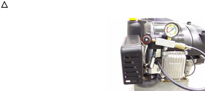
2.Thread the leak down tester adapter into the spark plug hole. See Figure 2.1.
3.Connect tester to compressed air.
4.Adjust the regulator knob until the needle on the gauge is in the yellow or set area of the gauge.
5.Connect the tester to the adapter.
NOTE: If the engine rotates it was not at top dead center.
6.Check the reading on the gauge.
Leak down tester
Leak-down tester adapter
Figure 2.1
22
BASIC TROUBLESHOOTING
7.Compare the results to the following chart.
Leak-down Testing Results
Symptom |
Possible cause |
|
|
|
|
Air escaping from |
Worn cylinder or piston rings. |
the breather |
Possible blown head gasket |
|
|
Air escaping from |
Leaking exhaust valve |
the exhaust |
|
|
|
Air escaping from |
Leaking intake valve |
the carburetor |
|
|
|
Gauge reading |
Cylinder and piston rings are in |
low |
good condition |
|
|
Gauge reading |
There is some wear in the |
moderate |
engine, but it is still usable |
|
|
Gauge reading |
excessive wear of cylinder and/ |
high |
or piston rings. Engine should |
|
be short blocked or it could be a |
|
blown head gasket. |
|
|
23
P90 Series Vertical Shaft Engines
Compression test
To perform a compression test:
NOTE: Compression should be in the range of 55 - 80 PSI (3.8 - 5.5 Bar).
•Disconnect the high-tension lead from the spark plug and ground it well away from the spark plug hole.
•Remove the spark plug using a 13/16” or 21mm wrench. A flexible coupling or “wobbly” extension may help.
•Pull the starter rope several times to purge any fuel or oil from the combustion chamber.
NOTE: Air compresses readily, liquid does not. Liquid in the combustion chamber will result in an artificially high compression reading.
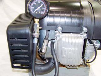
1.Install a compression gauge in the spark plug hole.
2.Confirm that the gauge is “zeroed”, then pull the starter rope repeatedly, until the needle on the gauge stops rising. See Figure 2.2.
3.Interpreting compression readings.
 Compression gauge
Figure 2.2
Compression Readings |
||
|
|
|
Readings in |
Possible causes |
|
psi |
||
|
||
|
|
|
|
|
|
<20 |
Most likely a stuck valve or |
|
(1.4 Bar) |
too tight of a valve lash, |
|
|
provided the starter rope |
|
|
pulls with normal effort. |
|
|
|
|
20 - 55 |
Valve seat damage or pis- |
|
(1.4-3.8 Bar) |
ton ring and/or cylinder |
|
|
wear. |
|
|
|
|
55 - 80 |
Normal readings |
|
(3.8-5.5 Bar) |
|
|
|
|
|
>80 |
Excessive valve lash, a |
|
(>5.5 Bar) |
partial hydraulic lock, a bad |
|
|
cam or a bad automatic |
|
|
compression relief. |
|
|
|
|
24
 Loading...