


CTs Multi-Channel Series
CTs 4200
Operation Manual
CTs 8200
Obtaining Other Language Versions: To obtain information in another language about the use of this product, please contact your local Crown Distributor. If you need assistance locating your local distributor, please contact Crown at 574-294-8000.
This manual does not include all of the details of design, production, or variations of the equipment. Nor does it cover every possible situation which may arise during installation, operation or maintenance.
The information provided in this manual was deemed accurate as of the publication date. However, updates to this information may have occurred. To obtain the latest version of this manual, please visit the Crown website at www.crownaudio.com.
Trademark Notice: Crown, Crown Audio, Amcron, Com-Tech, IQ System, and Multi-Mode are registered trademarks of Crown International. Other trademarks are the property of their respective owners.
Some models may be exported under the name Amcron.®
©2005 by Crown Audio® Inc., 1718 W. Mishawaka Rd., Elkhart, Indiana 46517-9439 U.S.A. Telephone: 574-294-8000
134434-7A 3/05
CTs Multi-Channel Power Amplifiers
Important Safety
Instructions
1)Read these instructions.
2)Keep these instructions.
3)Heed all warnings.
4)Follow all instructions.
5)Do not use this apparatus near water.
6)Clean only with a dry cloth.
7)Do not block any ventilation openings. Install in accordance with the manufacturer’s instructions.
8)Do not install near any heat sources such as radiators, heat registers, stoves, or other apparatus (including amplifiers) that produce heat.
9)Do not defeat the safety purpose of the polarized or grounding-type plug. A polarized plug has two blades with one wider than the other. A grounding-type plug has two blades and a third grounding prong. The wide blade or the third prong is provided for your safety. If the provided plug does not fit into your outlet, consult an electrician for replacement of the obsolete outlet.
10)Protect the power cord from being walked on or pinched, particularly at plugs, convenience receptacles, and the point where they exit from the apparatus.
11)Only use attachments/accessories specified
by the manufacturer.
12) Use only with a cart, stand, tripod, bracket, or table specified by the manufacturer, or sold with the apparatus. When a cart is used, use caution when moving the cart/apparatus combination to avoid injury from tip-over.
13)Unplug this apparatus during lightning storms or when unused for long periods of time.
14)Refer all servicing to qualified service personnel. Servicing is required when the apparatus has been damaged in any way, such as powersupply cord or plug is damaged, liquid has been spilled or objects have fallen into the
apparatus, the apparatus has been exposed to rain or moisture, does not operate normally, or has been dropped.
15)WARNING: TO REDUCE THE RISK OF FIRE OR ELECTRIC SHOCK, DO NOT EXPOSE THIS APPARATUS TO RAIN OR MOISTURE.
16)DO NOT EXPOSE TO DRIPPING OR SPLASHING. DO NOT PLACE OBJECTS FILLED WITH LIQUID, SUCH AS VASES,ON THIS APPARATUS.
TO PREVENT ELECTRIC SHOCK DO NOT REMOVE TOP OR BOTTOM COVERS. NO USER SERVICEABLE PARTS INSIDE. REFER SERVICING TO QUALIFIED SERVICE PERSONNEL.
À PRÉVENIR LE CHOC ÉLECTRIQUE N’ENLEVEZ PAS LES COUVERCLES. IL N’Y A PAS DES PARTIES SERVICEABLE À L’INTÉRIEUR. TOUS REPARATIONS DOIT ETRE FAIRE PAR PERSONNEL QUALIFIÉ SEULMENT.
TO COMPLETELY DISCONNECT THIS EQUIPMENT FROM THE AC MAINS, DISCONNECT THE POWER SUPPLY CORD PLUG FROM THE AC RECEPTACLE. THE MAINS PLUG OF THE POWER SUPPLY CORD SHALL REMAIN READILY OPERABLE.
IMPORTANT
CTs Series amplifiers require Class 2 output wiring.
MAGNETIC FIELD
CAUTION! Do not locate sensitive high-gain equipment such as preamplifiers or tape decks directly above or below the unit. Because this amplifier has a high power density, it has a strong magnetic field which can induce hum into unshielded devices that are located nearby. The field is strongest just above and below the unit.
If an equipment rack is used, we recommend locating the amplifier(s) in the bottom of the rack and the preamplifier or other sensitive equipment at the top.
WATCH FOR THESE SYMBOLS:
The lightning bolt triangle is used to alert the user to the risk of electric shock.
The exclamation point triangle is used to alert the user to important operating or maintenance instructions.
FCC COMPLIANCE NOTICE
This device complies with part 15 of the FCC rules. Operation is subject to the following two conditions: (1) This device may not cause harmful interference, and (2) this device must accept any interference received, including interference that may cause undesired operation.
CAUTION: Changes or modifications not expressly approved by the party responsible for compliance could void the user’s authority to operate the equipment.
NOTE: This equipment has been tested and found to comply with the limits for a Class B digital device, pursuant to part 15 of the FCC Rules. These limits are designed to provide reasonable protection against harmful interference in a residential installation. This equipment generates, uses, and can radiate radio frequency energy and, if not installed and used in accordance with the instruction manual, may cause harmful interference to radio communications. However, there is no guarantee that interference will not occur in a particular installation. If this equipment does cause harmful interference to radio or television reception, which can be determined by turning the equipment off and on, the user is encouraged to try to correct the interference by one or more of the following measures:
•Reorient or relocate the receiving antenna.
•Increase the separation between the equipment and receiver.
•Connect the equipment into an outlet on a circuit different from that to which the receiver is connected.
•Consult the dealer or an experienced radio/TV technician for help.
page 2 |
Operation Manual |

CTs Multi-Channel Power Amplifiers
Crown International, Inc.
DECLARATION of CONFORMITY
ISSUED BY: Crown International, Inc. |
FOR COMPLIANCE QUESTIONS ONLY: Sue Whitfield |
1718 W. Mishawaka Road |
574-294-8289 |
Elkhart, Indiana 46517 U.S.A. |
swhitfield@crownintl.com |
|
|
European Representative's Name and Address: |
|
Nick Owen |
|
35, Bassets Field |
|
Thornhill |
|
Cardiff. South Glamorgen |
|
CF14 9UG United Kingdom |
|
Equipment Type: Commercial Audio Power Amplifiers
Family Name: CTs
Model Names: CTs 4200A, CTs 8200A
EMC Standards:
EN 55103-1:1995 Electromagnetic Compatibility - Product Family Standard for Audio, Video, Audio-Visual and Entertainment Lighting Control Apparatus for Professional Use, Part 1: Emissions
EN 55103-1:1995 Magnetic Field Emissions-Annex A @ 10 cm and 1 M
EN 61000-3-2:1995+A14:2000 Limits for Harmonic Current Emissions (equipment input current ≤ 16A per phase)
EN 61000-3-3:1995 Limitation of Voltage Fluctuations and Flicker in Low-Voltage Supply Systems Rated Current ≤ 16A
EN 55022:1992 + A1: 1995 & A2:1997 Limits and Methods of Measurement of Radio Disturbance Characteristics of ITE: Radiated, Class B Limits; Conducted, Class B
EN 55103-2:1996 Electromagnetic Compatibility - Product Family Standard for Audio, Video, Audio-Visual and Entertainment Lighting Control Apparatus for Professional Use, Part 2: Immunity
EN 61000-4-2:1995 Electrostatic Discharge Immunity (Environment E2-Criteria B, 4k V Contact, 8k V Air Discharge)
EN 61000-4-3:1996 Radiated, Radio-Frequency, Electromagnetic Immunity (Environment E2, criteria A)
EN 61000-4-4:1995 Electrical Fast Transient/Burst Immunity (Criteria B)
EN 61000-4-5:1995 Surge Immunity (Criteria B)
EN 61000-4-6:1996 Immunity to Conducted Disturbances Induced by Radio-Frequency Fields (Criteria A)
EN 61000-4-11:1994 Voltage Dips, Short Interruptions and Voltage Variation
Safety Standard:
EN 60065: 1998 Safety Requirements - Audio Video and Similar Electronic Apparatus
I certify that the product identified above conforms to the requirements of the EMC Council Directive 89/336/EEC as amended by 92/31/EEC, and the Low Voltage Directive 73/23/EES as amended by 93/68/EEC.
Signed
Larry Coburn |
Date of Issue: March 1, 2002 |
Title: Senior Vice President of Manufacturing |
|
Operation Manual |
Due to line current harmonics, we recommend that you contact your supply authority before connection. |
page 3 |

CTs Multi-Channel Power Amplifiers
Important Safety Instructions ....................................................... |
2 |
5.1.4 35-Hz High-Pass Filter ........................................... |
14 |
|
Declaration of Conformity ............................................................ |
3 |
5.1.5 AC Under-/Over-Voltage Protection ....................... |
14 |
|
1 Welcome ..................................................... |
5 |
5.1.6 Power Fuse ............................................................. |
14 |
|
1.1 |
Features ........................................................................... |
5 |
5.1.7 Inrush Limiting ....................................................... |
14 |
2 How to Use This Manual .................................. |
5 |
5.1.8 Variable-speed Fans ............................................... |
14 |
|
3 Setup ......................................................... |
6 |
5.2 Advanced Features .......................................................... |
14 |
|
3.1 |
Unpack Your Amplifier ..................................................... |
6 |
5.2.1Switching Power Supply .......................................... |
14 |
3.2 |
Install Your Amplifier ....................................................... |
6 |
5.2.2 Mode Switch .......................................................... |
14 |
3.3 |
Ensure Proper Cooling .................................................... |
6 |
5.2.3 Bridge Mode Indicator ............................................ |
14 |
3.4 |
Choose Input Wire and Connectors ................................. |
7 |
5.2.4 Channel Level Control ............................................ |
15 |
3.5 |
Choose Output Wire and Connectors ............................... |
7 |
5.3 Options ............................................................................ |
16 |
3.6 |
Wire Your System ............................................................ |
8 |
5.3.1 Control Modules .................................................... |
16 |
|
3.6.1 Dual 8/4 Mode ........................................................ |
8 |
5.3.2 Input Sensitivity ...................................................... |
16 |
|
3.6.2 Dual 70V Mode ....................................................... |
8 |
6 Troubleshooting ............................................ |
17 |
|
3.6.3 Bridge-Mono 16/8 Mode ........................................ |
9 |
7 Specifications .............................................. |
19 |
|
3.6.4 Bridge-Mono 100V Mode ....................................... |
9 |
8 AC Power Draw and Thermal Dissipation .............. |
23 |
3.7 |
Connect to AC Mains ....................................................... |
10 |
9 Service ...................................................... |
25 |
3.8 |
Startup Procedure ............................................................ |
10 |
9.1. International and Canada Service ................................... |
25 |
4 Operation .................................................... |
11 |
9.2 US Service ....................................................................... |
25 |
|
4.1 |
Precautions ...................................................................... |
11 |
9.2.1 Service at a US Service Center ............................... |
25 |
4.2 Front Panel Controls and Indicators ................................. |
12 |
9.2.2 Factory Service ....................................................... |
25 |
|
4.3 |
Back Panel Controls and Connectors ............................... |
13 |
9.2.3 Factory Service Shipping Instructions ..................... |
25 |
5 Advanced Features and Options.......................... |
14 |
9.2.4 Packing Instructions................................................ |
25 |
|
5.1 |
Protection Systems .......................................................... |
14 |
9.2.5 Estimate Approval.................................................... |
25 |
|
5.1.1 Thermal Level Control (TLC) .................................. |
14 |
9.2.6 Payment of Non-Warranty Repairs........................... |
25 |
|
5.1.2 Fault ....................................................................... |
14 |
10 Warranty ................................................... |
26 |
|
5.1.3 Fault Isolation Topology (FIT) ................................. |
14 |
Crown Factory Service Information Form .................................... |
29 |
page 4 |
Operation Manual |
CTs Multi-Channel Power Amplifiers
CTs 4200
Dual |
Maximum Average Power |
||
in watts with 0.1% THD. |
|||
4 Channels Driven |
1 kHz |
20 |
Hz–20 kHz |
4-ohm (per ch.) |
260W |
|
215W |
8-ohm (per ch.) |
180W |
|
190W |
70V (per ch.) |
220W |
|
220W* |
1 Channel Driven |
1 kHz |
20 |
Hz–20 kHz |
4-ohm (per ch.) |
270W |
|
225W |
8-ohm (per ch.) |
220W |
|
210W |
70V (per ch.) |
250W |
|
245W* |
Bridge-Mono |
|
|
|
2 Channel-Pairs Driven |
1 kHz |
20 |
Hz–20 kHz |
8-ohm (per ch. pair) |
520W |
|
430W |
16-ohm (per ch. pair) |
400W |
|
380W |
100V (per ch. pair) |
220W |
|
220W* |
1 Channel-Pair Driven |
1 kHz |
20 |
Hz–20 kHz |
8-ohm (per ch. pair) |
560W |
|
450W |
16-ohm (per ch. pair) |
440W |
|
420W |
100V (per ch. pair) |
250W |
|
245W* |
* Constant Voltage full bandwidth power ratings support 100Hz - 20kHz due to automatic High-Pass Filters.
CTs 8200
Dual |
Maximum Average Power |
||
in watts with 0.1% THD. |
|||
8 Channels Driven |
1 kHz |
20 |
Hz–20 kHz |
4-ohm (per ch.) |
200W |
|
175W |
8-ohm (per ch.) |
160W |
|
155W |
70V (per ch.) |
200W |
|
185W* |
1 Channel Driven |
1 kHz |
20 |
Hz–20 kHz |
4-ohm (per ch.) |
270W |
|
230W |
8-ohm (per ch.) |
220W |
|
220W |
70V (per ch.) |
250W |
|
230W* |
Bridge-Mono |
|
|
|
4 Channel-Pairs Driven |
1 kHz |
20 |
Hz–20 kHz |
8-ohm (per ch. pair) |
400W |
|
350W |
16-ohm (per ch. pair) |
320W |
|
310W |
100V (per ch. pair) |
200W |
|
185W* |
1 Channel-Pair Driven |
1 kHz |
20 |
Hz–20 kHz |
8-ohm (per ch. pair) |
540W |
|
460W |
16-ohm (per ch. pair) |
440W |
|
440W |
100V (per ch. pair) |
250W |
|
230W* |
* Constant Voltage full bandwidth power ratings support 100Hz - 20kHz due to automatic High-Pass Filters.
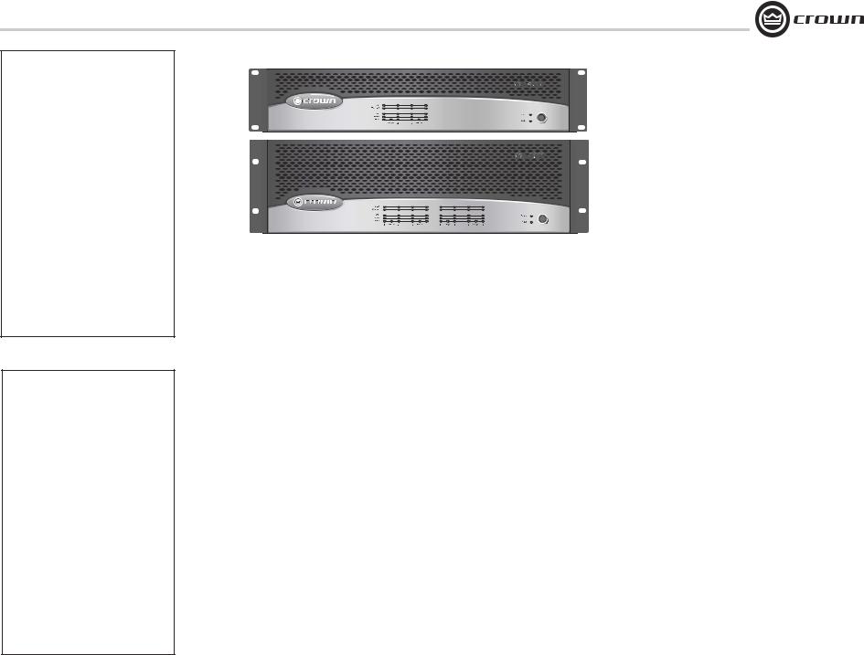
1 Welcome
Building on the foundation of the Com-Tech® Series, Crown’s CTs Series offers new flexibility and value for installed sound applications. The Com-Tech Series were the first to offer independent selection of highand low-impedance operation for a specific channel, and CTs Series amplifiers continue that tradition, with power levels and features carefully chosen to perfectly integrate into fixed install design requirements.
Modern power amplifiers are sophisticated pieces of engineering capable of producing extremely high power levels. They must be treated with respect and correctly installed if they are to provide the many years of reliable service for which they were designed.
In addition, CTs Series amplifiers include a number of features which require some explanation before they can be used to their maximum advantage.
Please take the time to study this manual so that you can obtain the best possible service from your amplifier.
1.1 Features
•New Crown® Switching Power Supply for reduced weight.
•High power-density, with eight channels in a 3U chassis and four channels in a 2U chassis.
•Selectable constant-voltage (70V/100V) or low-impedance (8/4 ohm) operation for each channel pair.
•FIT (Fault Isolation Topology) circuitry isolates faults within affected channels.
•35 Hz High-Pass Filter (70 Hz in CTs 4200) is automatically inserted when the channel pair is set for constant-voltage operation. (corner frequency may be changed as a service option).
•Accepts new MC accessory modules that tailor the amplifier to suit specific applica-
tions. Modules available for remote VCA level control and IQ System® Control.
•Comprehensive array of indicators including Power and Data, along with Bridge, Ready, Signal, Clip, Thermal and Fault for each channel, provide accurate diagnostics.
•Blue Power Indicator flashes if the amplifier shuts off due to an under-/over-voltage condition on the AC mains.
•Advanced protection circuitry guards against: shorted outputs, open circuits, DC, mismatched loads, general overheating, under-/over-voltage, high-frequency overloads and internal faults.
•Proven Crown AB+B Multi-Mode® output topology.
•Continuously-variable-speed fans optimize cooling efficiency.
•Three Year, No-Fault, Fully-Transferable Warranty completely protects your investment and guarantees its specifications.
2 How to Use This Manual
This manual provides you with the necessary information to safely and correctly setup and operate your amplifier. It does not cover every aspect of installation, setup or operation that might occur under every condition. For additional information, please consult Crown’s
Amplifier Application Guide (available online at www.crownaudio.com), Crown Tech Support, your system installer or retailer.
We strongly recommend you read all instructions, warnings and cautions contained in this manual. Also, for your protection, please send in your warranty registration card today, or register online at www.crownaudio.com. And save your bill of sale—it’s your official proof of purchase.
Operation Manual |
page 5 |
CTs Multi-Channel Power Amplifiers
3 Setup
3.1 Unpack Your Amplifier |
3.2 Install Your Amplifier |
Please unpack and inspect your amplifier for any damage that may have occurred during transit. If damage is found, notify the transportation company immediately. Only you can initiate a claim for shipping damage. Crown will be happy to help as needed. Save the shipping carton as evidence of damage for the shipper’s inspection.
We also recommend that you save all packing materials so you will have them if you ever need to transport the unit. Never ship the unit without the factory pack.
YOU WILL NEED (not supplied):
•Input wiring cables
•Output wiring cables
Rack for mounting amplifier (or a stable surface for stacking)
WARNING: Before you start to set up your amplifier, make sure you read and observe the Important Safety Instructions found at the beginning of this manual.
CAUTION: Before you begin, make sure your amplifier is disconnected from the power source, with the power switch in the “off” position and all level controls turned completely down (counterclockwise).
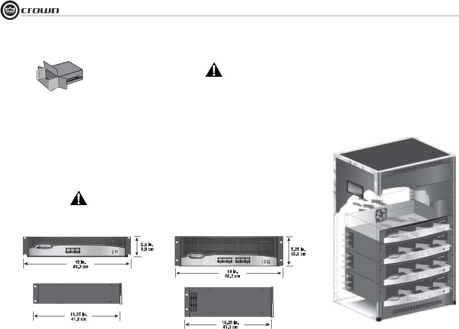
Use a standard 19-inch (48.3-cm) equipment rack (EIA RS-310B). See Figure 3.1 for amplifier dimensions.
You may also stack amps without using a cabinet.
NOTE: When transporting, amplifiers should be supported at both front and back.
Fault |
|
|
|
|
|
Thermal |
|
|
|
|
|
Clip |
|
|
|
|
Power |
Signal |
|
|
|
|
|
Ready |
|
|
|
|
Data |
1 |
Bridge |
2 |
3 |
Bridge |
4 |
Figure 3.1 Dimensions
Left: CTs 4200 Right: CTs 8200
3.3 Ensure Proper Cooling
When using an equipment rack, mount units directly on top of each other. Close any open spaces in rack with blank panels. DO NOT block front, rear or side air vents. The side walls of the rack should be a minimum of two inches (5.1 cm) away from the amplifier sides, and the back of the rack should be a minimum of four inches (10.2 cm) from the amplifier back panel.
Figure 3.2 illustrates standard amplifier airflow.
Figure 3.2 Airflow
page 6 |
Operation Manual |
CTs Multi-Channel Power Amplifiers
3 Setup
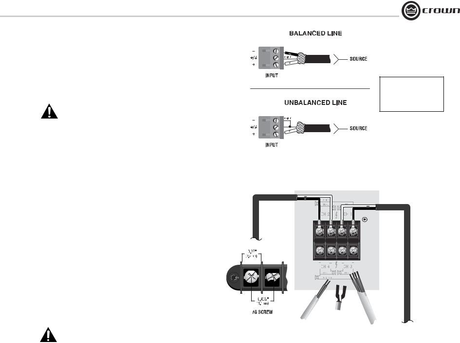
3.4 Choose Input Wire and Connectors
Figure 3.3 shows connector pin assignments for balanced wiring, and Figure 3.4 shows connector pin assignments for unbalanced wiring.
When possible, use balanced wiring for signal input, which provides better rejection of unwanted noise and hum. For more information, refer to the Crown Amplifier Application Guide, available online at www.crownaudio.com
NOTE: Custom wiring should only be performed by qualified personnel.
3.5 Choose Output Wire and Connectors
Crown recommends using professionally constructed, high-
quality, twoor four-conductor, heavy gauge speaker wire and connectors. You may use terminal forks or bare wire for your output connectors (see Figure 3.5). CTs amplifier terminal strips accept up to 10 AWG terminal forks which fit over a #8 screw. For best results, Crown recommends Panduit part #PV10-10LF-L or equivalent terminal fork. Screw spacing is shown in Figure 3.5.
To connect outputs, first remove the touch-proof cover plate covering the terminal strip by removing the screw which holds it in place.
To prevent the possibility of short-circuits, wrap or otherwise insulate exposed loudspeaker cable and connectors. Also, a touch-proof cover plate, which covers the terminal strips, is provided to help prevent short circuits. The cover plate should be reinstalled after connecting outputs.
Suggested below are guidelines to select the appropriate size of wire based on the distance from amplifier to speaker. Check with local code as this may vary.
Distance |
Wire Size |
up to 25 ft (7.6 m) |
16 AWG |
26-40 ft (7.9-12.2 m) |
14 AWG |
41-60 ft (12.5-18.3 m) |
12 AWG |
Over 60 ft (18.3 m) |
10 AWG |
CAUTION: Never connect the speaker return to the chassis of the amplifier, or damage to the amplifier may result.
CAUTION: Never use shielded cable for output wiring.
Figure 3.3 Balanced Input
Connector Wiring
See the Crown Amplifier Application Guide, available online at www.crownaudio.com, for pin assignments for commonly used connector types.
Figure 3.4 Unbalanced Input
Connector Wiring
NOTE: CTs 8200 is shown. Some CTs 4200 features are in different locations.
Output panel shown with touch-proof cover plate removed.
Figure 3.5 Output Connector Wiring
(Typical of two channels)
Operation Manual |
page 7 |

CTs Multi-Channel Power Amplifiers
3 Setup
3.6 Wire Your System
CAUTION: Never change the position of the Mode Switch while the amplifier power is on. See Section 5.2.2 for more information.
3.6.1 Dual 8/4 Mode
Typical input and output wiring, along with level control and Mode Switch settings are shown in Figure 3.6. Make sure the Mode switch is set to the “Dual 8/4” position.
INPUTS: Connect input wiring for each channel.
OUTPUTS: Maintain proper polarity (+/–) on output connectors.
Connect the Channel 1 speaker’s positive (+) lead to amplifier Channel 1 positive terminal; repeat for negative (–). Repeat each channel wiring as for Channel 1. Refer to Section 3.5 for output connector pin assignments.
BRIDGE |
|
DUAL |
DUAL |
CH 2 |
CH 1 |
CH 4 |
CH 3 |
DUAL |
DUAL |
BRIDGE |
|
Figure 3.6 System Wiring and Control Settings, Dual Mode, 8/4 Ohm
See the Crown Amplifier Application Guide, available online at www.crownaudio.com, for pin assignments for commonly used connector types.
Output panel shown with touch-proof cover plate removed.
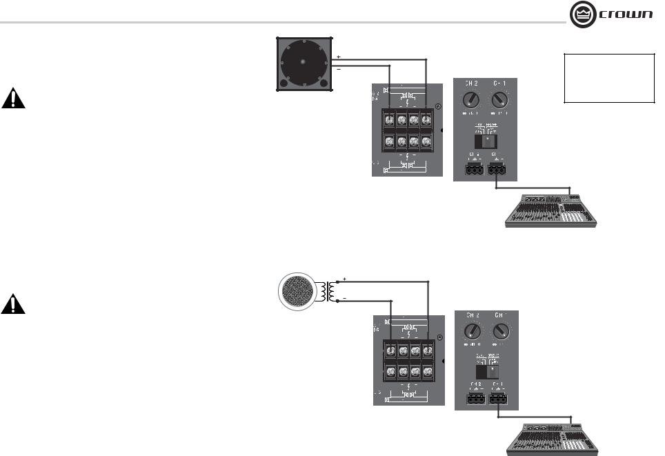
3.6.2 Dual 70V Mode
CAUTION: Never change the position of the Mode Switch while the amplifier power is on. See Section 5.2.2 for more information.
Typical input and output wiring, along with level control and Mode Switch settings are shown in Figure 3.7. Make sure the Mode switch is set to the “Dual 70V” position.
INPUTS: Connect input wiring for each channel.
OUTPUTS: Maintain proper polarity (+/–) on output connectors.
Connect Channel 1 positive (+) speaker load to Channel 1 positive terminal of amp; repeat for negative (–). Repeat each channel wiring as for Channel 1. Refer to Section 3.5 for output connector pin assignments.
70V |
|
|
|
BRIDGE |
|
|
DUAL |
DUAL |
70V |
CH 2 |
CH 1 |
|
|
Output panel |
|
|
shown with |
|
|
touch-proof |
|
|
cover plate |
|
|
removed. |
CH 4 |
CH 3 |
DUAL |
DUAL |
BRIDGE |
|
Figure 3.7 System Wiring and Control Settings, Dual Mode, 70V.
page 8 |
Operation Manual |
CTs Multi-Channel Power Amplifiers
3Setup
3.6.3Bridge-Mono 16/8 Mode
CAUTION: Never change the position of the Mode Switch while the amplifier power is on. See Section 5.2.2 for more information.
Typical input and output wiring, along with level control and Mode Switch settings are shown in Figure 3.8. Make sure the Mode switch is set to the “Bridge 16/8” position.
INPUTS: Connect input wiring only to the lower- (odd-) numbered channel pair.
OUTPUTS: Connect the speaker across the positive terminals of each channel pair. Do not use the negative terminals of the channel pair when the pair is being operated in Bridge-Mono mode.
NOTE: When operating the channel pair in Bridge-Mono mode, turn down (full CCW) the level control for the higher (even)-numbered channel of the channel pair. The lower (odd)- numbered level control works both channels.
3.6.4 Bridge-Mono 100V Mode
CAUTION: Never change the position of the Mode Switch while the amplifier power is on. See Section 5.2.2 for more information.
Typical input and output wiring, along with level control and Mode Switch settings are shown in Figure 3.9. Make sure the Mode switch is set to the “Bridge 100V” position.
INPUTS: Connect input wiring only to the lower- (odd-) numbered channel pair.
OUTPUTS: Connect the speaker across the positive terminals of each channel pair. Do not use the negative terminals of the channel pair when the pair is being operated in Bridge-Mono mode.
NOTE: When operating the channel pair in Bridge-Mono mode, turn down (full CCW) the level control for the higher (even)-numbered channel of the channel pair. The lower (odd)- numbered level control works both channels.
BRIDGE |
|
DUAL |
DUAL |
CH 2 |
CH 1 |
Output panel |
|
shown with |
|
touch-proof |
|
cover plate |
|
removed. |
|
CH 4 |
CH 3 |
DUAL |
DUAL |
BRIDGE |
|
See the Crown Amplifier Application Guide, available online at www.crownaudio.com, for pin assignments for commonly used connector types.
Figure 3.8 System Wiring and Control Settings, Bridge-Mono Mode, 16/8 Ohm.
100V |
|
|
|
BRIDGE |
|
|
DUAL |
DUAL |
|
CH 2 |
CH 1 |
Output panel |
|
|
shown with |
|
|
touch-proof |
|
|
cover plate |
|
|
removed. |
CH 4 |
CH 3 |
|
||
|
DUAL |
DUAL |
|
BRIDGE |
|
Figure 3.9 System Wiring and Control Settings, Bridge-Mono Mode, 100V
Operation Manual |
page 9 |

CTs Multi-Channel Power Amplifiers
3 Setup
3.7 Connect to AC Mains
Connect your amplifier to the AC mains power source (power outlet) with the supplied AC power cordset. First, connect the IEC end of the cordset to the IEC connector on the amplifier; then, plug the other end of the cordset to the AC mains.
WARNING: The third prong of this connector (ground) is an important safety feature. Do not attempt to disable this ground connection by using an adapter or other methods.
Amplifiers don’t create energy. The AC mains voltage and current must be sufficient to deliver the power you expect. If the AC line voltage varies out of an acceptable range, the amplifier’s power supply turns off and the blue Power LED flashes. The amplifier will turn back on when the AC line voltage returns to safe operating levels. Figure 3.10 provides voltage limits for all amplifier AC voltage configurations. Also, the amplifier must be run within the specified mains frequency requirements (indicated on the amplifier’s back panel label). If you are unsure of the output voltage of your AC mains,
please consult your electrician.
Models |
Under-Voltage |
Over-Voltage |
|
Limit |
Limit |
||
|
|||
100VAC |
90VAC |
110VAC |
|
(CTs 8200 |
|||
only) |
|
|
|
120 VAC units |
108VAC |
132VAC |
|
|
|
|
|
220V/230V/ |
198VAC |
264VAC |
|
240V units |
|||
|
|
Figure 3.10 AC Under-Voltage and Over-Voltage
Limits for Various Amplifier Models
3.8 Startup Procedure
Use the following procedure when first turning on your amplifier:
1.Turn down the level of your audio source.
2.Turn down the level controls of the amplifier.
3.Turn on the “Power” switch. The Power indicator should glow.
4.Turn up the level of your audio source to an optimum level.
5.Turn up the Level controls on the amplifier until the desired loudness or power level is achieved.
6.Turn down the level of your audio source to its normal range.
If you ever need to make any wiring or installation changes, don’t forget to disconnect the power cord.
For help with determining your system’s optimum gain structure (signal levels) please refer to the Crown Amplifier Application Guide, available online at www.crownaudio.com.
page 10 |
Operation Manual |
 Loading...