


 Loading...
Crestron QM-RMCRX-BA
QuickMedia™ Receiver/Processor
Operations Guide

This document was prepared and written by the Technical Documentation department at:
Crestron Electronics, Inc.
15 Volvo Drive
Rockleigh, NJ 07647
1-888-CRESTRON
All brand names, product names and trademarks are the property of their respective owners. ©2005 Crestron Electronics, Inc.
Crestron QM-RMCRX-BA |
QuickMedia™ Receiver/Processor |
Contents
QuickMedia™ Receiver/Processor: QM-RMCRX-BA |
1 |
Introduction .......................................................................................................... |
1 |
Features and Functions........................................................................... |
1 |
QuickMedia Transport System............................................................... |
4 |
Display Device Selection for a QuickMedia System ............................. |
6 |
Specifications ......................................................................................... |
7 |
Physical Description............................................................................... |
8 |
Memory................................................................................................ |
14 |
Industry Compliance ............................................................................ |
14 |
Setup................................................................................................................... |
15 |
Network Wiring ................................................................................... |
15 |
QM Network Wiring ............................................................................ |
16 |
Mounting.............................................................................................. |
16 |
Hardware Hookup ................................................................................ |
17 |
Ground Wire Connections.................................................................... |
19 |
Power Supply ....................................................................................... |
19 |
Crestron Toolbox ................................................................................. |
19 |
Communication Settings ...................................................................... |
20 |
Troubleshooting Communications ....................................................... |
24 |
Identity Code........................................................................................ |
26 |
Configuring the QM-RMCRX-BA..................................................................... |
28 |
Earliest Version Software Requirements for the PC ............................ |
28 |
Configuring with Crestron SystemBuilder™....................................... |
28 |
Creating a QuickMedia System in SystemBuilder............................... |
29 |
Audio and Video Adjustments ............................................................. |
32 |
Setting Network IDs in SystemBuilder ................................................ |
36 |
Example Program................................................................................. |
38 |
Problem Solving ................................................................................................. |
38 |
Troubleshooting ................................................................................... |
38 |
Further Inquiries................................................................................... |
40 |
Future Updates ..................................................................................... |
40 |
Appendix A: Programming with SIMPL Windows ........................................... |
41 |
Converting Programs and Modules Created for Other Systems........... |
62 |
Advanced Console Commands ............................................................ |
63 |
Appendix B: QuickMedia Installation and Compensation ................................. |
65 |
Installation Notes ................................................................................. |
65 |
Compensation....................................................................................... |
65 |
Compatibility Charts ............................................................................ |
67 |
Software License Agreement.............................................................................. |
69 |
Return and Warranty Policies............................................................................. |
71 |
Merchandise Returns / Repair Service ................................................. |
71 |
CRESTRON Limited Warranty ........................................................... |
71 |
Operations Guide – DOC. 6332 |
Contents • i |

Crestron QM-RMCRX-BA |
QuickMedia™ Receiver/Processor |
QuickMedia™
Receiver/Processor:
QM-RMCRX-BA
Introduction
Features and Functions
The QM-RMCRX-BA combines a Crestron® 2-Series Ethernet-based control system with a QuickMedia™ input (receiver) and Cresnet® master port. The QM-RMCRX-BA is designed to mount at the projector or plasma display to provide local display control, LAN connectivity, and signal management.
Functional Summary
•Powerful 2-Series processor, based on Motorola’s ColdFire® technology, with non-volatile memory.
•Flash memory, DRAM, and programmable logic via SIMPL Windows and SIMPL+®.
•Two bi-directional COM ports (RS-232 only).
•One IR port - compatible with Crestron ST-SPL IR-Splitter, for IRControl of up to five different devices, programmable via the hundreds of IR device drivers available in the Crestron database.
•Four digital input ports for direct connection of power sensors, pressure sensors, door sensors, room occupancy sensor, etc.
•A 10/100 Ethernet LAN port with built-in Web server/XPanel control, support for DHCP, all Crestron e-Control power applications and Crestron RoomView™ facility monitoring and management software.
Supports DHCP, DNS, SSL (refer to the notes on page 4), and XPanel IE/EXE/PDA control (Crestron e-Control®2).
•Composite, S-video and RGBHV video outputs.
•Balanced audio output, three line level outputs, and a built-in 20-watt stereo amplifier.
•Volume, bass and treble controls and a 10-band graphic/12-band parametric equalizer for left program, right program, and speech.
•Microphone mixer with up to 40 ms delay.
•Two isolated low voltage contact closure control relays.
•Power pack included.
|
|
|
Operations Guide – DOC. 6332 |
QuickMedia™ Receiver/Processor: QM-RMCRX-BA • 1 |
|
QuickMedia™ Receiver/Processor |
Crestron QM-RMCRX-BA |
The QM-RMCRX-BA processes standard video (i.e., DVD, VCR, camera video), RGB video and audio signals through its proprietary QuickMedia transport port.
The QuickMedia connection port is a revolutionary signal processing system that allows for transmitting and receiving any signal type (including video, audio, computer and microphone signals) via CAT5E type cable. A QuickMedia Wall Plate (QM-WMC), QuickMedia FlipTop box, or QuickMedia Transmitter (QM-TX) converts these signals from analog to digital and transmits them to a QM-RMCRX-BA receiver using a CAT5E cable. The QuickMedia receiver performs frequency compensation on each twisted pair video input to maintain correct operation.
The QM-RMCRX-BA then converts each of those signal types back to standard analog signals for connection to a display (projector or flat-panel monitor), an audio amplifier, or if using the on-board amplifier, directly to speakers.
QM-RMCRX-BA outputs include:
•RGBHV
•Composite video
•S-video
•Two balanced/unbalanced line audio outputs or an balanced/unbalanced stereo (left & right) line output
•One balanced/unbalanced line-level speech output
•One 20-watt stereo output (10 W per channel), with built-in volume, bass and treble controls
The QM-RMCRX-BA QuickMedia Receiver/Processor features onboard professional digital audio processing, with volume and tone control, 12-band graphic/parametric equalization, and up to 40 ms of delay for speech audio.
The onboard mic mixer can mix the two remote microphones with stereo program signals in any proportion, so the sound is always precisely tailored to the listening environment.
All the audio features of the QM-RMCRX-BA are easily configurable using Crestron SystemBuilder™ software. Using the sliders, you can adjust EQ filters and presets, input/output gain, and mixing levels. Select real time mode to hear the sound as it is adjusted and then create a configuration file ready to be uploaded to the QM-RMCRX-BA.
Video signals received by the QM-RMCRX-BA are applied to the display device via the RGBHV, S-video, and composite video ports. Each video output port is switched for signal selection to match the selected input source of the QuickMedia transmitter (sold separately). The display device can also be addressed via the COM port to activate only the input of interest. Audio path routing is accomplished via mixer schemes. Refer to the following block diagram.
2 • QuickMedia™ Receiver/Processor: QM-RMCRX-BA |
Operations Guide - DOC. 6332 |

|
Crestron QM-RMCRX-BA |
QuickMedia™ Receiver/Processor |
QM-RMCRX-BA QuickMedia Audio/Video Block Diagram |
|
|
The QM-RMCRX-BA is an Ethernet control system that runs on the powerful 2-Series processor, based on Motorola’s 32-bit ColdFire® technology. I/O options include two bi-directional COM ports, four digital inputs, two Cresnet ports, one IR port, and one 10/100 Ethernet port.
The QM-RMCRX-BA is shipped as a master controller, but may also be used as a slave. Refer to “Master-Slave Modes” in the latest version of the Crestron 2-Series Control Systems Reference Guide (Doc. 6256), available from the Crestron website (http://www.crestron.com/manuals).
The QM-RMCRX-BA provides an integrated Web server with SSL, allowing users to control AV devices from any computer on the LAN, WAN, or even custom web pages designed using Crestron VisionTools® Pro-e. With Crestron e-Control 2 XPanel technology, Web pages have the same look and feel as TPS
|
|
|
Operations Guide – DOC. 6332 |
QuickMedia™ Receiver/Processor: QM-RMCRX-BA • 3 |
|

QuickMedia™ Receiver/Processor |
Crestron QM-RMCRX-BA |
touchpanel pages, with the same outstanding runtime performance. Crestron e-Control 2 also generates standalone XPanel programs that users can launch from their Windows® desktop or from Windows PocketPC 2002 PDA devices and Windows Tablet PCs. With built-in support for SSL, users can feel confident knowing that their Crestron e-Control 2 connection to the control system is secure and private.
The QM-RMCRX-BA supports all Crestron e-Control power applications, including Crestron RoomView™ software. Using Crestron RoomView, organizations can monitor multiple room A/V controllers on an Ethernet network, in real time, from any network PC. Crestron RoomView and the QM-RMCRX-BA can provide remote power control and management of A/V devices, including monitoring lamp life of projectors, device status to ensure proper equipment operations, room occupancy, equipment use log, and device and room security.
NOTE: DHCP (Dynamic Host Configuration Protocol) is a network protocol that enables a DHCP server to automatically assign an IP address to an individual computer’s TCP/IP stack software. DHCP assigns a number dynamically from a defined range of numbers (i.e., a scope) configured for a given network.
NOTE: DNS stands for Domain Name Service (or System). Its primary use is to translate, or resolve, the IP number for a computer (e.g., 129.79.5.208) from an alphanumeric name.
NOTE: SSL, or Secure Socket Layer, is the most commonly used protocol for Web security. In addition to providing security for HTTP (Web hypertext) transactions, SSL works with other TCP/IP standards such as IMAP mail and LDAP directory access. For a security standard such as SSL to work, the browser and the Web server must both be configured to use it. SSL works by creating a temporary shared “key” that only allows the devices on either end of a transmission, to scramble and unscramble information. To anyone between the sender and the receiver, the SSL transmission is indecipherable. SSL uses certificates to verify that a device, browser or server is authentic. In addition, all data sent over an encrypted SSL connection is protected with a mechanism for detecting tampering — that is, for automatically determining whether the data has been altered in transit. Crestron’s implementation of SSL supports selfsigned certificates and certificates issued by official Internet Certifying Authorities combined with assignable security levels and password protection. Crestron SSL integration uses the RSA 1024 bit Key Exchange Algorithm with a host of cipher suites.
The QM-RMCRX-BA also provides two isolated relays for controlling low voltage contact closure devices such as drapes, screens and lifts.
QuickMedia Transport System
Using a new, proprietary signal routing solution, signals such as composite video, S-video, RGBHV, audio, and microphone are all transported using a single cable solution called QuickMedia (QM).
The QM transport system port is capable of managing computer, video, and audio signals simultaneously through one CAT5E or CAT6 UTP (unshielded twisted pair) wire, simplifying installations.
Routing CAT5E or CAT6 UTP cable is less expensive and much simpler than routing multi-colored, multi-conductor coax cable. All Crestron products using the QM transport system are capable of sending and receiving QM signals via
4 • QuickMedia™ Receiver/Processor: QM-RMCRX-BA |
Operations Guide - DOC. 6332 |
Crestron QM-RMCRX-BA |
QuickMedia™ Receiver/Processor |
standard CAT5E or CAT6 cable. Installation of any QM device is as simple as installing one set of QM wires from output to input. Installations are flexible, affordable, and fast.
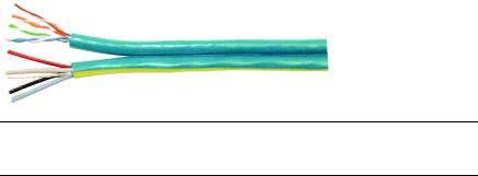
The Crestron QuickMedia cable “CRESCAT-QM” contains one CAT5E cable and one Cresnet® cable in siamese jackets.
CRESCAT-QM Cable
NOTE: Do not untwist the two wires in a single pair for more than 1/3-1/2" (0.84 – 1.27 cm) when making a connection. The twists are critical to canceling out interference between the wires.
The QuickMedia transport mechanism performs delay compensation on each video input to compensate for signal skew, and frequency/bandwidth compensation for cable length. Signal skew occurs when part of the signal is delayed with respect to other signal components. The amount of skew largely depends on the length and design of the wire. Because CAT5 consists of twisted pairs that are twisted together in the cable, unequal wire lengths are created.
The maximum aggregate cable length from QM transmitter to QM receiver is limited by the loss of bandwidth over long distances and the amount of available skew compensation. A cable rated at 15 ns of skew per 100 meters (328 ft.) means that a cable will have no more than a 15 ns difference between the fastest and slowest RGB signals over 100 meters of cable.
To determine the allowable maximum length of installed cable, the installer must first perform a calculation based on the skew rating of the cable. The use of low-resolution signals may allow increased cable length but must be tested with the sources to be used. To ensure sufficient bandwidth to support signal resolutions up to 1600 x 1200, the maximum aggregate cable length should not exceed 328 feet.
Skew compensation is primarily relevant to RGB sources; however, any/all video or VGA signals may experience a loss of quality over very long lengths of cable. This phenomenon is due to the added resistance and capacitance of longer cable lengths, and is not particular to either Crestron and/or QuickMedia systems.
Refer to Appendix B on page 65 for additional QuickMedia information.
The pin assignment is based on the EIA/TIA 568B RJ-45 Jack standard. The following table illustrates how composite, S-video, and RGB video signals are transmitted over the CAT5E wire.
|
|
|
Operations Guide – DOC. 6332 |
QuickMedia™ Receiver/Processor: QM-RMCRX-BA • 5 |
|
|
QuickMedia™ Receiver/Processor |
Crestron QM-RMCRX-BA |
|
|||||
RJ-45 QuickMedia Connector Pin Assignments |
|
|
|
|
|
|
||
|
|
|
|
|
|
|
|
|
|
|
RJ-45 PIN |
|
WIRE COLORS |
QM ASSIGNMENT |
|
QM ASSIGNMENT |
|
|
|
NUMBER |
|
(EIA 568B) |
RGB AND AUDIO |
|
COMPOSITE, |
|
|
|
|
|
|
|
S-VIDEO AND AUDIO |
|
|
|
|
|
|
|
|
|
|
|
|
1 |
|
WHITE/ORANGE |
- RGB RED |
|
- CHROMINANCE |
|
|
|
|
|
|
|
|
|
|
|
|
2 |
|
ORANGE |
+ RGB RED |
|
+ CHROMINANCE |
|
|
|
3 |
|
WHITE/GREEN |
- RGB GREEN |
|
- LUMINANCE |
|
|
|
4 |
|
BLUE |
+ AUDIO |
|
+ AUDIO |
|
|
|
5 |
|
WHITE/BLUE |
- AUDIO |
|
- AUDIO |
|
|
|
|
|
|
|
|
|
|
|
|
6 |
|
GREEN |
+ RGB GREEN |
|
+ LUMINANCE |
|
|
|
7 |
|
WHITE/BROWN |
- RGB BLUE |
|
- COMPOSITE |
|
|
|
8 |
|
BROWN |
+ RGB BLUE |
|
+ COMPOSITE |
|
|
|
|
|
|
|
|
|
|
|
Display Device Selection for a QuickMedia
System
QuickMedia fully integrates the display device with the system. Consequently, careful selection of a display device is required to take full advantage of this capability. A projector should support discrete video switching commands. This enables the QuickMedia receiver/processor to seamlessly pass along the three different video types to the display and alert the display to switch inputs.
In addition, the display device should support discrete power on and off commands. This enables a system “Room On” button function that will energize the display. If the display device has a toggle on/off power command, there is a possibility of getting out of sync with the room power. Most RS-232 display drivers in the Crestron database support discrete commands. Refer to the Crestron Database in System Builder or the Dealer/Tech Resources | Whose Products Do We Control? Section of the Crestron website for a list of products. You may search by manufacturer or device type. You may also call the Crestron customer service team or check our online help system for the latest information.
6 • QuickMedia™ Receiver/Processor: QM-RMCRX-BA |
Operations Guide - DOC. 6332 |
Crestron QM-RMCRX-BA |
QuickMedia™ Receiver/Processor |
Specifications
Specifications for the QM-RMCRX-BA are given in the following table.
QM-RMCRX-BA Specifications
SPECIFICATION |
DETAILS |
|
|
CPU |
32-Bit Motorola 5272 ColdFire® Processor |
Processor Speed |
63 MIPS (Dhrystone 2.1 Benchmark) |
Memory |
36 MB (4 MB Flash, 32 MB SDRAM, 256 KB NVRAM)1 |
Power Usage |
36 Watts (1.6 A @ 24 VDC) |
|
50 W external power pack (PW-2420RU) included |
Initial Firmware Release |
3.146 |
Default Network ID |
02 (Shipped as a control system master) |
Ports/Connectors2 |
|
LAN |
One RJ-45 10/100 BaseT, full duplex Ethernet port |
|
Default IP Ports: 80 = HTTP/Web Host, |
|
41794 = Crestron, 41795 = Diagnostics/Toolbox |
IR (Infrared) |
One 2-position mini serial output connector (supports |
|
up to five IR devices) |
INPUT |
One 5-position mini digital connector (four inputs plus |
|
ground) |
COM (A & B) |
Two DB9 bidirectional RS-232 serial ports, baud rate up |
|
to 115,200 bps (Port B is used for initial communication |
|
and setup) |
24 VDC, 2A |
One DC receptacle for included external power pack |
CRESNET |
Two 4-pin mini connectors for Cresnet system |
VIDEO |
One BNC male connector for composite video output |
S-VIDEO |
One mini-DIN 4-pin connector for S-video output |
RGBHV |
One D15HD female connector for RGBHV output |
AUDIO |
One 9-pin connector for balanced/unbalanced line-level |
|
left, right and speech audio output |
SPEAKER |
Two 2-pin connector for amplified left and right audio |
|
output |
QM |
One RJ-45 QuickMedia input connector |
RELAY OUTPUT |
Two 2-pin mini connectors for relay operation |
Reset Buttons |
|
HW-R |
Initiates system hardware reset |
SW-R |
SIMPL Windows program restart (if held at startup, |
|
bypasses program) |
Composite/S-Video |
|
Video Gain |
0 dB (unity, double termination) |
Bandwidth |
>100 MHz (- 3 dB) at unity gain |
RGB Video |
|
Gain |
0 dB (unity, double termination) |
Maximum |
1600 x 1200 @ 60 Hz, at unity gain, with maximum |
resolution/Refresh Rate |
compensation at receiver |
H and V Sync |
5 V p-p maximum, 100 Ω impedance |
Bandwidth Compensation |
Digital control, 10-bit D/A |
Digital Gain Control |
10-bit D/A (low frequency compensation) |
Propagation Delay |
Digitally controlled delay line (4-bit control) |
Compensation |
|
Maximum Compensation |
22 ns (for R, G, or B independently) |
Continued on the following page
1.For more information on system memory usage, refer to “Memory” on page 13.
2.For more information on controls, ports, and indicators, refer to “Physical Description” on page 8.
|
|
|
Operations Guide – DOC. 6332 |
QuickMedia™ Receiver/Processor: QM-RMCRX-BA • 7 |
|
QuickMedia™ Receiver/Processor |
|
Crestron QM-RMCRX-BA |
|
|
|
QM-RMCRX-BA Specifications (continued) |
|
||
|
|
|
|
|
|
SPECIFICATION |
DETAILS |
|
|
|
|
|
|
|
|
Audio line-level channels |
|
|
|
|
Maximum Line-Level |
4 VRMS per channel balanced |
|
|
|
Output |
2 VRMS per channel unbalanced |
|
|
|
Output Impedance |
200 Ω balanced |
|
|
|
|
100 Ω unbalanced |
|
|
|
Frequency Response |
20 |
Hz to 20 kHz +/- 0.5 dB |
|
|
Signal-to-Noise Ratio |
20 |
Hz to 20 kHz A-weighted 92 dB |
|
|
Total Harmonic Distortion |
20 |
Hz to 20 kHz 0.02% |
|
|
Audio Amplifier Output |
|
|
|
|
Amplified Audio |
10 |
W maximum per channel into 4 or 8 Ω |
|
|
Frequency Response |
20 |
Hz to 20 kHz +/- 0.5 dB |
|
|
Signal-to-Noise Ratio |
20 |
Hz to 20 kHz A-weighted 90 dB |
|
|
Total Harmonic Distortion |
20 |
Hz to 20 kHz 0.02% |
|
|
Audio Switcher Processing |
|
|
|
|
Volume Control |
-80 dB to +20 dB unbalanced input & output |
|
|
|
Bass/Treble Controls |
+/- 15 dB |
|
|
|
Selectable Equalization |
3-band graphic plus 9-band parametric EQ |
|
|
|
|
5-band graphic plus 7-band parametric EQ |
|
|
|
|
5-band graphic plus 7-band parametric with speech |
|
|
|
|
optimization EQ |
|
|
|
|
10-band graphic plus 2-band parametric EQ |
|
|
|
|
Full 12-band parametric EQ (no graphic equalizers) |
|
|
|
Environmental Temperature |
41° to 104° (5° to 40°C) |
|
|
|
Environmental Humidity |
10% to 90% RH (non-condensing) |
|
|
|
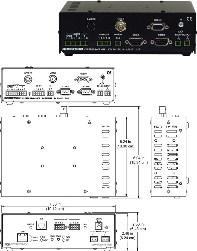
Dimensions |
Height: 2.53 in (6.43 cm) |
|
|
|
|
Width: 7.53 in (19.12 cm) |
|
|
|
|
Depth: 6.04 in (15.34 cm) |
|
|
|
Weight |
1.70 lbs (0.77 kg) |
|
|
Physical Description
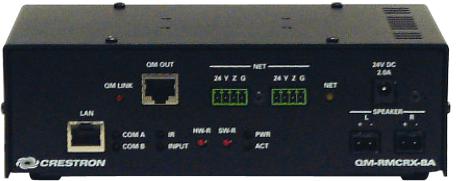
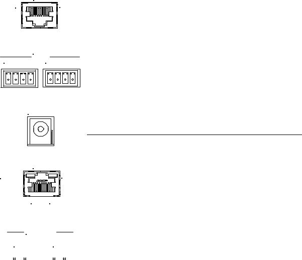
The QM-RMCRX-BA is housed in a black enclosure with labeling on the front and rear panels. There are four rubber feet on the base of the unit for stability and to prevent slippage. Refer to the following illustrations and physical views.
QM-RMCRX-BA Front View
8 • QuickMedia™ Receiver/Processor: QM-RMCRX-BA |
Operations Guide - DOC. 6332 |
Crestron QM-RMCRX-BA |
QuickMedia™ Receiver/Processor |
QM-RMCRX-BA Rear View |
|
Physical Dimensions
|
|
|
Operations Guide – DOC. 6332 |
QuickMedia™ Receiver/Processor: QM-RMCRX-BA • 9 |
|
QuickMedia™ Receiver/Processor |
Crestron QM-RMCRX-BA |
|||
|
|
|
Front Panel Ports |
|
|
|
|
The QM-RMCRX-BA front panel ports are illustrated and described as follows. |
|
1 |
Q M |
8 |
QM Input |
|
|
|
|||
|
|
|
||
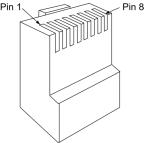
The eight-pin RJ-45 QuickMedia transport port accepts CAT5E audio, video, microphone, and control signals. The QM input port conforms to the 568B wiring standard. The associated QM LINK LED indicates a QM connection. Refer to page 16 for network wiring information and refer to page 6 for pinouts.
NET
24 Y Z G 24 Y Z G
24VDC
2.0A
LAN
Yellow |
Green |
8 1
|
L |
SPEAKER |
|||||
|
|
|
|
|
R |
||
+ - |
+ - |
|
|||||
|
|
|
|
|
|
|
|
|
|
|
|
|
|
|
|
|
|
|
|
|
|
|
|
|
|
|
|
|
|
|
|
|
|
|
|
|
|
|
|
NET
These connectors are used for expansion to Cresnet peripherals. Power to the unit can be supplied through this connector. The associated NET LED indicates network activity.
24VDC, 2.0A (Power Supply Input)
This male connector can be used to supply 24 VDC power to the QM-RMCRX-BA from an external power pack (included).
CAUTION: Use only Crestron power supplies for Crestron equipment. Failure to do so could cause equipment damage or void the Crestron warranty.
LAN
An 8-position RJ-45 port (labeled LAN) is used for connection to the Ethernet, providing local area network or Web access (cable is not supplied). The port also contains two light-emitting diodes (LEDs). The green LED on the right side of the port is a link status LED and illuminates when the card is connected to a working network. The yellow LED on the left side flashes to indicate Ethernet activity. Refer to page 22 for Ethernet cabling details.
SPEAKER
The speaker output consists of two 2-pin terminal block connectors, 5 mm spacing. These connectors have left and right amplified stereo audio output, 10 watts per channel into 4 or 8 ohms.
10 • QuickMedia™ Receiver/Processor: QM-RMCRX-BA |
Operations Guide - DOC. 6332 |
Crestron QM-RMCRX-BA |
QuickMedia™ Receiver/Processor |
|
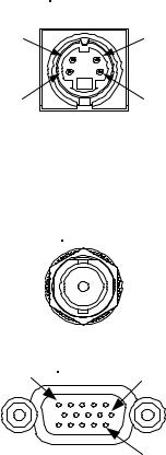
S-VIDEO |
Pin 4 |
Pin 3 |
Pin 2 |
Pin 1 |
Rear Panel Ports
The QM-RMCRX-BA rear panel ports are illustrated and described as follows.
S-Video
One DIN type connector is provided for S-video output. S-video contains two separate components, luminance and chrominance (also known as Y and C signals respectively). The luminance signal contains brightness, intensity, and signal timing information. This signal contains all picture information except for color. The chrominance signal contains only the color information. You can see the complete black and white image, without the chrominance, by only feeding the luminance signal into a monitor.
S-Video Connector Pinout
PIN |
DESCRIPTION |
|
|
1 |
Ground |
2 |
Ground |
3 |
Luminance |
4 |
Chrominance |
|
|
VIDEO
1 RGBHV 10
15
Composite Video
One BNC type connector is provided for composite video output.
Composite video is a type of video signal in which all of the video information, the red, green, and blue (horizontal and vertical sync) signals are mixed together.
RGBHV
One DB15HD male connector is provided for RGB video output (also supports component video).
DB15HD Connector Pinout
PIN |
DESCRIPTION |
PIN |
DESCRIPTION |
|
|
|
|
1 |
Red Signal |
9 |
N/C |
2 |
Green Signal |
10 |
Sync Ground |
3 |
Blue Signal |
11 |
ID0 (Ground) |
4 |
Reserved |
12 |
ID1 (No Connection) |
5 |
Ground |
13 |
Horizontal Sync |
6 |
Red Ground |
14 |
Vertical Sync |
7 |
Green Ground |
15 |
No Connection |
8 |
Blue Ground |
|
|
RGB is a computer signal that uses the standard High Density (HD-15) 15-pin connector. It is comprised of three analog video signals: red, green, blue and separate horizontal and vertical syncs. Most computer monitors use RGB (usually called VGA, SVGA, XVGA, etc.). RGBHV consists of red, green, blue, horizontal sync and vertical sync.
|
|
|
Operations Guide – DOC. 6332 |
QuickMedia™ Receiver/Processor: QM-RMCRX-BA • 11 |
|
QuickMedia™ Receiver/Processor |
Crestron QM-RMCRX-BA |
INPUT
1 2 3 4 G
IR
S G
COM A |
COM B |
Audio Line Level (Outputs)
One 9-pin mini connector provides three balanced/unbalanced line level outputs: Speech (SPCH), Left (L) and Right (R).
Maximum line-level output: 4 VRMS per channel balanced, 2 VRMS per channel unbalanced.
INPUT
This 5-pin connector provides four software programmable digital inputs plus ground. The inputs are Schmidt trigger type (nominal 2.5 V threshold) with 24 V input tolerance.
Digital inputs are rated 0 – 24 VDC, 20K ohms input impedance.
IR
The 2-position mini-connector is a mini-implementation of a single PRO2 IR port. The output is labeled S (signal) and G (ground), for controlling devices via IR or one-way RS-232. (Depending on the control format, additional equipment such as IR emitters, splitters, receivers, and remote control transmitters may be required).
Infrared output is rated up to 1.2 MHz. Serial protocol is one-way RS-232.
COM (A & B)
These two DB9 (male) software programmable, bi-directional serial ports are available for RS-232 communication, with hardware and software handshaking and modem control. Speeds are rated up to 115,200 bps. COM B can also be used as the console port.
A null modem cable is required to connect to a computer.
NOTE: RS-422 and RS-485 are not supported.
Standard COM DB9 Pinout
PIN |
DIRECTION |
DESCRIPTION |
|
|
|
1 |
TO QM-RMCRX-BA |
(DCD) Data Carrier Detect |
|
|
|
2 |
To QM-RMCRX-BA |
(RXD) Receive Data |
3 |
From QM-RMCRX-BA |
(TXD) Transmit Data |
4 |
From QM-RMCRX-BA |
(DTR) Data Terminal Ready |
5 |
Common |
(SG) Signal Ground |
6 |
From QM-RMCRX-BA |
(DSR) Data Set Ready |
7 |
From QM-RMCRX-BA |
(RTS) Request To Send |
|
|
|
8 |
To QM-RMCRX-BA |
(CTS) Clear To Send |
9 |
To QM-RMCRX-BA |
(RI) Ring Indicator |
|
|
|
12 • QuickMedia™ Receiver/Processor: QM-RMCRX-BA |
Operations Guide - DOC. 6332 |

Crestron QM-RMCRX-BA |
QuickMedia™ Receiver/Processor |
RELAY OUTPUT
Two 2-pin isolated relay connectors are provided for controlling low voltage contact closure devices such as drapes, screens and lifts. Each connector is rated 2 A @ 50 V.
Indicators
The QM-RMCRX-BA front panel indicators are described as follows.
QM LINK
This LED indicates an established QuickMedia link.
COM A
This red LED indicates COM A port activity.
COM B
This red LED indicates COM B port activity. Constant blinking indicates that the port is used for remote console connection.
IR
This red LED indicates IR port activity.
INPUT
This red LED indicates input activity.
PWR (Power)
This green LED illuminates when the unit is connected to and receives 24 VDC power from an external power pack or from Cresnet.
ACT (LAN)
This yellow activity LED illuminates when the QM-RMCRX-BA detects
Crestron Ethernet traffic (i.e., XPanel™).
NET (Cresnet)
This yellow LED illuminates when the QM-RMCRX-BA communicates with Cresnet devices on the network, and also indicates that the SIMPL Windows program currently loaded has a network device defined at the same network ID as the QM-RMCRX-BA.
Reset Buttons
Two buttons are provided on the front panel of the QM-RMCRX-BA. Refer to the following descriptions.
HW-R
Pressing this button initiates system hardware reset. (Same effect as disconnecting and reconnecting power.)
|
|
|
Operations Guide – DOC. 6332 |
QuickMedia™ Receiver/Processor: QM-RMCRX-BA • 13 |
|

QuickMedia™ Receiver/Processor |
Crestron QM-RMCRX-BA |
SW-R
Pressing this button in combination with the HW-R button performs a system restart without loading the program (refer to “Establishing Console Mode on an Ethernet Slave” on page 24). Press HW-R momentarily while pressing and holding SW-R to reboot.
Pressing SW-R alone while the system is running restarts the program.
Serial console connection may be established if SW-R button is pressed and held about five to seven seconds during power up (wait for Toolbox to display some information), or if pressed and held at the same time HW-R is momentarily pressed. The serial console mode is also established if the processor is configured as a master, but has no program loaded. In this way, the console mode is enabled out-of-the-box and the user does not have to perform any special steps to initially configure the processor.
NOTE: The COM B LED will flash when in the console mode.
To terminate the console mode, press the HW-R button or cycle the power.
NOTE: Pressing <F10> (Program Reset) in Toolbox may cause errors if both the program and the console mode are using the same COM port.
Memory
The QM-RMCRX-BA has 36 MB of built-in memory (non-volatile and volatile). The total of 36 MB is specified as follows: 4 MB flash (non-volatile), 32 MB SDRAM (volatile), and 256 KB NVRAM (battery backed up). Flash memory contains the file system inside the 2-Series control engine. Non-volatile memory contains information that is retained after the loss of electrical power. Volatile memory is lost after a power failure.
The 4 MB flash memory consists of approximately 1.5 MB used for firmware, and approximately 2.5 MB available for SIMPL, SIMPL+, and Web pages. The files that reside in flash conform to a flat directory structure.
1.SIMPL Program (.smw)
2.SIMPL+ Modules (.usp/.ush)
3.Operating System (.cuz file)
Refer to the 2-Series Control Systems Reference Guide (Doc. 6256) for additional memory structure information.
Industry Compliance
As of the date of manufacture, the QM-RMCRX-BA has been tested and found to comply with specifications for CE marking and standards per EMC and Radiocommunications Compliance Labelling.
NOTE: This device complies with part 15 of the FCC rules. Operation is subject to the following two conditions: (1) this device may not cause harmful interference, and (2) this device must accept any interference received, including interference that may cause undesired operation.
14 • QuickMedia™ Receiver/Processor: QM-RMCRX-BA |
Operations Guide - DOC. 6332 |
Crestron QM-RMCRX-BA |
QuickMedia™ Receiver/Processor |
Setup
Network Wiring
CAUTION: In order to ensure optimum performance over the full range of your installation topology, Crestron Certified Wire, and only Crestron Certified Wire, should be used. Failure to do so, may incur additional charges if support is required to identify performance deficiencies as a result of using improper wire.
CAUTION: Provide sufficient power to the system. Insufficient power can lead to unpredictable results or damage to the equipment. Please use the Crestron Power Calculator to help calculate how much power is needed for the system (http://www.crestron.com/calculators).
CAUTION: Use only Crestron power supplies for Crestron equipment. Failure to do so could cause equipment damage or void the Crestron warranty.
NOTE: When installing network wiring, refer to the latest revision of the wiring diagram(s) appropriate for your specific system configuration, available from the Crestron website.
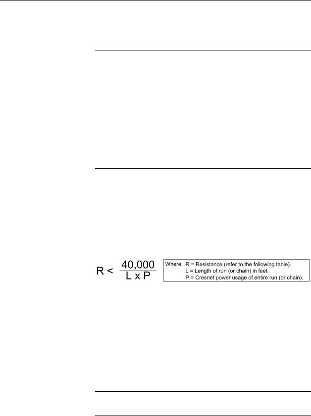
When calculating the wire gauge for a particular Cresnet run, the length of the run and the Cresnet power usage of each network unit to be connected must be taken into consideration. If Cresnet units are to be daisy-chained on the run, the Cresnet power usage of each unit to be daisy-chained must be added together to determine the Cresnet power usage of the entire chain. If the unit is a home-run from a Crestron system power supply network port, the Cresnet power usage of that unit is the Cresnet power usage of the entire run. The length of the run in feet and the Cresnet power usage of the run should be used in the resistance equation below to calculate the value on the right side of the equation.
Resistance Equation
The required wire gauge should be chosen such that the resistance value is less than the value calculated in the resistance equation. Refer to the following table.
Wire Gauge Values
RESISTANCE |
WIRE GAUGE |
|
|
4 |
16 |
6 |
18 |
10 |
20 |
15 |
22 |
13 |
Doubled CAT5 |
|
|
8.7 |
Tripled CAT5 |
|
|
NOTE: All Cresnet wiring must consist of two twisted pairs. One twisted pair is the +24V conductor and the GND conductor, and the other twisted pair is the Y conductor and the Z conductor.
|
|
|
Operations Guide – DOC. 6332 |
QuickMedia™ Receiver/Processor: QM-RMCRX-BA • 15 |
|
QuickMedia™ Receiver/Processor |
Crestron QM-RMCRX-BA |
NOTE: When daisy-chaining Cresnet units, strip the ends of the wires carefully to avoid nicking the conductors. Twist together the ends of the wires that share a pin on the network connector, and tin the twisted connection. Apply solder only to the ends of the twisted wires. Avoid tinning too far up the wires or the end becomes brittle. Insert the tinned connection into the Cresnet connector and tighten the retaining screw. Repeat the procedure for the other three conductors.
NOTE: For additional information on video connections over CAT5, refer to the latest version of the Crestron CAT5 Wiring Reference Guide (Doc. 6137) which is available from Crestron website (http://www.crestron.com/manuals).
NOTE: For larger networks (i.e., greater than 28 network devices), it may be necessary to add a Cresnet Hub/Repeater (CNXHUB) to maintain signal quality throughout the network. Also, for networks with lengthy cable runs or varying types of network devices, it may be desirable to add a hub/repeater after only 20 network devices.
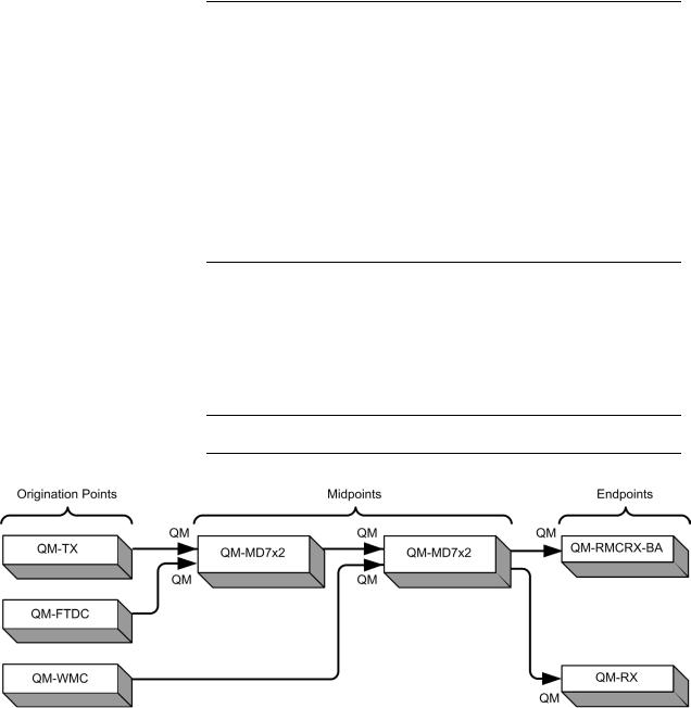
QM Network Wiring
When connecting multiple QM devices, the route between a QM origination point (e.g., QM-TX) and a QM endpoint (e.g., QM-RMCRX-BA) cannot have more than two midpoints (e.g., QM-MD7x2 or other QM switchers). Refer to the following diagram when configuring a QM network. The aggregate length from transmitter to receiver cannot have a delay skew of more than 22 ns.
NOTE: Refer to Appendix B on page 65 for detailed auto-compensation information.
QM Network Topology
Mounting
The QM-RMCRX-BA can be mounted using the included four mounting brackets. Attach the included brackets using the existing cover screws located on the sides of the QM-RMCRX-BA as shown in the following diagram.
16 • QuickMedia™ Receiver/Processor: QM-RMCRX-BA |
Operations Guide - DOC. 6332 |
|
Crestron QM-RMCRX-BA |
QuickMedia™ Receiver/Processor |
Mounting Positions of the Four Included Mounting Brackets |
|
|
NOTE: The MK-QM-RMCRX mounting kit is available for mounting the
QM-RMCRX-BA to a pipe. Details can be found in the latest version of the
MK-QM-RMCRX Installation Guide (Doc. 6247).
Hardware Hookup
Refer to the following hookup diagram and, aside from attaching power last, complete the connections in any order.
NOTE: To prevent overheating, do not operate this product in an area that exceeds the environmental temperature range listed in the specifications table. Consideration must be given if installed in a closed or multi-unit rack assembly since the operating ambient temperature of the rack environment may be greater than the room ambient. Contact with thermal insulating materials should be avoided on all sides of the unit.
NOTE: The maximum continuous current from equipment under any external load conditions shall not exceed a current limit that is suitable for the minimum wire gauge used in interconnecting cables. The ratings on the connecting unit's supply input should be considered to prevent overloading the wiring.
|
|
|
Operations Guide – DOC. 6332 |
QuickMedia™ Receiver/Processor: QM-RMCRX-BA • 17 |
|

QuickMedia™ Receiver/Processor |
Crestron QM-RMCRX-BA |
Front Connections |
|
Rear Connections
NOTE: COM B is shared for device control and serial console connection.
NOTE: Use either the internal amplifier (SPEAKER) output or the AUDIO left and right line outputs, but not both. Using both induces noise.
18 • QuickMedia™ Receiver/Processor: QM-RMCRX-BA |
Operations Guide - DOC. 6332 |
Crestron QM-RMCRX-BA |
QuickMedia™ Receiver/Processor |
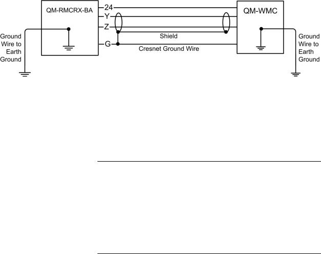
Ground Wire Connections
Proper grounding is required. Connect the ground from the QM peripheral (in this example a QM-WMC) to earth ground. Connect the Cresnet shield lead at the QM-RMCRX-BA control processor to the ground lead. The control processor chassis must also be connected to an earth ground (building steel). Refer to the following grounding diagram.
Grounding Diagram
Power Supply
The QM-RMCRX-BA can be powered through the NET network connector (Cresnet), or by the external PW-2420 power pack (50W) included but not by both methods. Use the provided external power pack to provide power to peripheral Cresnet devices (via the Cresnet connector).
If additional power is needed, Crestron recommends its CNPWS-75 (75 watts) external power supply.
CAUTION: Use only Crestron power supplies for Crestron equipment. Failure to do so could cause equipment damage or void the warranty.
NOTE: Use care in wiring installations to avoid applying 24 VDC power to Cresnet wiring from an external power pack as well as from a system device that contains its own power supply. Although this condition should not cause any damage, Crestron does not recommend it.
NOTE: In larger system configurations that require more power than supplied by Cresnet, disconnect the +24 VDC wire from the QM-RMCRX-BA Cresnet connector and provide the +24 VDC power to the peripheral devices by an alternate Crestron power source.
Crestron Toolbox
The Crestron Toolbox (replacement for Crestron Viewport, you may continue to use Viewport if desired) is a broad-based software package that accomplishes multiple system tasks, primarily using an RS-232 or TCP/IP connection between a PC and one or more Crestron control systems.
You can use the Crestron Toolbox to:
•Observe system processes.
•Upload operating systems and firmware.
•Upload programs and touchpanel projects.
•Set or change device Network IDs.
|
|
|
Operations Guide – DOC. 6332 |
QuickMedia™ Receiver/Processor: QM-RMCRX-BA • 19 |
|
Loading...