


 Loading...
Crestron Isys® TPS-4L
3.6-Inch Wall Mount Touchpanel
Operations & Installation Guide

This document was prepared and written by the Technical Documentation department at:
Crestron Electronics, Inc.
15 Volvo Drive
Rockleigh, NJ 07647
1-888-CRESTRON
All brand names, product names and trademarks are the property of their respective owners. ©2006 Crestron Electronics, Inc.
Crestron Isys® TPS-4L |
3.6-inch Wall Mount Touchpanel |
Contents
3.6-Inch Wall Mount Touchpanel: TPS-4L |
1 |
Introduction .......................................................................................................... |
1 |
Features and Functions........................................................................... |
1 |
Specifications ......................................................................................... |
2 |
Physical Description............................................................................... |
3 |
Industry Compliance .............................................................................. |
5 |
Setup..................................................................................................................... |
6 |
Network Wiring ..................................................................................... |
6 |
Identity Code.......................................................................................... |
6 |
Mounting Options .................................................................................. |
8 |
Touchpanel Mounting ............................................................................ |
9 |
Touchpanel Removal ........................................................................... |
12 |
Hardware Hookup ................................................................................ |
13 |
Configuring the Touchpanel................................................................. |
13 |
Programming Software....................................................................................... |
16 |
Earliest Version Software Requirements for the PC ............................ |
16 |
Programming with Crestron SystemBuilder ........................................ |
17 |
Programming with SIMPL Windows................................................... |
17 |
Programming with VT Pro-e................................................................ |
19 |
Example Program................................................................................. |
20 |
Uploading and Upgrading .................................................................................. |
20 |
Establishing Communications.............................................................. |
20 |
Troubleshooting Communications ....................................................... |
28 |
Uploading a SIMPL Windows Program .............................................. |
28 |
Upgrading Firmware ............................................................................ |
30 |
Uploading VT Pro-e Projects ............................................................... |
33 |
Uploading Firmware & VT Pro-e Projects Via TCP/IP....................... |
33 |
Problem Solving ................................................................................................. |
35 |
Further Inquiries................................................................................... |
35 |
Future Updates ..................................................................................... |
35 |
Software License Agreement.............................................................................. |
36 |
Return and Warranty Policies............................................................................. |
38 |
Merchandise Returns / Repair Service ................................................. |
38 |
CRESTRON Limited Warranty ........................................................... |
38 |
Operations & Installation Guide – DOC. 6449 |
Contents • i |

Crestron Isys® TPS-4L |
3.6-Inch Wall Mount Touchpanel |
3.6-Inch Wall Mount Touchpanel:
TPS-4L
Introduction
Features and Functions
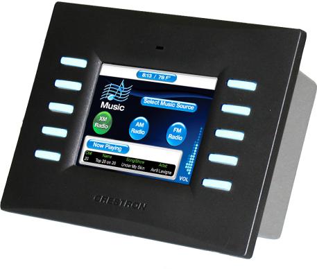
The TPS-4L compact touchpanel, is a 3.6-inch (9.15 cm) active matrix color display panel with 320 x 240 resolution and 16-bit non-palette Isys® graphics that provides user interface to a Crestron® remote control system (Cresnet® system).
These wall panels offer an ideal means of controlling everything from audio distribution to complete home automation, permitting creation of custom control screens perfectly tailored to meet the needs of the end-user.
Functional Summary
•Integrated 3.6 in (9.15 cm) active matrix color display
•16-bit Isys graphics
•320 x 240 screen resolution
•Synapse image rendering algorithm
•10 translucent white backlit pushbuttons*
•WAV file audio feedback
•Cresnet and Ethernet communications
•8 MB of flash (approx. 7MB for user display lists)
•16 MB of DRAM (Dynamic RAM) for panel firmware
•Stylish flush-mount design for walls, lectern, or similar mounting surfaces
*As an option, a custom-engraved bezel can be designed and obtained by using the Crestron Engraver software. Version 2.6.1.0 and Crestron Database 17.6.0 or later are available from the Crestron website (www.crestron.com).
The bright, 3.6-inch active-matrix color touchscreen provides a fully customizable user interface for control of AV, lighting, screens, volume and more. With 16-bit Isys graphics, the TPS-4L produces high-quality graphics, dynamic text, and fullmotion animations complete with WAV file audio feedback. The touchpanel also supports dynamic graphics and multi-mode objects. Ten programmable pushbuttons
|
|
|
|
Operations & Installation Guide – DOC. 6449 |
3.6-inch Wall Mount Touchpanel: Isys® TPS-4L • 1 |
||

3.6-Inch Wall Mount Touchpanel |
Crestron Isys® TPS-4L |
are also included featuring translucent buttons with white LED backlighting and an engravable faceplate.
The units support both Cresnet and Ethernet protocols for communication with other devices as well as uploading programs and firmware.
The TPS-4L touchpanel bezel (sold separately) is available in a variety of colors (e.g., white, almond, and black). Contact a Crestron customer service representative for details.
NOTE: The TPS-4L is compatible with 2-Series control systems only.
Specifications
Specifications for the TPS-4L are given in the following table.
TPS-4L Specifications
SPECIFICATION |
DETAILS |
|
|
Cresnet Power Usage |
5 Watts (0.21 Amp @ 24 VDC) |
Default Network ID |
03 |
Firmware |
tps-4l_c2n-ft-tps-4_qm-ftcc-tps_tps-4_2.007.0163 or later |
2-Series Control System |
Version 3.137.CUZ or later |
Update Files1,2 |
|
Connectors |
|
LAN |
(1) 8-Wire RJ-45 with 2 LED indicators |
Cresnet |
(1) 4-pin terminal block |
|
|
Touchpanel Display |
|
Display Type |
Active matrix color LCD |
Size |
3.6 in (9.1 cm) |
Resolution |
320 x 240 pixels maximum |
Colors |
64,000 (16 bits) |
Illumination |
LED 300 cd/m² |
Contrast ratio |
300:1 typical |
Viewing angle |
±80° typical horizontal, +80°/-50° typical vertical |
Touchscreen |
Resistive membrane |
Touchpanel Processor |
|
CPU |
32-bit Freescale Coldfire Microprocessor |
Processing Speed |
96 MIPS |
Touchpanel Memory |
8MB internal flash; 16MB DRAM |
Touchpanel Ethernet |
|
Support |
10/100Base-T Full duplex, Link and Activity LEDs |
Operating Temperature and |
41º to 104º F (5º to 40º C) |
Humidity |
10 to 90% relative humidity |
|
(non-condensing) |
Dimensions and Weight |
Width: 6.19 in (15.72 cm) |
|
Height: 4.53 in (11.51 cm) |
|
Depth: 2.11 in (5.36 cm) |
|
Weight: 15 oz (0.43 kg) |
1.The latest software versions can be obtained from the Crestron website. Refer to the NOTE following these footnotes.
2.Crestron 2-Series control systems include the AV2 and PRO2. Consult the latest Crestron Product Catalog for a complete list of 2-Series control systems.
NOTE: Crestron software and any files on the website are for Authorized Crestron dealers and Crestron Authorized Independent Programmers (CAIP) only. New users may be required to register to obtain access to certain areas of the site (including the FTP site).
|
|
|
|
2 • 3.6-inch Wall Mount Touchpanel: Isys® TPS-4L |
Operations & Installation Guide - DOC. 6449 |
||
Crestron Isys® TPS-4L |
3.6-inch Wall Mount Touchpanel |
Physical Description
Refer to the physical views shown below and on subsequent pages.
TPS-4L Shown in Black
Operations & Installation Guide – DOC. 6449 |
3.6-inch Wall Mount Touchpanel: Isys® TPS-4L • 3 |
3.6-Inch Wall Mount Touchpanel |
Crestron Isys® TPS-4L |
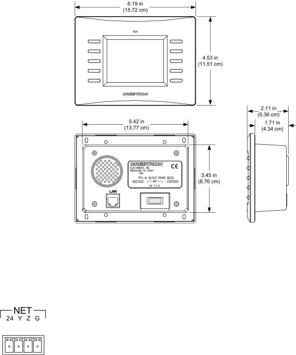
TPS-4L Physical Dimensions |
|
Controls and Ports
Buttons
The TPS-4L touchpanel has 10 hard buttons; five on each side of the display. The buttons are backlit with white LEDs; brightness is program adjustable. The buttons can be programmed to automate frequently used functions.
NET
This 4-pin terminal block connector provides communication with and power from a Cresnet control network. For more information, refer to “Network Wiring” on page 6.
Pins 24 and G provide 24 VDC and ground; pins Y and Z provide communications (data). Note that the connector pin identification is printed on the unit label above it.
Reset
A hardware reset button is located behind the bezel as shown in the following graphic. This button is used as a last resort to reboot the touchpanel (similar to cycling power) in the unlikely event that the touchpanel hangs up.
|
|
|
|
4 • 3.6-inch Wall Mount Touchpanel: Isys® TPS-4L |
Operations & Installation Guide - DOC. 6449 |
||

Crestron Isys® TPS-4L |
3.6-inch Wall Mount Touchpanel |
Reset
Button
LAN
Yellow |
Green |
LED |
LED |
1 |
8 |
To access the reset button, remove the bezel and then use a narrow blunt instrument such as the end of a ballpoint pen to press the button.
CAUTION: Do not attempt to press the reset button by inserting a paperclip or similar device through the small hole in the bezel. This could cause physical damage to the button or a short circuit on the printed circuit board.
LAN
An 8-wire RJ-45 connector with two LED indicators (green LED indicates link status, yellow LED indicates Ethernet activity). This connector provides an Ethernet 10baseT /100baseTX, full duplex, TCP/IP, UDP/IP, CIP, IEEE 802.3U compliant network connection for the TPS-4L touchpanel.
NOTE: This port does not support a wireless Ethernet connection.
LAN Connector Pinout
PIN |
SIGNALS |
|
PIN |
SIGNALS |
|
|
|
|
|
1 |
TX + |
5 |
N/C |
|
2 |
TX - |
|
6 |
RC - |
3 |
RC+ |
7 |
N/C |
|
4 |
N/C |
|
8 |
N/C |
Industry Compliance
As of the date of manufacture, the TPS-4L has been tested and found to comply with specifications for CE marking and standards per EMC and Radiocommunications Compliance Labelling.
NOTE: This device complies with part 15 of the FCC rules. Operation is subject to the following two conditions: (1) this device may not cause harmful interference, and
(2) this device must accept any interference received, including interference that may cause undesired operation.
Operations & Installation Guide – DOC. 6449 |
3.6-inch Wall Mount Touchpanel: Isys® TPS-4L • 5 |

3.6-Inch Wall Mount Touchpanel |
Crestron Isys® TPS-4L |
Setup
Network Wiring
CAUTION: In order to ensure optimum performance over the full range of your installation topology, Crestron Certified Wire, and only Crestron Certified Wire, may be used. Failure to do so may incur additional charges if support is required to identify performance deficiencies as a result of using improper wire.
CAUTION: Use only Crestron power supplies for Crestron equipment. Failure to do so could cause equipment damage or void the Crestron warranty.
CAUTION: Provide sufficient power to the system. Insufficient power can lead to unpredictable results or damage to the equipment. Please use the Crestron Power Calculator to help calculate how much power is needed for the system (http://www.crestron.com/calculators).
When calculating the length of wire for a particular Cresnet run, the wire gauge and the 84000-56z Cresnet power usage of each network unit to be connected must be taken into consideration. Use Crestron Certified Wire only. If Cresnet units are to be daisy-chained on the run, the Cresnet power usage of each network unit to be daisychained must be added together to determine the Cresnet power usage of the entire chain. If the unit is a home-run from a Crestron system power supply network port, the Cresnet power usage of that unit is the Cresnet power usage of the entire run. The wire gauge and the Cresnet power usage of the run should be used in the following equation to calculate the cable length value on the equation’s left side.
Cable Length Equation
L < |
40,000 |
Where: L = Length of run (or chain) in feet. |
R x P |
R = 6 Ohms (Crestron Certified Wire: 18 AWG (0.75 MM2)) |
|
|
P = Cresnet power usage of entire run (or chain). |
Make sure the cable length value is less than the value calculated on the right side of the equation. For example, a Cresnet run drawing 20 watts should not have a length of run more than 333 feet.
NOTE: All Crestron certified Cresnet wiring must consist of two twisted pairs. One twisted pair is the +24V conductor and the GND conductor, and the other twisted pair is the Y conductor and the Z conductor.
NOTE: When daisy-chaining Cresnet units, strip the ends of the wires carefully to avoid nicking the conductors. Twist together the ends of the wires that share a pin on the network connector, and tin the twisted connection. Apply solder only to the ends of the twisted wires. Avoid tinning too far up the wires or the end becomes brittle. Insert the tinned connection into the Cresnet connector and tighten the retaining screw. Repeat the procedure for the other three conductors.
NOTE: For larger networks (i.e., greater than 28 network devices), it may become necessary to add a Cresnet Hub/Repeater (CNXHUB) to maintain signal quality throughout the network. Also, for networks with lengthy cable runs, it may be necessary to add a Hub/Repeater after only 20 devices.
Identity Code
Every piece of equipment and user interface within the network requires a unique identity code (Net ID). These codes are two-digit hexadecimal numbers from 03 to
|
|
|
|
6 • 3.6-inch Wall Mount Touchpanel: Isys® TPS-4L |
Operations & Installation Guide - DOC. 6449 |
||
Crestron Isys® TPS-4L |
3.6-inch Wall Mount Touchpanel |
FE (Net ID 02 is reserved for master control units). The Net IDs reside within all Cresnet devices (hardware) and must match the Net ID as specified in the software (SIMPL Windows) that runs the system. Refer to “Setting the Net ID in Device Settings” on page 19 for details of the SIMPL Windows procedure.
The Net ID of the TPS-4L has been factory set to 03. The Net IDs of multiple TPS-4Ls in the same system must be unique. Net IDs can be changed from a personal computer (PC) using Crestron SystemBuilder™ or Crestron Toolbox, or through the device SETUP MENU as described on page 14.
NOTE: For detailed information on establishing communication between the PC and control system, refer to “Establishing Communications” on page 20. If communication cannot be established, refer to the “Troubleshooting Communications” section in the latest version of the 2-Series Control System Reference Guide (Doc. 6256), which is available from the Crestron website (http://www.crestron.com/manuals).
The Crestron Toolbox provides several methods to easily set or change device Net
IDs for any device on the network. The following method permits you to change the
Net ID of any device in the network through the “Network Device Tree” window.
NOTE: This method prevents you from setting duplicate IDs.
This method permits you to manually set the Net ID for any device in the network, can be used to set any known Net IDs that may require changing, and may also be used for non-TSID equipment. This method will not permit you to choose an ID already in use by another device. A warning message will appear if you attempt to use an ID that is already in use.
Duplicate Net ID Warning Message
This method does not change the Net ID as assigned in SIMPL windows. Refer to page 19 for the SIMPL Windows ID change procedure.
NOTE: You may also use Crestron SystemBuilder to perform Network ID setup.
1.Ensure that all network devices are connected to the control system.
2.Open Crestron Toolbox and establish communications (refer to page 20).
3.Select the Network Device Tree  icon, or select Tools | Network Device Tree. (Refer to the following figure.)
Operations & Installation Guide – DOC. 6449 |
3.6-inch Wall Mount Touchpanel: Isys® TPS-4L • 7 |

3.6-Inch Wall Mount Touchpanel |
Crestron Isys® TPS-4L |
Network Device Tree |
|
4.Click on the ‘+’ next to the name of the device to display its current Net ID setting, and then right-click on the Net ID you wish to change. When the sub-menu appears, select Change Network ID.
Network Device Tree – Sub-Menu
5.The current Net ID is highlighted. Enter a new Net ID and press Enter.
Enter New Net ID
6.An alert message appears to notify you that the change was successful.
7.Repeat this procedure for each network device requiring a Net ID change.
Mounting Options
The TPS-4L touchpanel installs simply and cleanly into existing or newly constructed walls, with an assortment of preand post-construction mounting options. The TPS-4L is supplied with four screws and clips for post-construction installation. All available mounting options are listed in the following table. (The Wall Mount Kit – Bracket, Model WMKB-4L, consists of multiple sets of clips like the ones supplied.)
|
|
|
|
8 • 3.6-inch Wall Mount Touchpanel: Isys® TPS-4L |
Operations & Installation Guide - DOC. 6449 |
||

Crestron Isys® TPS-4L |
3.6-inch Wall Mount Touchpanel |
NOTE: Refer to the latest version of the supplied Touchpanel Mounting Quick Start guide, Doc. 6140, for details about the available mounting options before starting any actual installation procedures.
Mounting Options for the TPS-4L
PRE- |
POST- |
MODEL |
DOCUMENT |
CONSTRUCTION |
CONSTRUCTION |
NUMBER |
NUMBER |
OPTION |
OPTION |
|
|
Back Box Kit |
- |
BB-4L |
6387 |
Pre-Construction |
- |
PMK-4L |
6388 |
Mount Kit |
|
|
|
Mud Ring Mount Kit |
- |
MMK-4L |
6389 |
(Accessory) |
|
|
|
Trim Ring Mount Kit |
- |
TMK-4L |
6390 |
(Accessory) |
|
|
|
- |
Wall Mount Kit – Mud |
WMKM-4L |
6389 |
|
Ring |
|
|
|
|
|
|
- |
Wall Mount Kit – Trim |
WMKT-4L |
6390 |
|
Ring |
|
|
|
Wall Mount Kit – Bracket |
WMKB-4L |
Not Applicable |
|
|
|
|
NOTE: Pre-construction refers to framed walls prior to hanging drywall.
Post-construction refers to framed walls with drywall hung.
Touchpanel Mounting
Physical installation of the TPS-4L includes mounting the unit to the wall and installing an engraved touchpanel bezel. The only tools required for the procedures presented here are masking tape (or equivalent), a gypsum board saw (or equivalent), and a #2 Phillips tip screwdriver. The following procedures are based on the use of the supplied screws and clips for post-construction installation.
Mounting to the Wall
The TPS-4L is designed to be mounted in a wall or lectern. Two overlay cutout templates (0V40078) are supplied. One is in the shape of the required opening; the other is similar to a frame, with the inner area of the frame the shape of the required opening. (Refer to the following diagrams.) Use the template that is most convenient.
Mounting Parts Supplied with the TPS-4L
PART DESCRIPTION |
QUANTITY |
|
|
Screw #6 x 2-½”, Pan Head |
4 |
Mounting Clip |
4 |
Overlay Template Cutout |
1 |
|
|
Four-pin Connector Plug |
1 |
|
|
NOTE: The following drawings are not to scale. Do not attempt to use them to prepare the hole in the mounting surface.
Operations & Installation Guide – DOC. 6449 |
3.6-inch Wall Mount Touchpanel: Isys® TPS-4L • 9 |

3.6-Inch Wall Mount Touchpanel |
Crestron Isys® TPS-4L |
TPS-4L Cutout Dimensions (4007478, 1 of 2) |
|
TPS-4L Cutout Dimensions (4007478, 2 of 2)
1.Locate an area on the wall that is free of miscellaneous wiring and studs.
2.Make a small hole near the middle of the designated site, and verify that the location is suitable.
3.Using masking tape (or equivalent), fasten the template to the wall; verify that the template is level, and trace the opening shape on the wall.
|
|
|
|
10 • 3.6-inch Wall Mount Touchpanel: Isys® TPS-4L |
Operations & Installation Guide - DOC. 6449 |
||
Loading...