


 Loading...
Crestron CLS/CLSI-C6 & CLS/CLSI-C6M
iLux™ Lighting System
Operations Guide

This document was prepared and written by the Technical Documentation department at:
Crestron Electronics, Inc.
15 Volvo Drive
Rockleigh, NJ 07647
1-888-CRESTRON
All brand names, product names and trademarks are the property of their respective owners. ©2006 Crestron Electronics, Inc.
Crestron CLS/CLSI-C6 & CLS/CLSI-C6M |
iLux™ Lighting System |
Contents
iLux™ Lighting System: CLS/CLSI-C6 & CLS/CLSI-C6M |
1 |
Introduction ............................................................................................................................... |
1 |
Features and Functions................................................................................................ |
1 |
Specifications .............................................................................................................. |
4 |
Physical Description.................................................................................................... |
4 |
Industry Compliance ................................................................................................... |
8 |
Setup .......................................................................................................................................... |
9 |
Network Wiring........................................................................................................... |
9 |
Identity Code ............................................................................................................... |
9 |
Installation................................................................................................................... |
9 |
Hardware Hookup ..................................................................................................... |
11 |
Adding External Power Supplies............................................................................... |
11 |
Configuring the CLS-C6.......................................................................................................... |
12 |
Configuring With Front Panel Controls .................................................................... |
12 |
Configuring With iLux Designer............................................................................... |
21 |
Console Command Settings ...................................................................................... |
23 |
Replacing the Function Button Label........................................................................ |
24 |
Programming Software............................................................................................................ |
26 |
Earliest Version Software Requirements for the PC ................................................. |
26 |
Programming with Crestron SystemBuilder/D3 Pro ................................................. |
26 |
Programming with SIMPL Windows ........................................................................ |
27 |
Example Program ...................................................................................................... |
28 |
Uploading and Upgrading........................................................................................................ |
29 |
Establishing Communication..................................................................................... |
29 |
Programs and Firmware ............................................................................................ |
29 |
Operation ................................................................................................................................. |
31 |
Button Types ............................................................................................................. |
31 |
IR Receiver................................................................................................................ |
33 |
Occupancy Sensing ................................................................................................... |
34 |
Problem Solving ...................................................................................................................... |
37 |
Troubleshooting......................................................................................................... |
37 |
Check Network Wiring.............................................................................................. |
37 |
Reference Documents................................................................................................ |
38 |
Further Inquiries ........................................................................................................ |
38 |
Future Updates .......................................................................................................... |
39 |
Appendix A: Supported Devices ............................................................................................. |
40 |
Keypads..................................................................................................................... |
40 |
Shade Controllers ...................................................................................................... |
40 |
Appendix B: Console Commands............................................................................................ |
41 |
Appendix C: Factory Default Values....................................................................................... |
45 |
Appendix D: Button Functions ................................................................................................ |
46 |
Software License Agreement................................................................................................... |
53 |
Return and Warranty Policies .................................................................................................. |
55 |
Merchandise Returns / Repair Service ...................................................................... |
55 |
CRESTRON Limited Warranty................................................................................. |
55 |
Operations Guide - DOC. 6347B |
Contents • i |

Crestron CLS/CLSI-C6 & CLS/CLSI-C6M |
iLux™ Lighting System |
iLux™ Lighting System:
CLS/CLSI-C6 & CLS/CLSI-C6M
Introduction
Features and Functions
•Wall-mounted integrated lighting and shade control
•Six channels of dimming or switching
•Six groups of shade or drape control
•Linkable for up to 54 lighting channels and 54 shade groups
•Up to 16 user-settable scenes | Large ON and OFF buttons
•Seven configurable “rocker” buttons with customizable label strip
•Flip-up front cover reveals setup controls and programming port
•Six bargraphs show lighting levels and shade positions
•Easy setup from front panel or iLux Designer software
•Built-in motion detector (CLS/CLSI-C6M) | Optional IR remote
•Supports multipoint control using up to 16 keypads
•Master air-gap relay | 230V AC version available
•Integrates with 2-Series control systems via Cresnet
•Available in almond, black, or white
Six Channel Dimming
The CLS-C6 features six channels of dimming for incandescent, magnetic lowvoltage, neon/cold cathode, and two-wire dimmable fluorescent loads. Each channel can also support switching of many non-dimmable lighting loads. Each channel will handle up to 800 watts individually, with a total rating for the complete unit of 1920 watts at 120 VAC for CLS-C6/C6M (2300 watts at 230 VAC for CLSI-C6/C6M).
Operations Guide - DOC. 6347B |
iLux™ Lighting System: CLS/CLSI-C6 & CLS/CLSI-C6M • 1 |
iLux™ Lighting System |
Crestron CLS/CLSI-C6 & CLS/CLSI-C6M |
Six Group Shade Control
Using Crestron’s networked shade and drape controllers (sold separately), the CLS-C6 enables versatile control of a roomful of motorized window treatments, screens, and lifts in up to six shade groups. Each controller is connected to the CLS-C6 via the four-wire Cresnet bus.
Versatile Front Panel Controls
The deceptively clean front panel actually affords an extensive amount of control and customization to suit each unique room application. Large ON and OFF buttons provide instant access to the “On” and “All Off” scenes, while the six main buttons can be set up to recall additional scene presets, adjust shades, or perform a host of other functions. The buttons' “rocker” action enables intuitive control for adjusting lighting levels and shade positions. An additional "Up/Down” button is configurable for a variety of functions, including use as a master lighting or shade control, or as a "shift" button to expand the capabilities of the six main buttons.
With each new scene selection, window shades reposition and lights fade elegantly to their new settings. The selected scene is indicated by a white LED beside each button, and the customizable label strip allows each button to be clearly labeled using Crestron Engraver software. Dimming levels and shade positions are displayed graphically on six green LED bargraphs accessible behind the flip-up front cover. Additional controls and a numeric display hidden beneath the cover enable setup without requiring a PC. Enhanced customization is provided via the PC programming port using iLux Designer software.
Built-in Motion Detector (CLS/CLSI-C6M)
The CLS/CLSI-C6M model provides the addition of a built-in infrared motion detector, enabling automated control based on room occupancy. Lights can be programmed to turn on and shades open automatically when someone enters the room, or turn off and close when the room is left empty. Remote motion detectors are also available to expand the coverage of the CLS/CLSI-C6M, or add occupancy sensing capability to the CLS-C6 units.
IR Remote Control
The CLS-C6 units are equipped with an onboard IR receiver to allow for wireless remote control using Crestron’s optional infrared remote control (sold separately).
Multipoint Keypad Control
Up to 16 Crestron keypads (sold separately) may be connected to a single CLS-C6, providing versatile multipoint control for rooms with several entrances or work areas.
Multi-Unit Expansion
A single CLS-C6 master will support up to eight additional CLS-C6s, enabling systems of up to 54 lighting channels and 54 shade groups. Scene recall, master dimming, and occupancy status are shared between all the CLS-C6 units. Each individual unit can still support a complete assortment of local devices including keypads, shade controllers, and sensors.
|
2 |
• iLux™ Lighting System: CLS/CLSI-C6 & CLS/CLSI-C6M |
Operations Guide - DOC. 6347B |
Crestron CLS/CLSI-C6 & CLS/CLSI-C6M |
iLux™ Lighting System |
Control System Integration
The CLS-C6 actually features two separate Cresnet control networks, one for local devices and one for connection to a 2-Series control system.
Connecting the CLS-C6 to a control system allows its functions to be controlled from touchpanels, RF wireless remotes, and even computers, supporting extensive flexibility for remote control and integration with other devices and systems.
Additional functions such as on-the-fly room combining and activating operations based on a real-time clock are also made possible by connecting the CLS-C6 to a control system.
Connecting to an Ethernet-networked control system provides a gateway to larger applications such as integration with facility-wide lighting, HVAC, security, and remote monitoring via Crestron RoomView® Help Desk software as well as thirdparty SNMP software.
Operations Guide - DOC. 6347B |
iLux™ Lighting System: CLS/CLSI-C6 & CLS/CLSI-C6M • 3 |
iLux™ Lighting System |
Crestron CLS/CLSI-C6 & CLS/CLSI-C6M |
Specifications
The following table provides specifications for the CLS-C6.
CLS-C6 Specifications
SPECIFICATION |
DETAILS |
|
|
Load Ratings CLS-C6/C6M
Max load per channel : Min load per channel Max load per unit:
CLSI-C6/C6M
Max load per channel : Min load per channel Max load per unit:
Power Requirements
Default Net ID
Control System Update Files 1, 2
Minimum 2-Series Control
System
Load Types
IR Receiver
Reception Frequency
Motion Detector (CLS/CLSI-C6M only
Type
Range
Firmware
Environmental Temperature
Humidity
Overall Dimensions:
Height
Width
Depth
Weight
800 W/VA (6.7 Amps @ 120 VAC)
15 W/VA (0.125 Amps @ 120 VAC)
1920 W/VA (16 Amps @ 120 VAC)
800 W/VA (3.5 Amps @ 230 VAC)
25 W/VA (0.108 Amps @ 230 VAC)
2300 W/VA (10 Amps @ 230 VAC)
CLS-C6 Line Power, 100 –127 VAC, 50 / 60Hz CLSI-C6 Line Power, 220 – 240 VAC, 50 / 60Hz
1F
Version 2.004.CUZ or later
Incandescent, magnetic low voltage, neon/cold cathode, dimmable 2-wire fluorescent, and non-dim lighting (also: electronic low voltage, 3-wire and 4-wire fluorescent3)
36 kHz
Requires Crestron IR remote (sold separately).
Infrared
20 to 30 feet at 4-foot elevation
(6 to 9 meters at 1.2 meter elevation)
clsi-c6_clsi-c6m_1.01.02.upg or later
32° to 104°F (0° to 40°C)
10% to 90% RH (non-condensing)
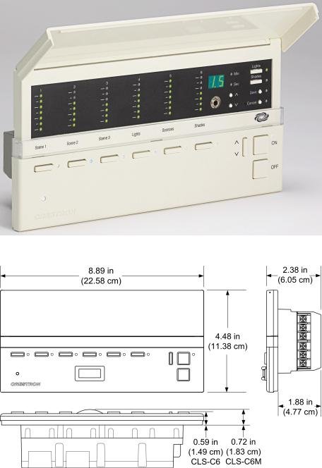
4.48 in (11.38 cm)
8.89 in (22.58 cm)
2.46 in (6.25 cm) for CLS/CLSI-C6
2.59 in (6.58 cm) for CLS/CLSI-C6M
1.43 lbs (0.65 kg)
1.The latest versions can be obtained from the Crestron website. Refer to NOTE after last footnote.
2.Crestron 2-Series control systems include the AV2 and PRO2. Consult the latest Crestron Product Catalog for a complete list of 2-Series control systems.
3.These loads require an optional booster module. The modules are LEPB-n, where ‘n’ is a number based on the desired load type. Also, some boosters permit control of 277VAC loads. Refer to the Crestron website for details on power boosters.
NOTE: Crestron software and any files on the website are for Authorized Crestron dealers and Crestron Authorized Independent Programmers (CAIP) only. New users may be required to register to obtain access to certain areas of the site (including the FTP site).
Physical Description
All controls and indicators for the CLS-C6 are located on the front of the unit. The front panel also contains a mini phone jack, under the flip-up cover, used for programming functions, and an IR port for control via an IR remote device. All other
|
4 |
• iLux™ Lighting System: CLS/CLSI-C6 & CLS/CLSI-C6M |
Operations Guide - DOC. 6347B |
Crestron CLS/CLSI-C6 & CLS/CLSI-C6M |
iLux™ Lighting System |
ports and connectors are located on the rear panel. Refer to the table “Connectors, Controls, & Indicators” on page 6 for details.
CLS-C6 (Cover Open)
CLS-C6/C6M Overall Dimensions
Operations Guide - DOC. 6347B |
iLux™ Lighting System: CLS/CLSI-C6 & CLS/CLSI-C6M • 5 |
iLux™ Lighting System Crestron CLS/CLSI-C6 & CLS/CLSI-C6M
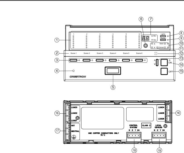
CLS-C6/CLS-C6M Front Panel
CLS-C6/CLS-C6M Rear Panel
Connectors, Controls, & Indicators
# |
CONNECTORS, |
DESCRIPTION |
|
CONTROLS, & |
|
|
INDICATORS |
|
1 |
Bargraphs |
In Standard mode and Lights mode, the bargraphs, |
|
|
each a series of seven LEDs, indicate the current |
|
|
light intensity for the six lighting loads. In Shades |
|
|
mode, they indicate the shade position for each of |
|
|
the shade groups. The bargraphs have other |
|
|
functions in Setup mode. |
2 |
Label Strip |
Customizable label for the six scenes. |
3 |
Function Buttons and LEDs |
In Standard mode, these buttons are typically used |
|
|
to select/recall scenes. In Lights mode, they are |
|
|
used to make temporary adjustments to the six |
|
|
lighting loads. In Shades mode they are used to |
|
|
make temporary adjustments to the shade groups. |
|
|
They can also be programmed to perform other |
|
|
functions. |
4 |
IR Detector |
The IR detector responds to commands from the |
|
|
optional Crestron remote control. The remote |
|
|
control can be used to recall Scenes 1 – 4, the On |
|
|
and Off scenes, and perform master raise and lower |
|
|
of the lighting loads. |
Continued on next page
|
6 |
• iLux™ Lighting System: CLS/CLSI-C6 & CLS/CLSI-C6M |
Operations Guide - DOC. 6347B |
Crestron CLS/CLSI-C6 & CLS/CLSI-C6M |
iLux™ Lighting System |
||||||
|
Connectors, Controls, & Indicators (continued) |
|
|
|
|
||
|
|
|
|
|
|
|
|
|
# |
CONNECTORS, |
|
|
DESCRIPTION |
||
|
|
CONTROLS, & |
|
|
|
|
|
|
|
INDICATORS |
|
|
|
|
|
|
5 |
Motion Detector (CLS/CLSI- |
The built-in motion detector can be used to activate |
||||
|
|
C6M only) |
a particular scene when there is activity in the room, |
||||
|
|
|
and/or to activate a particular scene (typically Off) |
||||
|
|
|
when there is no activity for a specified period. A |
||||
|
|
|
limited number of actions are available when |
||||
|
|
|
programmed locally; more are available using the |
||||
|
|
|
iLux Designer software program. |
||||
|
6 |
Mini Phone Jack |
Use this 3.5mm TRS mini-phone jack, located on |
||||
|
|
|
the front panel, as an RS-232 programming port, to |
||||
|
|
|
communicate with the iLux Designer and Crestron |
||||
|
|
|
Toolbox to configure the unit, and to upgrade the |
||||
|
|
|
unit’s firmware. |
||||
|
7 |
Two-Digit Display |
In Standard mode, the display is normally blank, |
||||
|
|
|
except when showing scene fade time. The Min and |
||||
|
|
|
Sec LEDs illuminate when the display is indicating |
||||
|
|
|
time in minutes or in seconds, respectively. In Setup |
||||
|
|
|
mode, the display uses a two-character mnemonic |
||||
|
|
|
to indicate which specific aspect of the CLS-C6 you |
||||
|
|
|
are changing. As these are being adjusted, the |
||||
|
|
|
display may indicate values. (Refer to “Setup Mode” |
||||
|
|
|
on page 13 for details.) |
||||
|
8 |
Lights Pushbutton and LED |
Use this switch to select the Lights mode. The LED |
||||
|
|
|
illuminates when the mode is selected. Refer to |
||||
|
|
|
“Lights Mode” |
on page 34 for details. |
|||
|
9 |
Shades Pushbutton and |
Use this switch to select the Shades mode. The |
||||
|
|
LED |
LED illuminates when the mode is selected. Refer |
||||
|
|
|
to “Shades Mode” on page 35 for details. |
||||
|
10 |
^, v, Save, and Cancel |
Use these pushbuttons to navigate and execute |
||||
|
|
Pushbuttons |
setup functions. The Save and Cancel LEDs |
||||
|
|
|
indicate when these functions are active. Refer to |
||||
|
|
|
“Setup Mode” on page 13 for details. |
||||
|
11 |
Reset Button |
If the unit stops functioning and does not respond to |
||||
|
|
|
button pushes, use a thin object such as a paperclip |
||||
|
|
|
to activate this switch. The unit reboots (all lighting |
||||
|
|
|
loads go off, the two-digit display shows “– –,” and |
||||
|
|
|
all lighting loads go to their previous state). |
||||
|
|
|
|
|
|
||
|
12 |
Shift LEDs |
These LEDs are covered by the label strip, but are |
||||
|
|
|
easily visible through the strip when they are |
||||
|
|
|
illuminated. When the Shift mode is enabled via |
||||
|
|
|
programming, there can be two functions defined for |
||||
|
|
|
each of the six function buttons. The unit will always |
||||
|
|
|
be in “upper” or “lower” shift mode as indicated by |
||||
|
|
|
the state of the LEDs. |
||||
|
13 |
Up/Down Pushbutton |
This three position “rocker” switch is programmable |
||||
|
|
|
for master lights control (all lights or last scene), |
||||
|
|
|
master shade control, or as a “shift” button to allow |
||||
|
|
|
a second set of functions for the six function |
||||
|
|
|
buttons. |
|
|
|
|
|
14 |
ON Button |
The ON button always acts as a recall scene button |
||||
|
|
|
for the “On” scene. Refer to |
“Standard Mode” |
On |
||
|
|
|
page 31 for details. |
|
|
||
|
15 |
OFF Button |
The OFF button always acts as a recall scene |
||||
|
|
|
button for the Off scene, which will always turn all |
||||
|
|
|
lighting loads off and open the air-gap relay. Refer |
||||
|
|
|
to “Standard Mode” On page 31 for details. |
||||
Continued on next page
Operations Guide - DOC. 6347B |
iLux™ Lighting System: CLS/CLSI-C6 & CLS/CLSI-C6M • 7 |
iLux™ Lighting System |
Crestron CLS/CLSI-C6 & CLS/CLSI-C6M |
|||
|
Connectors, Controls, & Indicators (continued) |
|
||
|
|
|
|
|
# |
CONNECTORS, |
|
DESCRIPTION |
|
|
|
CONTROLS, & |
|
|
|
|
INDICATORS |
|
|
16 LOAD1 – LOAD6
17 |
HOT, NEUTRAL, |
((Ground) |
18CONTROL SYSTEM
19LOCAL DEVICES
Use these terminals to connect the CLS-C6 dimmer channel outputs to the appropriate lighting loads.
Use these terminals to connect the unit to the 120V (CLS-C6/M) or 230V (CLSI-C6/M) AC power source.
Use this 4-pin terminal block to connect the CLSC6, using standard Cresnet wiring, to a 2-Series control system network. In this configuration, the CLS-C6 acts as a standard Cresnet slave device. (The CLS-C6 does not draw power from Cresnet.)
Use this 4-pin terminal block to connect the CLSC6, using standard Cresnet wiring, to local devices. In this configuration, the CLS-C6 acts as the Cresnet Master (Net ID 02).
Industry Compliance
This product is listed to applicable UL Standards and requirements by Underwriters Laboratories Inc.
(E103692)
As of the date of manufacture, the CLS-C6 has been tested and found to comply with specifications for CE marking and standards per EMC and Radiocommunications Compliance Labelling.
NOTE: This device complies with part 15 of the FCC rules. Operation is subject to the following two conditions: (1) this device may not cause harmful interference, and
(2) this device must accept any interference received, including interference that may cause undesired operation.
This equipment has been tested and found to comply with the limits for a Class B digital device, pursuant to part 15 of the FCC Rules. These limits are designed to provide reasonable protection against harmful interference in a residential installation. This equipment generates, uses and can radiate radio frequency energy and, if not installed and used in accordance with the instructions, may cause harmful interference to radio communications. However, there is no guarantee that interference will not occur in a particular installation. If this equipment does cause harmful interference to radio or television reception, which can be determined by turning the equipment off and on, the user is encouraged to try to correct the interference by one or more of the following measures:
Reorient or relocate the receiving antenna.
Increase the separation between the equipment and receiver.
Connect the equipment into an outlet on a circuit different from that to which the receiver is connected.
Consult the dealer or an experienced radio/TV technician for help.
|
8 |
• iLux™ Lighting System: CLS/CLSI-C6 & CLS/CLSI-C6M |
Operations Guide - DOC. 6347B |

Crestron CLS/CLSI-C6 & CLS/CLSI-C6M |
iLux™ Lighting System |
Setup
As stated earlier, the CLS-C6 features two separate Cresnet control networks: one for local devices and one for connection to a 2-Series control system. When connected to a control system, the CLS-C6 acts as a standard Cresnet slave device. When local devices are connected to it, the CLS-C6 acts as the Cresnet Master (Net ID 02). In some configurations, the unit serves a dual role. (Refer to the configuration examples included in “Identity Code” below for more details.)
The following wiring information applies to a 2-Series control system network. The CONTROL SYSTEM port of the CLS-C6 may be connected to this network.
Network Wiring
When wiring the network, consider the following:
•Use Crestron Certified Wire.
•Use Crestron power supplies for Crestron equipment.
•Provide sufficient power to the system.
CAUTION: Insufficient power can lead to unpredictable results or damage to the equipment. Please use the Crestron Power Calculator to help calculate how much power is needed for the system (http://www.crestron.com/calculators).
•For larger networks, Use a Cresnet Hub/Repeater (CNXHUB) to maintain signal quality.
For more details, refer to “Check Network Wiring” on page 37.
Identity Code
The Net ID of the CLS-C6 has been factory set to 1F. The Net IDs of multiple CLS-C6 devices in the same system must be unique. Net IDs are changed from a personal computer (PC) via the Crestron Toolbox™ or iLux Designer software programs. When setting the Net ID, consider the following:
•The Net ID of each unit must match an ID code specified in the SIMPL Windows program.
•Each network device must have a unique Net ID.
For more details, refer to the Crestron Toolbox or iLux Designer help files.
Installation
Detailed installation procedures are provided in the latest version of the Crestron iLux Lighting Systems Installation Guide (Doc. 6394 for CLS-C6/C6M; Doc. 6413 for CLSI-C6/C6M).
The figure on the following page illustrates five installation configurations and includes brief descriptions of the rationale behind each one.
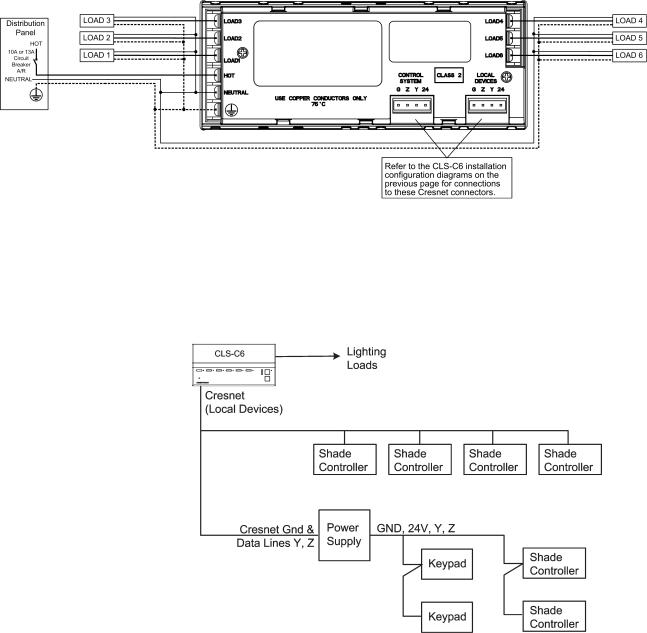
NOTE: The power usage requirements on the local devices network is different from that described above. The CLS-C6 provides 24VDC power for up to four keypads and/or shade controllers on the local devices network. An additional power supply is required to support more than four devices. Also, each C2N-SDC-DC shade controller requires its own additional power supply.
Operations Guide - DOC. 6347B |
iLux™ Lighting System: CLS/CLSI-C6 & CLS/CLSI-C6M • 9 |

iLux™ Lighting System |
Crestron CLS/CLSI-C6 & CLS/CLSI-C6M |
CLS-C6 Installation Configurations |
|
* Refer to “ Appendix A: Supported Devices” on page 40 for details on devices supported by the CLS-C6.
|
10 |
• iLux™ Lighting System: CLS/CLSI-C6 & CLS/CLSI-C6M |
Operations Guide - DOC. 6347B |
Crestron CLS/CLSI-C6 & CLS/CLSI-C6M |
iLux™ Lighting System |
Hardware Hookup
Refer to the following diagram for connection of the AC wiring. Connect each load wire to the corresponding LOAD terminals on the unit, connect the power line hot wire from the circuit breaker to the HOT terminal on the unit, connect all neutral wires to the NEUTRAL terminal on the unit, and connect all ground wires to the  (ground) terminal on the unit. For details, refer to the iLux Lighting System Installation Guide, Doc. 6394 for CLS-C6/C6M units, and Doc. 6413, for CLSIC6/C6M units.
Adding External Power Supplies
Additional power supplies are required to support more than four keypads or shade controllers on the local devices network. Also, each C2N-SDC-DC shade controller requires its own additional power supply. The following diagram illustrates a scenario where an external power supply is required to add keypads and shade controllers to a network that already contains four shade controllers. The actual quantity of external power supplies required depends on your system configuration.
Operations Guide - DOC. 6347B |
iLux™ Lighting System: CLS/CLSI-C6 & CLS/CLSI-C6M • 11 |

iLux™ Lighting System |
Crestron CLS/CLSI-C6 & CLS/CLSI-C6M |
Configuring the CLS-C6
The overall configuration of the CLS-C6 can be accomplished in two ways: using the front panel controls, or using the supplied iLux™ Designer application software, which can be downloaded from the Crestron website.
Configuring via the front panel controls is not as extensive as what can be done using the iLux Designer, but permits basic functional setup without having to use a PC.
In addition, some aspects of the CLS-C6’s operation can be modified only via certain Crestron Toolbox console commands. (Refer to “Console Command Settings” on page 23 for details. Refer also to “Appendix B: Console Commands” on page 41 for details on all applicable console commands.)
NOTE: Toolbox does not distinguish between the CLS-C6 and CLSI-C6 devices.
All report as CLS units.
Configuring With Front Panel Controls
You can make temporary changes to accommodate a particular circumstance, or change scene presets and replace the originals, as described below. To make more extensive changes in the configuration of the CLS-C6 without using the iLux Designer software, use the Setup Mode, as described beginning on page 13.
Temporary Changes/Adjustments
Temporary changes/adjustments to the lighting levels or shade presets can be accomplished as discussed in “Lights Mode” on page 34 and “Shades Mode” on page 35.
Changing Scene Presets
The CLS-C6 scene settings can be modified via the front panel controls without having to use a PC. Changes to the lighting load levels and shade presets for one or more scenes can be accomplished as follows:
NOTE: The iLux Designer or SIMPL programs can lock a scene to prevent it from being changed using the front panel controls. If the selected scene is “locked” in the configuration, when you try to make any adjustment, “Er” will display for three seconds, and the scene will remain in its existing state.
1.In Standard mode, press the function button of the scene you wish to modify and hold it for five seconds. (Make sure you press the center of the button so both sides make contact.)
2.The two-digit display will first count down as the lighting loads fade to their preset levels for that scene; it will then begin flashing between Sc. and the scene number; the Lights LED will be lit, and the Save and Cancel LEDs will flash.
3.Use the six function buttons to adjust the levels of the lighting loads for that scene. Press the left side of the buttons to lower the lighting loads; press the right side of the buttons to raise the lighting loads.
|
12 |
• iLux™ Lighting System: CLS/CLSI-C6 & CLS/CLSI-C6M |
Operations Guide - DOC. 6347B |
Crestron CLS/CLSI-C6 & CLS/CLSI-C6M |
iLux™ Lighting System |
4.If you would like a certain lighting load to be unaffected by that scene recall, press and hold the center of the button (so both sides make contact) for three seconds. The top two and the bottom two LEDs of the associated bargraph will be lit (and the display will show - -) to indicate that the level of the lighting load will not change when that scene is recalled.
5.To change the shade presets for that scene press the Shades button; the Shades LED will be lit.
6.Use the six function buttons to adjust the levels of the shade groups for that scene. Press the right side to raise the shades; press the left side to lower them. While the shades are moving, press any part of the button to stop. Note that for shades that are not “presettable,” only full open or full closed positions can be recalled as part of a scene.
7.If you would like a certain shade group to be unaffected by that scene recall, press and hold the center of the button (so both side make contact) for three seconds. The top two and the bottom two LEDs of the associated bargraph will be lit (and the display will show - - ) to indicate that the level of that shade group will not change when that scene is recalled.
8.To adjust the fade time, press the ^ and v buttons. When going up, the value will go from 0 seconds to 59 seconds, and then 1 minute to 99 minutes. When going down, the value will go from 99 minutes to 1 minute, and then 59 seconds to 0 seconds. The Min and Sec LEDs light as appropriate. Adjustment to fade time can be made when either Lights mode or Shades mode is active.
9.When all the lighting loads are at the desired level and shades are at the desired position, press Save to save these settings as the new preset for that scene. If you make a mistake while changing a setting, press Cancel to discard changes and return to Standard mode before pressing Save.
10.Repeat the above procedures for all scenes that require changes.
Setup Mode
The Setup mode is used to change internal settings on the CLS-C6, including the scene presets as discussed in the previous paragraph.
•To enter Setup mode, press and hold the Save and Cancel buttons for five seconds. The Cancel button LED will blink, and the first setup option (Sc) will be displayed, to indicate that the unit is now in Setup mode.
Note that while scrolling through the list of setup options, before an option is “locked”, the Save button is not functional and its LED is off. However, the Cancel button LED will blink - since the button can be pressed to return the unit to Standard mode.
•If the unit is connected to a Cresnet control system and you are in the process of adjusting scene settings, you cannot enter Setup mode. If you try, the two-digit display will indicate “Er” (error).
•When the unit is in Setup mode, the two-digit display uses a two-character mnemonic to indicate which specific aspect of the CLS-C6 you are changing. As these are being adjusted, the display may indicate values. The following is a list of the different Setup modes, and the corresponding mnemonic codes.
Operations Guide - DOC. 6347B |
iLux™ Lighting System: CLS/CLSI-C6 & CLS/CLSI-C6M • 13 |
iLux™ Lighting System |
Crestron CLS/CLSI-C6 & CLS/CLSI-C6M |
||
|
Setup Mode Mnemonics |
||
|
|
|
|
|
TWO-DIGIT |
DESCRIPTION |
|
|
DISPLAY |
|
|
|
Sc |
|
Scene Programming |
|
Ld |
|
Setup lighting load Load types |
|
LE |
|
Setup lighting load Low-End limits |
|
HE |
|
Setup lighting load High-End limits |
|
bF |
|
button Functions (i.e. recall scene, toggle scene, shades control, etc.) |
|
ud |
|
Set function of up/down button |
|
oc |
|
Setup occupancy Sensing |
|
Ad |
|
Run Auto-discovery |
|
AS |
|
Assign Shade groups |
|
|
|
|
|
id |
|
Set the Cresnet id of this unit |
|
Fd |
|
Restore Factory default |
|
Er |
|
Error |
•Press the ^ or v buttons to scroll through this list of available setup options. Once the desired setup option appears in the display, use the various buttons on the CLS-C6 to make adjustments, as described on the following pages.
•Once any adjustment is made, Setup mode is now “locked” into that particular option (this is indicated by lighting the period at the end of the mnemonic). Once locked in an option, the ^ and v buttons will no longer scroll through the options; you must exit setup before you can choose another option.
When the adjustments are complete, press Save to store the changes permanently, and exit Setup mode, or press Cancel to exit Setup mode without saving the changes. The unit reverts to Standard mode.
Scene Programming (Sc)
This setup option allows the user to adjust the scene parameters. This is another way to accomplish scene changes as discussed in “Changing Scene Presets” on page 12. This method also allows you to change the settings for scenes greater than scene 6.
Scenes can be turned off in addition to being recalled. When a scene is turned off, only the lighting loads are turned off. If the scene contains any shades, they are not affected. The fade time for turning the scene lights off is the same as for recalling the scene. Therefore, no additional parameters need to be set to define the off behavior.
Select the scene to be changed using the Up/Down button. As you cycle through the list of scenes, the lights and shades will not change, and the bargraphs will be off.
Set the lighting loads and shade positions for the scenes as discussed in “Changing Scene Presets” on page 12. As you set the scenes, note the following:
•When a lighting load reaches the HE (high end) limit, the lights will stop. The two-digit display will continue to rise. If lights reach the LE (low end) limit, the two-digit display will continue to go down, but lights will stay at the LE limit until they reach Off—at which point they will turn off. If you save the scene setting while the display is at a level below the LE limit, or above the HE limit, the displayed value will be saved, but the light level will be limited to the programmed limits.
•If a lighting load is defined as an “unused” load type, the bargraph for that lighting load will have all LEDs off. If you try to adjust that lighting load, the two-digit display will show “Er”.
|
14 |
• iLux™ Lighting System: CLS/CLSI-C6 & CLS/CLSI-C6M |
Operations Guide - DOC. 6347B |
Loading...