


 Loading...
Crestron CHV-TSTAT & CHV-THSTAT
Thermostats
Operations and Installation Guide

This document was prepared and written by the Technical Documentation department at:
Crestron Electronics, Inc.
15 Volvo Drive
Rockleigh, NJ 07647
1-888-CRESTRON
All brand names, product names and trademarks are the property of their respective owners. ©2003 Crestron Electronics, Inc.
Crestron CHV-TSTAT and CHV-THSTAT |
Thermostats |
Contents |
|
Quick Installation Reference ..................................................................................................... |
ii |
Thermostats: CHV-TSTAT and CHV-THSTAT |
1 |
Introduction ............................................................................................................................... |
1 |
Functions and Features ................................................................................................ |
1 |
Specifications .............................................................................................................. |
3 |
Physical Description.................................................................................................... |
4 |
Industry Compliance ................................................................................................... |
6 |
Setup .......................................................................................................................................... |
7 |
Network Wiring........................................................................................................... |
7 |
Identity Code ............................................................................................................... |
7 |
System Connections .................................................................................................... |
8 |
Wiring Diagrams ....................................................................................................................... |
9 |
Separately Powered (by an independent transformer)................................................. |
9 |
Three-Wire Heating System Connections ................................................................. |
10 |
Five-Wire Heating/Cooling System Connections...................................................... |
11 |
Heat Pump Connections (Single & Two-Stage)........................................................ |
12 |
Installation ............................................................................................................................... |
14 |
Thermostat Setup and Operation ............................................................................................. |
16 |
Setup Procedure......................................................................................................... |
16 |
Operating the Thermostat .......................................................................................... |
21 |
Programming Software............................................................................................................ |
24 |
Programming with Crestron D3 Pro.......................................................................... |
25 |
Programming with SIMPL Windows ........................................................................ |
25 |
Viewport ID String.................................................................................................... |
36 |
Problem Solving ...................................................................................................................... |
37 |
Troubleshooting......................................................................................................... |
37 |
Further Inquiries ........................................................................................................ |
38 |
Firmware Upgrades ................................................................................................... |
38 |
Future Updates .......................................................................................................... |
38 |
Appendix A: Glossary ............................................................................................................. |
39 |
Appendix B: About Heat Pumps.............................................................................................. |
40 |
Return and Warranty Policies .................................................................................................. |
41 |
Merchandise Returns / Repair Service ...................................................................... |
41 |
CRESTRON Limited Warranty................................................................................. |
41 |
Operations and Installation Guide – DOC. 8163A |
Contents • i |

Thermostats |
Crestron CHV-TSTAT and CHV-THSTAT |
Quick Installation Reference
1.Select a suitable location and run the connecting wires from the heating/cooling system and the Cresnet system. Refer to page 5 for a description of the thermostat connectors.
Refer to page 7 for Network wiring details. Use the appropriate wiring diagram:
•Heating or Cooling System Powered (Refer to page 9).
•Separately Powered (Refer to page 9).
•Three Wire Heat Only with Fan (Refer to page 10).
•Five Wire Heat/Cool Systems (Refer to page 11)
•Single Stage and Two Stage Heat Pump (Refer to page 12).
2.Separate the thermostat from the backplate to expose the connections and mounting holes.
3.Mount the thermostat backplate (60 inches above the finished floor) directly to the wall with wall anchors (not provided) and screws (not provided) or to a single-gang box (not provided) mounted horizontally, and connect the wiring. Refer to page 14 for detailed mounting instructions and page 8 for detailed connector information. If using a five-sided box, fill with insulation material to minimize wall air ingress.
4.Install the thermostat on the backplate (Refer to page 14).
5.Setup the thermostat (Refer to page 16).
6.Configure the thermostat (Refer to Operating the Thermostat on page 21).
ii • Thermostats: CHV-TSTAT and CHV-THSTAT |
Operations and Installation Guide – DOC. 8163A |

Crestron CHV-TSTAT and CHV-THSTAT |
Thermostats |
Thermostats: CHV-TSTAT and
CHV-THSTAT
Introduction
Functions and Features
The CHV-TSTAT and CHV-THSTAT series are wall-mounted universal thermostats that can be part of a Crestron Home® total control system. The thermostats are capable of controlling one or two-stage heating and cooling systems. Each thermostat is available in three colors: almond, black and white. The suffix ‘A’, ‘B’, and ‘W’, respectively denotes color, e.g., CHV-TSTATB is a black unit. For simplicity within this guide, color suffix is omitted and the designations CHVTSTAT and CHV-THSTAT are used except where noted.
Functional Summary
•User adjustable temperature and/or humidity control of one and two-stage heating and cooling systems
•128 x 64 transflective 2.75 inch (6.99 cm) LCD display
•Fahrenheit or Celsius indication
•Four-front panel buttons for setup, configuring and temperature/humidity adjustments
•Back light (with each button press) for night viewing
•Supports up to two remote temperature and/or temperature/humidity sensors. Future firmware releases will support up to four remote sensors per thermostat
•Operates as a stand-alone device or in a Cresnet® system
•Extended functionality as a Cresnet device for lighting control, alarms, etc.
The CHV-TSTAT provides temperature control, while the CHV-THSTAT provides temperature and humidity control. Temperature and humidity information is provided through a transflective LCD display. Four front panel buttons and the LCD display provide temperature and/or humidity indication and control, current system status, and current fan mode. The LCD also provides status indicators denoting when heat, cool, humidity or fan outputs are energized; a message indicator, so users know when a message is waiting to be read; a net indicator to denote when the network is active and a hold indicator that identifies when the thermostat is overriding the Cresnet temperature set point commands.
Operations and Installation Guide – DOC. 8163A |
Thermostats: CHV-TSTAT and CHV-THSTAT • 1 |

Thermostats |
Crestron CHV-TSTAT and CHV-THSTAT |
Remote Sensors
The current firmware release supports the addition of two optional remote sensors: temperature only (CHV-RTS) and/or temperature/humidity (CHV-RTHS), for both thermostats.
Outdoor conditions can be imported from the optional external sensors CHV-RTS or CHV-RTHS, temperature and temperature/humidity respectively.
Subsequent firmware releases will support the addition of up to four optional remote sensors, in any combination, for each thermostat. For additional information about the sensors, refer to the latest revision of the CHV-RTS & CHV-RTHS Installation Guide (Doc. 8189), which is available from the Crestron website (www.crestron.com).
NOTE: The CHV-TSTAT and CHV-THSTAT allow the user to set a temperature that the heating and/or cooling system maintains. This is called the “Set Point”. Refer to “Operating the Thermostat” on page 21 for more information.
NOTE: Crestron sensors are suitable for mounting in dry or damp locations as defined by the National Electrical Code.
NOTE: Installers should have a strong working knowledge of HVAC systems.
Heating and Cooling Systems
The CHV-TSTAT can control the following heating and cooling systems:
•One stage heat
•One stage heat, one stage cool
•One stage heat, one stage cool: heat pump with auxiliary heat
•Two stage heat
•Two stage heat, one stage cool
•One stage heat, two stage cool
•Two stage heat, two stage cool
•Two stage heat, two stage cool: heat pump with auxiliary heat
NOTE: Two Stage Heating – Unlike traditional furnaces that turn on and run at full capacity with each demand for heating, two-stage heat operates like two separate furnaces to maintain more consistent comfort in your home. The unit starts out running in its first stage, and operates at a fraction of its heating capacity. This reduced capacity is sufficient to warm your home on mild winter days. But when the temperature outside goes very low, the furnace adjusts to full capacity (second stage) to meet the demand for heat within the home.
Two Stage Cooling – In warm weather, the first stage of the cooling equipment operates at a fraction of the total cooling capacity. On very hot days, the second stage of the cooling equipment energizes, and the cooling system operates at full capacity.
2 • Thermostats: CHV-TSTAT and CHV-THSTAT |
Operations and Installation Guide – DOC. 8163A |
Crestron CHV-TSTAT and CHV-THSTAT |
Thermostats |
Specifications
The following table provides a summary of specifications for the CHV-TSTAT and
CHV-THSTAT.
CHV-TSTAT and CHV-THSTAT Specifications
SPECIFICATION |
DETAILS |
|
|
Power Requirements
Crestron power factor
Default Network ID
Control System Update Files1,2,3 2-Series Control System CEN/CN-TVAV CNMSX-AV/PRO CNRACKX/-DP
ST-CP
LCD Display
Screen Viewing Angles
Humidity Range
Auto Setpoint Range (union of heat and cool setpoint ranges)
Heat Only Setpoint Range
Cool Only Setpoint Range
Temperature Measurement Range
Firmware Update Files4
CHV-TSTAT/CHV-THSTAT
Update Files
Dimensions and Weight
2 Watts (24 VAC @ 83mA) Heating or Cooling System Supplied
<1Watt (required for Cresnet communication only)
2A
Version C2-2004.CUZ or later Version 5.10.13V.UPZ or later Version 5.07.05X.UPZ or later Version 5.07.06W.UPZ or later Version 4.00.49S.UPZ or later
128 x 64 Transflective 2.75 in (6.99 cm)
Y Dir. (X=0º): +50º (from top) –50º (from bottom)
X Dir. (X=10º): +50º (from right) –50º (from left)
0 – 100%
38 –-99°F (3 – 37°C)
38 –- 89°F (3 – 32°C)
59 –- 99°F (15 – 37°C)
0 – 110° (-18 – 43°C)
CHVTSTAT.xx.UPG or later CHVTHSTAT.x.x.UPG or later Height: 3.75 in (9.50 cm) Width: 5.00 in (12.70 cm) Depth: 1.04 in (2.63 cm) Weight: 5.80 oz (165 g)
1.The latest versions can be obtained from the Downloads | Software Updates section of the Crestron website (www.crestron.com). Refer to NOTE after last footnote.
2.Crestron 2-Series control systems include the AV2, CP2, CP2E, MP2, MP2E, PAC2, PRO2, and RACK2.
3.CNX update files are required for either CNMSX-AV/Pro or CNRACKX/-DP. Filenames for CNX update files have a UPZ extension and ST-CP files are in one EXE or zipped UPZ file. To avoid program problems, make certain you are using the update file with the correct suffix letter (e.g., S, V, W, X).
4.Filenames for CHV update files have a UPG extension and are in one zipped UPG file. The ‘x’ in the file name refers to the version number.
NOTE: Crestron software and any files on the website are for Authorized Crestron dealers only. New users may be required to register to obtain access to certain areas of the site (including the FTP site).
Operations and Installation Guide – DOC. 8163A |
Thermostats: CHV-TSTAT and CHV-THSTAT • 3 |
Thermostats |
Crestron CHV-TSTAT and CHV-THSTAT |
Physical Description
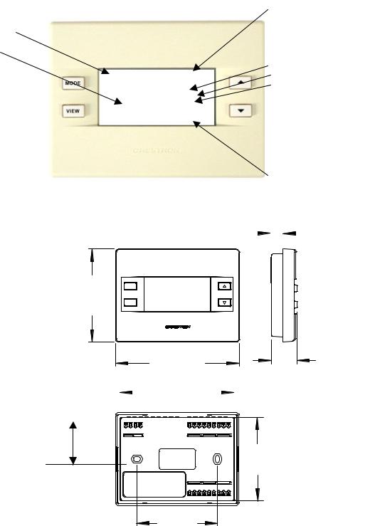
Current Temperature
Current Humidity
Refer to the illustrations below and on next page. The CHV-TSTAT and CHVTHSTAT are enclosed in a plastic enclosure with four buttons and an LCD display on the front. The back of the unit has ventilation slots, and holes for mounting the unit and wiring. The ventilation slots must be unobstructed for airflow to the unit.
Physical View of CHV-TSTAT and CHV-THSTAT
|
|
|
|
|
|
Current Set Point |
|||
|
|
|
|
|
|
(indicates desired |
|||
|
|
|
|
|
|
temperature, or |
|||
|
|
|
|
|
|
temperature range in |
|||
|
|
|
|
|
|
auto mode) |
|||
|
|
|
|
|
|
Current Activity |
|||
|
66 |
o |
o |
|
|
Current Function |
|||
|
F |
68 F |
|
|
System Information |
||||
|
|
HEATING |
- |
|
ON LINE (Cresnet |
||||
|
% |
HEAT ONLY |
|
||||||
|
43 |
ON LINE |
|
|
|
|
on) |
||
|
|
H1 H2 AX |
- |
|
HOLD (Cresnet |
||||
|
|
|
|
|
|
|
off) |
||
|
|
|
|
|
|
|
|
||
|
|
|
|
|
|
|
|
||
|
|
|
|
- |
|
NET FAULT (Net |
|||
|
|
|
|
|
|
|
|
down) |
|
|
|
|
|
- |
|
VIEW MSG (view |
|||
|
|
|
|
|
|
|
|
message) |
|
|
|
|
|
|
|
Internal Relay Status |
|||
|
|
|
|
|
0.47 in |
|
|
||
Front and Side Views |
|
|
|
(1.18 cm) |
|
|
|||
|
|
|
|
|
|
|
|
|
|
|
|
|
|
|
|
|
|
|
|
|
|
|
|
|
|
|
|
|
|
3.75 in |
MODE |
|
|
(9.50 cm) |
VIEW |
|
|
|
|
5.00 in |
|
|
|||
|
|
|
|
(12.70 cm) |
|
1.04 in |
|||
|
|
|
|
4.630 in |
|
|
(2.63 cm) |
||
|
|
|
|
|
|
||||
|
|
|
|
|
|
|
|||
Rear View |
|
|
(11.76 cm) |
|
|
||||
|
|
|
|
|
|
|
|
||
|
|
|
|
|
|
|
|
|
|
|
|
|
|
|
|
|
|
|
|
1.75 in
(4.44 cm)
3.38 in
(8.59 cm)
3.27 in |
(8.29 cm) |
4 • Thermostats: CHV-TSTAT and CHV-THSTAT |
Operations and Installation Guide – DOC. 8163A |
Crestron CHV-TSTAT and CHV-THSTAT |
Thermostats |
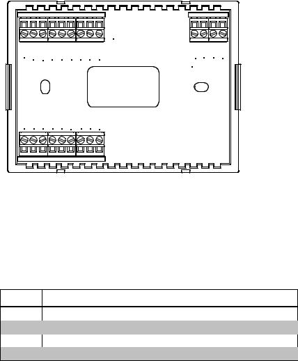
Connection View (Backplate, view from the front with cover removed)
|
|
|
|
|
|
TOP |
HUM RHU |
RSR |
RSR |
RS1 |
RS2 24(C) |
24(R) |
24V Y Z G |
|
|
|
|
|
|
NETWORK |
RH RC G |
Y/Y1 |
Y2 |
O |
B W/W1 |
W2 |
|
Ports
The CHV-TSTAT and CHV-THSTAT have four types of connections on the inside back plate (refer to graphic above).
NETWORK (Optional) – provides communication to the control system and Cresnet power to the CHV-TSTAT and CHV-THSTAT. If making network connections to Cresnet peripherals, refer to “Network Wiring” on page 7.
CRESNET CONNECTIONS (optional)
PIN DESCRIPTION
24 +24VDC
YCresnet Data
ZCresnet Data
GGround
REMOTE SENSING CONNECTIONS (optional)
PIN |
DESCRIPTION |
|
|
RSR |
Remote Sensor Returns – Common sensor terminal |
RS1 |
Remote Sensor terminal – Connect the sensor from RS1 to RSR |
RS2 |
Remote Sensor terminal – Connect the sensor from RS2 to RSR |
POWER CONNECTIONS (Required) |
|
|
|
PIN |
DESCRIPTION (refer to System Connections on page 8) |
|
|
24 (C) |
24 VAC common terminal supplies remote 24 VAC power to |
|
thermostat. |
24 (R) |
24 VAC reference terminal. Can be connected to RH or RC by |
|
P4 jumper setting, or tied directly to power source (refer to |
|
System Connections on page 8) |
Operations and Installation Guide – DOC. 8163A |
Thermostats: CHV-TSTAT and CHV-THSTAT • 5 |
Thermostats |
Crestron CHV-TSTAT and CHV-THSTAT |
CONTROL CONNECTIONS (System Dependent)
PIN |
DESCRIPTION |
|
|
HUM |
Energized to RHU during humidity call |
|
|
RHU |
Reference for humidifier |
RH |
Reference Heat, used for calls to heating system |
|
|
RC |
Reference Cool, used for calls to cooling system |
G |
Fan, energized to RC during call for fan |
Y/Y1 |
Compressor (stage one), energized to RC when |
|
compressor (or first stage) is run |
Y2 |
Compressor (stage two), energized to RC on two-stage |
|
systems on call for second stage |
O |
Changeover control, energized to RC during cooling modes |
B |
Energized to RC during non-cooling modes |
W/W1 |
Heat (single stage)/heat (stage one) energized to RH |
|
during a call for heat in heat/cool systems or aux heat in |
|
heat pump systems |
W2 |
Heat (stage two), energized to RH during a call for second |
|
stage heat in heat/cool systems |
Buttons
There are four buttons used to setup and adjust the thermostat.
MODE MODE – Access to the user controls (System Mode, Fan Mode,
Humidifier, Crestron System, and Global Update)
VIEW |
VIEW – Access to Humidity reading, Outdoor Temperature reading, and |
|
|
|
System Messages. |
NOTE: When MODE and VIEW are pressed together and held for five seconds, the thermostat enters the system setup mode (refer to “Thermostat Setup” on page 16).
T
UP ▲ – Selects user modes and increments selection in setup modes
TDOWN ▼ – Selects user modes and decrements selection in setup modes
Industry Compliance
As of the date of manufacture, this unit has been tested and found to comply with specifications for CE marking and standards per EMC and Radio Communications Compliance Labeling (N11785).
NOTE: This device complies with part 15 of the FCC rules. Operation is subject to the following two conditions: (1) this device may not cause harmful interference, and
(2) this device must accept any interference received, including interference that may cause undesired operation.
6 • Thermostats: CHV-TSTAT and CHV-THSTAT |
Operations and Installation Guide – DOC. 8163A |
Crestron CHV-TSTAT and CHV-THSTAT |
Thermostats |
Setup
Network Wiring
NOTE: When installing network wiring, refer to the latest revision of the wiring diagram(s) appropriate for your specific system configuration, available from the Downloads | Product Manuals | Wiring Diagrams section of the Crestron website (www.crestron.com).
When calculating the wire gauge for a particular Cresnet run, the length of the run and the power factor of each network unit to be connected must be taken into consideration. If Cresnet units are to be daisy-chained on the run, the power factor of each unit to be daisy-chained must be added together to determine the power factor of the entire chain. If the unit is a home-run from a Crestron system power supply network port, the power factor of that unit is the power factor of the entire run. The length of the run in feet and the power factor of the run should be used in the following resistance equation to calculate the value on the right side of the equation.
Resistance Equation
40,000 |
|
Where: R = Resistance (refer to table below). |
|
R < L x PF |
L = Length of run (or chain) in feet. |
PF = Power factor of entire run (or chain). |
The required wire gauge should be chosen such that the resistance value is less than the value calculated in the resistance equation. Refer to the table below.
Wire Gauge Values
RESISTANCE |
WIRE GAUGE |
|
|
4 |
16 |
|
|
6 |
18 |
10 |
20 |
15 |
22 |
13 |
Doubled CAT 5 |
8.7 |
Tripled CAT 5 |
|
|
NOTE: All Cresnet wiring must consist of two twisted-pairs. One twisted pair is the +24V conductor and the GND conductor and the other twisted pair is the Y conductor and the Z conductor.
NOTE: For larger networks (i.e., greater than 28 network devices), it may be necessary to add a Cresnet Hub/Repeater to maintain signal quality throughout the network. Also, for networks with lengthy cable runs or varying types of network devices, it may be desirable to add a hub/repeater after only 20 network devices.
Identity Code
Every equipment and user interface within the network requires a unique Cresnet identity code (NET ID). These codes are assigned a two-digit hexadecimal number from 03 to FE. The NET ID of the unit must match the NET ID specified in the SIMPL Windows or D3 Pro program. Refer to “Device Options” on page 18 for a description of assigning the NET ID to the thermostat and “Setting the Net ID in Device Settings” on page 26 for an example of the SIMPL Windows procedure.
Operations and Installation Guide – DOC. 8163A |
Thermostats: CHV-TSTAT and CHV-THSTAT • 7 |
Thermostats |
Crestron CHV-TSTAT and CHV-THSTAT |
System Connections
Backplate - view from the front with the cover removed
|
|
|
|
|
|
|
|
HUM - Energized to RHU during humidity call |
|
|
|
|
|
|
|
|
RHU - Reference for humidifier |
|
|
|
|
|
|
|
|
RSR - Remote Sensor Returns - Common sensor terminal |
|
|
|
|
|
|
|
|
RS1 - Remote Sensor terminal - Connect the sensor from RS1 to RSR |
|
|
|
|
|
|
|
|
RS2 - Remote Sensor terminal - Connect the sensor from RS2 to RSR |
|
|
|
|
|
|
|
|
24(C) - 24 VAC common terminal supplies remote 24 VAC power |
|
|
|
|
|
|
|
|
to thermostat |
|
|
|
|
|
|
|
|
24(R) - 24 VAC reference terminal. Can be connected to RH or RC |
|
|
|
|
|
|
|
|
by P4 jumper setting, or tied directly to power source |
|
|
|
|
|
|
|
|
Network Connection |
|
|
|
|
|
|
24(C) |
TOP |
for Crestron |
HUM |
RHU |
RSR |
RSR |
RS1 |
RS2 |
24(R) |
Installer Only |
|
24V Y Z G |
||||||||
|
|
|
|
|
|
|
|
NETWORK |
RH |
R C |
G Y/Y1 Y2 O B W/W1 W 2 |
|
|
Backplate |
|
|
W2 - Heat (stage two), energized to RH during a call for |
|
|
second stage heat in heat/cool systems |
|
|
W/W1 - Heat (single stage)/heat (stage one) energized to RH |
|
|
during a call for heat in heat/cool systems or aux heat in |
|
|
heat pump systems |
|
|
B - Energized to RC during non-cooling modes |
|
|
O - Changeover control, energized to RC during cooling modes |
|
|
Y2 - Compressor (stage two), energized to RC on two-stage |
|
|
systems on call for second stage |
|
|
Y/Y1 - Compressor (stage one), energized to RC when |
|
|
compressor (or first stage) is run |
|
|
G - Fan, energized to RC during call for fan |
|
|
RC - Reference Cool, used for calls to cooling system |
|
|
RH - Reference Heat, used for calls to heating system |
8 • Thermostats: CHV-TSTAT and CHV-THSTAT |
Operations and Installation Guide – DOC. 8163A |
Crestron CHV-TSTAT and CHV-THSTAT |
Thermostats |
Wiring Diagrams
The wiring diagrams that follow show connections for the CHV-TSTAT and CHV-
THSTAT.
CAUTION: The P4 Jumper Position on the Circuit Board depends on the power method chosen, and is critical to proper operation. Improper P4 jumper position can cause equipment damage.
NOTE: Ensure that the power circuits are shut off at the source before connecting the thermostat. Provide disconnect means and overload protection as required for the power supply.
NOTE: Ensure that the transformer has sufficient power for all the thermostats in the system, or use multiple transformers. Refer to the power requirements in “Specifications” on page 3.
The following diagrams are examples of connections for heat, heat/cool and onestage and two-stage heat pump systems.
NOTE: Use either connector O or B as required, for changeover control.
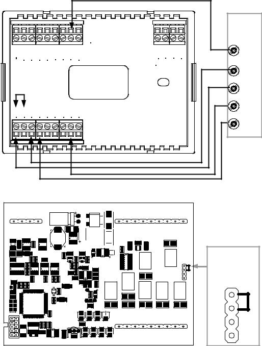
Separately Powered (by an independent transformer)
Backplate Connection and Circuit Board Jumper Position
|
|
|
|
|
Transformer |
|
|
|
|
|
|
|
|
24(C) |
|
|
|
|
|
|
|
|
24 VAC |
120 VAC |
|
|
|
|
|
|
|
24(R) |
|
|
|
|
|
|
|
|
|
|
Jumper on P4 between pins 2 and 3 |
|
|
|
|
|
|
|
|
CRESTRON ELECTRONICS |
|
|
|
|
|
|
|
|
P 6 |
|
|
|
|
|
|
|
|
P3 |
|
|
|
|
|
|
TOP |
|
|
|
|
HUM RHU RSR |
RSR |
RS1 |
RS2 24(C) |
24(R) |
24V Y |
Z G |
|
|
|
|
|
|
|
NETWORK |
|
|
|
|
|
|
|
|
|
P4 |
|
|
|
|
|
|
|
|
1 |
P4P4 |
|
|
|
|
|
|
|
2 |
|
|
|
|
|
|
|
|
3 |
|
|
|
|
|
|
|
|
4 |
|
RH |
RC G Y/Y1 |
Y2 |
O |
B W/W1 |
W2 |
|
2 |
1 |
|
2 |
|||||||
|
|
|
|
|
|
|
||
|
|
|
|
|
|
|
3 |
|
|
|
|
|
|
|
|
P5 |
3 |
|
|
|
|
|
|
|
P1 |
4 |
Backplate |
Thermostat circuit board |
NOTE: The P4 jumper position is critical to proper operation and depends on the method used to power the thermostat.
Operations and Installation Guide – DOC. 8163A |
Thermostats: CHV-TSTAT and CHV-THSTAT • 9 |

Thermostats |
Crestron CHV-TSTAT and CHV-THSTAT |
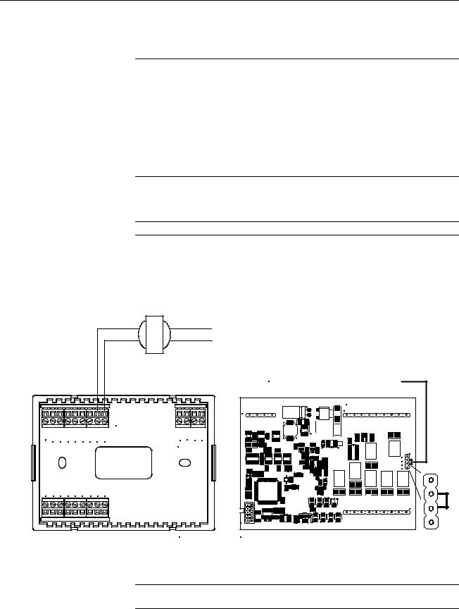
Three-Wire Heating System Connections |
|||||||
Backplate |
|
|
|
|
|
|
|
|
|
|
|
|
|
Integrated |
|
|
|
|
|
|
|
Control |
|
|
|
|
|
|
TOP |
Unit |
|
|
|
|
|
|
C |
||
HUM RHU RSR |
RSR |
RS1 |
RS2 24(C) |
24(R) |
24V Y |
||
Z G |
|||||||
|
|
|
|
|
NETWORK |
||
|
|
|
|
|
|
R |
|
R H RC G Y/Y1 |
Y2 |
|
B W/W1 |
W2 |
|
W |
|
O |
|
|
|||||
Thermostat Circuit Board
CRESTRON ELECTRONICS
P3 |
P6 |
P4 |
1 |
2 |
3 |
4 |
P5
P1 |
Jumper on P4 between pins 1 and 2
P4
1
2
10 • Thermostats: CHV-TSTAT and CHV-THSTAT |
Operations and Installation Guide – DOC. 8163A |
Crestron CHV-TSTAT and CHV-THSTAT |
Thermostats |
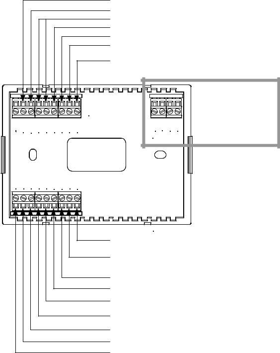
Five-Wire Heating/Cooling System Connections
Backplate |
|
|
|
|
|
|
|
|
|
|
|
|
|
|
|
Integrated |
|
|
|
|
|
|
|
|
Control |
|
|
|
|
|
TOP |
|
|
Unit |
|
|
|
|
|
|
|
C |
||
HUM RHU RSR RSR |
RS1 |
RS2 24(C) |
24(R) |
24V |
Y |
Z G |
||
|
||||||||
Jumper |
|
|
|
NETWORK |
G |
|||
|
|
|
|
|
|
|||
From RH |
|
|
|
|
|
R |
||
to RC |
|
|
|
|
|
|
||
R H RC G Y/Y1 Y2 |
O |
B W/W1 |
W2 |
|
|
|
W |
|
|
|
|
|
|||||
|
|
|
|
|
|
|
Y |
|
Thermostat Circuit Board
CRESTRON ELECTRONICS
P3 |
P6 |
|
|
Jumper on P4 |
|
P4 |
between pins 1 |
|
2 |
and 2 |
|
1 |
|
|
3 |
P4 |
|
4 |
||
|
1 |
2 |
P5
P1 |
Operations and Installation Guide – DOC. 8163A |
Thermostats: CHV-TSTAT and CHV-THSTAT • 11 |
Loading...