


 Loading...
Crestron C2N-VEQ4
Cresnet 4-Channel Digital Volume Control
Operations Guide

This document was prepared and written by the Technical Documentation department at:
Crestron Electronics, Inc.
15 Volvo Drive
Rockleigh, NJ 07647
1-888-CRESTRON
All brand names, product names and trademarks are the property of their respective owners. ©2005 Crestron Electronics, Inc.
Crestron C2N-VEQ4 |
Cresnet 4-Channel Digital Volume Control |
Contents
Cresnet 4-Channel Digital Volume Control: C2N-VEQ4 |
1 |
Introduction ............................................................................................................................... |
1 |
Features and Functions................................................................................................ |
1 |
Specifications .............................................................................................................. |
3 |
Physical Description.................................................................................................... |
4 |
Industry Compliance ................................................................................................... |
7 |
Setup .......................................................................................................................................... |
7 |
Network Wiring........................................................................................................... |
7 |
Identity Code ............................................................................................................... |
8 |
Hardware Hookup ..................................................................................................... |
11 |
Programming Software............................................................................................................ |
13 |
Earliest Version Software Requirements for the PC ................................................. |
13 |
Programming with the Crestron SystemBuilder........................................................ |
13 |
Programming with SIMPL Windows........................................................................ |
14 |
Uploading and Upgrading ....................................................................................................... |
26 |
Communication Settings ........................................................................................... |
26 |
Uploading a SIMPL Windows Program ................................................................... |
28 |
Firmware Upgrade..................................................................................................... |
30 |
Problem Solving ...................................................................................................................... |
31 |
Troubleshooting ........................................................................................................ |
31 |
Further Inquiries........................................................................................................ |
32 |
Future Updates .......................................................................................................... |
32 |
Return and Warranty Policies.................................................................................................. |
33 |
Merchandise Returns / Repair Service ...................................................................... |
33 |
CRESTRON Limited Warranty ................................................................................ |
33 |
Operations Guide - DOC. 6135A |
Contents • i |

Crestron C2N-VEQ4 |
Cresnet 4-Channel Digital Volume Control |
Cresnet 4-Channel Digital Volume
Control: C2N-VEQ4
Introduction
Features and Functions
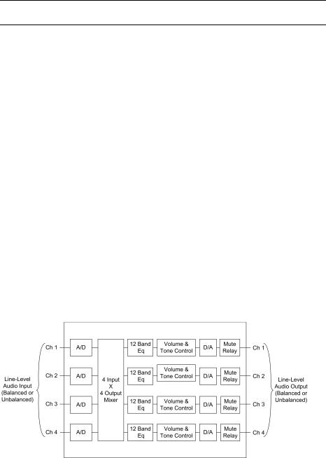
The Crestron® C2N-VEQ4 Cresnet® 4-Channel Digital Volume Control module is a digitally controlled 4-channel audio processor that incorporates volume, tone, mixer and equalization capabilities. Each channel has independent settings for volume, treble, bass, mute, and mixer controls plus a 12-band parametric equalizer. Volume/tone controls are compatible with both X-Generation and 2-Series control systems. Equalization and mixer controls are only accessible from 2-Series processors.
Refer to the simplified block diagram provided on the next page.
Functional Summary
•Four balanced/unbalanced audio I/O channels
•24-bit 96KHz A/D and D/A converters with dual DSPs provide improved audio quality
•Independent settings for volume, treble, bass, and mute per channel
•4 x 4 matrix mixer controls set the percentage of each input desired at each output (any input to any output)
•Five modes of audio equalization per channel
-a ten-band graphic equalizer and two-band parametric equalizer
-a five-band graphic equalizer and seven-band parametric equalizer
-a speech-optimized five-band graphic equalizer and seven-band parametric equalizer
-a three-band graphic equalizer and nine-band parametric equalizer
-a full twelve-band parametric equalizer
•Touch settable ID capable
Volume, bass, and treble ramp times, scaling, preset levels, and volume muting may be specified on a per-channel basis. All of these aspects are software controllable. Volume, bass, and treble control may be sent to more than one channel via software to support stereo applications.
Operations Guide - DOC. 6135A |
Cresnet 4-Channel Digital Volume Control: C2N-VEQ4 • 1 |
Cresnet 4-Channel Digital Volume Control |
Crestron C2N-VEQ4 |
Input and output connections are completely independent of each other. Therefore, it is possible to have a balanced input paired with an unbalanced output and vice-versa.
The treble and bass controls are independent from volume and are individually controlled for each channel. Each channel includes a muting relay with 100 dB attenuation. When the signal driving Mute1 goes high, the muting circuit is activated providing 100 dB attenuation from any preset volume level. Likewise, channels “2,” “3,”and “4” drive Mute2, Mute3, and Mute4, respectively. When the muting signal goes low, the muting circuit is deactivated and the volume and tone return to their original preset levels.
NOTE: MuteAll is an override. All channels are muted when this signal is high.
When it is low, the channels follow the state of Mute1, Mute2, Mute3 and Mute4.
Each of the four channels has a twelve-filter parametric equalizer that permits you to correct for acoustical distortions in the listening area or in the speakers themselves, and/or to establish preset values that enhance the sound conditions for favorite music or recording media.
Equalization controls are programmable using Crestron’s Digital Media Tools (DMT) software or SIMPL Windows (SIMPL). Refer to “Programming Software” on page 13 for details.
The 12 filters are identical in function. Each delivers up to 12 dB of boost or cut when using DMT software; from -36 dB to +24 dB in a SIMPL program. Each filter also has an adjustable bandwidth control (from 0.02 octaves to 2 octaves using DMT software; from 0.02 octaves to 3.5 octaves using SIMPL), and a center frequency control range (from 25 Hz to 19.9 kHz from DMT; from 5 Hz to 24 kHz using SIMPL). Use each filter anywhere in the audio spectrum, not just pre-selected ranges as typically found on graphic equalizers. In addition, you can select from among five filter types (low pass, high pass, peaking EQ (equalization)/notch, bass shelf, and treble shelf) or select no filter.
Each channel is equipped with protective relays that turn ON only after safe conditions are sustained by the electronic circuitry. This feature protects the output from “pops” caused by accidental power-down/up conditions to the C2N-VEQ4.
If the C2N-VEQ4 is under program control and the power is cycled to the C2N-VEQ4, it renews the volume, bass, and treble levels to the current program settings. The mute status (per channel and the mute-all) is also restored.
C2N-VEQ4 Simplified Block Diagram
2 • Cresnet 4-Channel Digital Volume Control: C2N-VEQ4 |
Operations Guide - DOC. 6135A |
Crestron C2N-VEQ4 |
Cresnet 4-Channel Digital Volume Control |
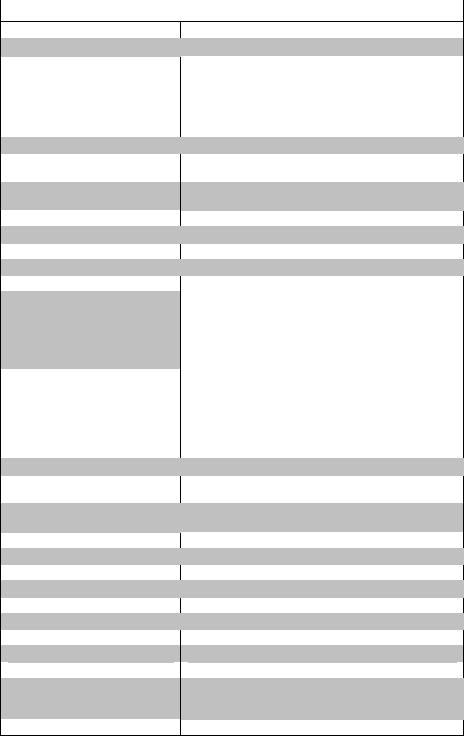
Specifications
The table after this paragraph provides a summary of specifications for the
C2N-VEQ4 module.
Specifications of the C2N-VEQ4
SPECIFICATION |
DETAILS |
Cresnet Power Usage
Default Net ID
Control System Update Files 1, 2, 3
2-Series Control System CNMSX-AV/PRO CNRACKX/-DP
ST-CP CEN/CN-TVAV
C2N-VEQ4 Firmware
Input Channels (labeled 1 – 4)
Output Channels (labeled 1 – 4)
Output Channel Volume
Input channel mixer controls
NET
Volume (per channel)
Mute (per channel)
Tone (per channel)
Parametric EQ Filter
Gain
Filter bandwidth
Filter center bandwidth
Filter types
Graphic EQ Filter Gain
Frequency response
Total harmonic distortion (THD) + Noise
S/N ratio
Crosstalk
Common mode rejection
Input level (max.)
Input impedance
Output level
Output impedance
Environmental temperature
Humidity
Dimensions
Weight
8.0 Watts (0.3 Amp @ 24 VDC)
12
Version 2.004.CUZ or later
Version 5.12.63X.UPZ or later
Version 5.12.63W.UPZ or later
Version 4.02.4S.UPZ or later
Version 5.12.63V.UPZ or later
C2N-VEQ4.1.35.upg
Two 5-pin mini-connectors: two channels plus ground per connector.
Two 5-pin mini-connectors: two channels plus ground per connector.
-80 dB to +20 dB
-80 dB to 0 dB
One – Cresnet® 4-wire interface (24, Y, Z, G)
-80dB to +20dB, 0.5dB control step [balanced I/O]
> -100dB
Bass 3dB @ 250 Hz |
|
Bass gain range |
±15dB |
Bass step size |
0.5Db |
Treble 3dB @ 6 kHz |
|
Treble gain range |
±15dB |
Treble step size |
0.5dB |
±12 dB, 0.1 dB steps (DMT); +24/-36 dB, 0.1 dB steps (SIMPL)
0.02 to 2.00 octaves (DMT); 0.02 to 3.50 (SIMPL) 25 Hz to 19.9 kHz (DMT); 5 Hz to 24 kHz (SIMPL)
Low pass, high pass, EQ filter (peaking/notching), bass shelf, and treble shelf
±12 dB, 0.1 dB steps
±0.1dB 20-22kHz ±0.5dB 10Hz-30kHz
<0.008% @1kHz
>97dB balanced, >95dB unbal., 20Hz-22kHz A-weighted
>-90dB 20Hz-22kHz
>90dB 20Hz-22kHz
4Vrms balanced, 2Vrms single-ended
10K ohms balanced, 5K ohms single-ended
4Vrms balanced, 2Vrms single-ended
200 ohms balanced, 100 ohms single-ended
32° to 122°F (0° to 50°C)
10% to 90% RH (non-condensing)
Height: 1.80 in (4.57 cm)
Width: 7.07 in (17.96 cm)
Depth: 6.32 in (16.05 cm)
1.86 lb (0.837 kg)
1.The latest versions can be obtained from the Crestron website. Refer to NOTE after last footnote.
Operations Guide - DOC. 6135A |
Cresnet 4-Channel Digital Volume Control: C2N-VEQ4 • 3 |
Cresnet 4-Channel Digital Volume Control |
Crestron C2N-VEQ4 |
2.Crestron 2-Series control systems include the AV2 and PRO2. Consult the latest Crestron Product Catalog for a complete list of 2-Series control systems.
3.Filenames for CNX and ST-CP update files have a UPZ extension. Files on the website may be .zip or self-extracting .exe files containing the .cuz or .upz file. All can be obtained from the Downloads section of the Crestron website. To avoid program problems, make sure you are using the update file with the correct suffix letter (e.g., S, V, W, X).
NOTE: Crestron software and any files on the website are for Authorized Crestron dealers and Crestron Authorized Independent Programmers (CAIP) only. New users may be required to register to obtain access to certain areas of the site (including the FTP site).
Physical Description
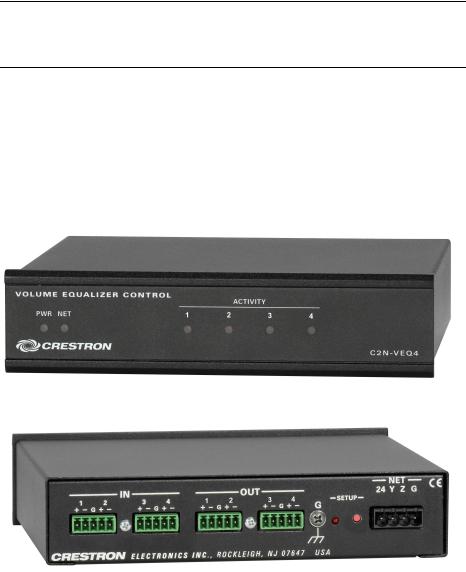
The C2N-VEQ4, shown below, is housed in a black enclosure with labeling on the front and rear panels. Six LEDs on the front of the unit indicate the unit’s status. All connections are made on the back of the unit. There are four rubber feet on the base of the unit for stability and to prevent slippage.
C2N-VEQ4 Physical Views
4 • Cresnet 4-Channel Digital Volume Control: C2N-VEQ4 |
Operations Guide - DOC. 6135A |

Crestron C2N-VEQ4 |
Cresnet 4-Channel Digital Volume Control |
C2N-VEQ4 Overall Dimensions
1.50 in
(3.81 cm)
6.94 in
(17.63 cm)
6.32 in
(16.05 cm)
7.07 in
(17.96 cm)
1.80 in
(4.57 cm) 1.70 in
(4.32 cm)
C2N-VEQ4 Ports
All connections to the C2N-VEQ4 are made through the ports on the rear panel. Refer to the illustrations and descriptions, which follow.
C2N-VEQ4 Ports
IN and OUT Connectors
These four mini connectors provide four channels of balanced/unbalanced audio input (IN 1-4) and four channels of balanced/unbalanced audio output (OUT 1-4). Connect the balanced/unbalanced input (IN) ports to the audio output of any A/V equipment that needs volume, treble, bass, mixer, and/or equalization control. Connect the
Operations Guide - DOC. 6135A |
Cresnet 4-Channel Digital Volume Control: C2N-VEQ4 • 5 |
Cresnet 4-Channel Digital Volume Control |
Crestron C2N-VEQ4 |
balanced/unbalanced output (OUT) ports to an amplifier. Each channel includes a muting relay with 100 dB attenuation.
G (Chassis Ground)
Use this chassis screw to ground the unit to the amplifier and audio source common grounds.
NET
This 4-pin network connector is used to connect the C2N-VEQ4 module to the
Cresnet system. Data and power for the C2N-VEQ4 are provided via the connection.
Refer to “Network Wiring” on page 7.
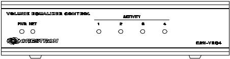
C2N-VEQ4 Indicators
There are six LED indicators located on the front panel of the C2N-VEQ4. Refer to the illustration below and descriptions that follow.
C2N-VEQ4 Indicators
PWR (Power)
This green LED illuminates when power is supplied to the C2N-VEQ4.
NET
This yellow LED illuminates when communication between the control system and the C2N-VEQ4 is established (the unit is polled on the network). Illumination indicates that the program currently loaded has a network device defined at the same ID as the C2N-VEQ4. The LED flashes when communication with the processor occurs.
ACTIVITY (1 – 4)
These red LEDs illuminate only when there is activity on any of the four channels. Activity includes any change in volume, tone (bass, treble), mixer, or equalization parameters. Once the command is completed, the related LED(s) go out.
SETUP LED and Pushbutton
The C2N-VEQ4 is TSID ready. The SETUP pushbutton and its associated LED are located on the rear panel and are used for setup of the unit’s network ID during the initial configuration of a Cresnet® system or when the device is being added/replaced. Refer to “Method B (Touch Settable IDs)” on page 9 for detailed information.
6 • Cresnet 4-Channel Digital Volume Control: C2N-VEQ4 |
Operations Guide - DOC. 6135A |
Crestron C2N-VEQ4 |
Cresnet 4-Channel Digital Volume Control |
Industry Compliance
As of the date of manufacture, the C2N-VEQ4 has been tested and found to comply with specifications for CE marking and standards per EMC and Radiocommunications Compliance Labelling.
NOTE: This device complies with part 15 of the FCC rules. Operation is subject to the following two conditions: (1) these devices may not cause harmful interference, and (2) these devices must accept any interference received, including interference that may cause undesired operation.
Setup
Network Wiring
CAUTION: In order to ensure optimum performance over the full range of your installation topology, Crestron Certified Wire, and only Crestron Certified Wire, should be used. Failure to do so may incur additional charges if support is required to identify performance deficiencies as a result of using improper wire.
CAUTION: Use only Crestron power supplies for Crestron equipment. Failure to do so could cause equipment damage or void the Crestron warranty.
CAUTION: Provide sufficient power to the system. Insufficient power can lead to unpredictable results or damage to the equipment. Please use the Crestron Power Calculator to help calculate how much power is needed for the system (http://www.crestron.com/calculators).
NOTE: When installing network wiring, refer to the latest revision of the wiring diagram(s) appropriate for your specific system configuration, available from the Crestron website.
When calculating the wire gauge for a particular Cresnet run, the length of the run and the Cresnet power usage of each network unit to be connected must be taken into consideration. If Cresnet units are to be daisy-chained on the run, the Cresnet power usage of each unit to be daisy-chained must be added together to determine the Cresnet power usage of the entire chain. If the unit is a home-run from a Crestron system power supply network port, the Cresnet power usage of that unit is the Cresnet power usage of the entire run. The length of the run in feet and the Cresnet power usage of the run should be used in the following resistance equation to calculate the value on the right side of the equation.
Resistance Equation
R < 40,000 L x P
Where: R = Resistance (refer to the following table). L = Length of run (or chain) in feet.
P = Cresnet power usage of entire run (or chain).
Operations Guide - DOC. 6135A |
Cresnet 4-Channel Digital Volume Control: C2N-VEQ4 • 7 |

Cresnet 4-Channel Digital Volume Control |
Crestron C2N-VEQ4 |
Refer to the note on page 26 for a definition of Viewport.
The required wire gauge should be chosen such that the resistance value is less than the value calculated in the resistance equation. Refer to the following table.
Wire Gauge Values
RESISTANCE |
WIRE GAUGE |
|
|
4 |
16 |
|
|
6 |
18 |
10 |
20 |
15 |
22 |
13 |
Doubled CAT 5 |
|
|
8.7 |
Tripled CAT 5 |
|
|
NOTE: All Cresnet wiring must consist of two twisted pairs. One twisted pair is the +24V conductor and the GND conductor, and the other twisted pair is the Y conductor and the Z conductor.
NOTE: When daisy-chaining Cresnet units, strip the ends of the wires carefully to avoid nicking the conductors. Twist together the ends of the wires that share a pin on the network connector, and tin the twisted connection. Apply solder only to the ends of the twisted wires. Avoid tinning too far up the wires or the end becomes brittle. Insert the tinned connection into the Cresnet connector and tighten the retaining screw. Repeat the procedure for the other three conductors.
Identity Code
Every equipment and user interface within the network requires a unique identity code (Net ID). These codes are recognized by a two-digit hexadecimal number from 03 to FE. The Net ID of each unit must match an ID code specified in the SIMPL Windows program. Refer to “Setting the Net ID in Device Settings” on page 15 for details of the SIMPL Windows procedure.
The Net ID of the C2N-VEQ4 has been factory set to 12. The Net IDs of multiple C2N-VEQ4s in the same system must be unique. Net IDs are changed from a personal computer (PC) via the Crestron Viewport.
NOTE: For detailed information on establishing communication between the PC and control system, refer to “Communication Settings” on page 26. If communication cannot be established, refer to the “Troubleshooting Communications” section in the respective Operations Guide for the control system.
There are two different methods—Method A or Method B—for setting the C2N-VEQ4 Net IDs:
Method A (Cresnet address-settable ID), described on page 9, applies to C2N-VEQ4s in a Cresnet system with a CNX control system or with a 2-Series control system upgrade file (CUZ) version prior to 3.008, but can be used with later versions of firmware and requires that a single unit be the only network device connected to the control system.
Method B (Touch Settable IDs), which begins on page 9, applies to C2N-VEQ4s in a Cresnet system with 2-Series control system upgrade file (CUZ) version 3.029 or later. These upgrades enable Touch Settable ID (TSID) functionality, which makes it
8 • Cresnet 4-Channel Digital Volume Control: C2N-VEQ4 |
Operations Guide - DOC. 6135A |
Loading...