


GFX-120/212
GUITAR AMPLIFIER WITH DIGITAL SIGNAL PROCESSING
OWNER’S MANUAL
Congratulations!
You are now the proud owner of the Crate GFX-120/212 guitar amplifier. These rugged amplifiers combine outstanding features with serious clean and distorted sounds. An easy to operate DSP section lets you dial in a variety of digital effects such as delay, flange, chorus and reverb – with separate level control. Channel selection, Crate’s exclusive Shape circuit, and DSP on/off are controllable by the supplied threebutton footswitch. An insert jack allows virtually noise-free connection of your favorite effects.
Like all Crate products, your GFX-120/212 is Musician Made in the U.S.A., using only the best components. Extensive testing at the hands (and ears) of skilled technicians and musicians insures you that this amplifier is the absolute best it can be.
In order to get the most out of your new amplifier, we strongly urge you to go over the information contained in this manual before you begin playing.
And thank you for choosing
GFX-120/212 Amplifier
|
|
|
|
|
|
|
|
|
|
|
|
|
|
|
|
|
|
|
|
|
|
|
|
|
|
|
|
|
|
|
|
|
|
|
|
|
|
|
|
|
|
|
|
|
|
|
|
|
|
|
|
|
|
|
|
|
|
|
|
|
|
|
|
|
|
|
|
|
|
|
|
|
|
|
|
|
|
|
|
|
|
|
|
|
|
|
|
|
|
|
|
|
|
|
|
|
|
|
|
|
|
|
|
|
|
|
|
|
|
|
|
|
|
|
|
|
|
|
|
|
|
|
|
|
|
|
|
|
|
|
|
|
|
|
|
|
|
|
|
|
|
|
|
|
|
|
|
|
|
|
|
|
|
|
|
|
|
|
|
|
|
|
|
|
|
|
|
|
|
|
|
|
|
|
|
|
|
|
|
|
|
|
|
|
|
|
|
|
|
|
|
|
|
|
|
|
|
|
|
|
|
|
|
|
|
|
|
|
|
|
|
|
|
|
|
|
|
|
|
|
|
|
|
|
|
|
|
|
|
|
|
|
|
|
|
|
|
|
|
1 |
2 |
3 |
4 |
5 |
6 |
7 |
8 |
9 |
10 |
11 |
|||||||||||||
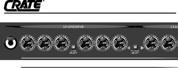
1: INPUT: Connect your guitar here using a shielded instrument cable.
OVERDRIVE CHANNEL: A high gain channel giving you sounds from a slight edge to serious overdrive.
2:GAIN 1: When active, sets the amount of compression and distortion from the amplifier. At far left, the sound will have a thick compressed quality. As you turn the control to the right the amount of distortion increases. Gain 1 produces less intense distortion than Gain 2 and is active only when the Gain Select switch (#5) is out.
3:GAIN 2: When active, sets the amount of compression and distortion from the amplifier. At far left, the sound will have a thick compressed quality. As you turn the control to the right the amount of distortion increases. Gain 2 produces more intense distortion than Gain 1 and is active only when the Gain Select switch (#5) is in.
4:SHAPE: Working in conjunction with the Gain 2 control, rotate the Shape control until you find the sound you’re looking for. Turning the control towards the left enhances the mid frequencies; turning it to the right enhances the low and high frequencies. (Only affects Gain 2 when active.)
5:GAIN SELECT: Switches between Gain 1 (out) and Gain 2 (in). A footswitch (#22) overrides this switch.
6:LOW: Adjusts the low frequency output level: to the left reduces the low frequency output; to the right increases it. This control allows a range of 11dB at 80Hz.
7:HIGH: Adjusts the high frequency output level: to the left reduces the high frequency output, to the right increases it. This control allows a range of 10dB at 10kHz.
8:LEVEL: Sets the output volume level from the Overdrive Channel: in the far-left position there is
no output; turning the control to the right increases the output. Use this control along with the Gain and Shape controls (#2, 3 & 4) to create a wide variety of sounds.
9: CHANNEL SELECT: When this switch is pressed in the Overdrive Channel is engaged. The Clean Channel is selected when this switch is out. A footswitch (#22) overrides this switch. The adjacent LEDs indicate which channel is selected.
CLEAN CHANNEL: A normal gain channel designed to give you crystal clear sounds.
10:LEVEL: Sets the output volume level from the Clean Channel: in the far-left position there is no output; turning the control to the right increases the output level.
11:LOW: Adjusts the low frequency output level: to the left reduces the low frequency output; to the right increases it. This control allows a range of 22dB at 80Hz.
12:MID: Adjusts the mid frequency output level: to the left reduces the midrange output; turning it to the right increases it. This control allows a range of 14dB at 600Hz.
13:HIGH: Adjusts the high frequency output level: to the left reduces the high frequency output; to the right increases it. This control allows a range of 28dB at 10kHz.
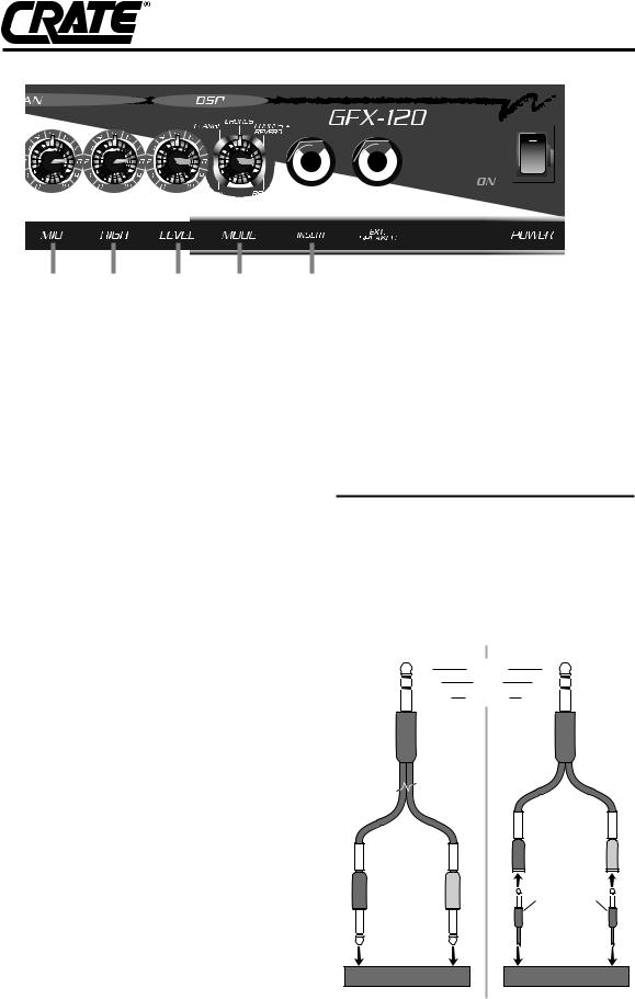
14:DSP LEVEL: Adjust the amount of digital signal processing with this control: in the full-left position the output signal is “dry” (no effect); rotating the control to the right increases the amount of effect. The DSP can be turned on and off with a footswitch (#23).
15:DSP MODE: Select the type of digital effect(s) desired with this control. Each category and its central location is called out (delay, flange, etc.) by the markings around the control; there are two variations per effect, as follows:
GFX-120/212 Amplifier
12 |
13 |
14 |
15 |
16 |
•Slapback delay
•Long delay w/regeneration
•Light Flange
•Heavy Flange
•Slow Chorus
•Fast Chorus
•Chorus w/small room reverb
•Chorus w/large room reverb
•Small room reverb
•Large room reverb
16:INSERT: Connect an external effects device via this jack. Use a stereo 1/4” male Y-cord: ring = send, tip = return, sleeve = ground. See the illustration on the panel to the right for more information.
17:EXT. SPEAKER: Connect to an extension speaker cabinet with this jack. The jack is wired in series with the internal speaker(s).
18:POWER ON LED: Lights when the amplifier is turned on.
19:POWER SWITCH: Turns the amplifier ON in the up position, off in the down position.
20. POWER CORD (rear panel, not shown): Your GFX-120/212 is equipped with a heavy-duty grounded three-wire power cord. Be sure this cord is properly plugged into a safely wired grounded 120 volt, 60Hz AC power outlet before use. (If your GFX-120/212 was purchased outside the United States, refer to the rear panel for power ratings.) For your safety, never attempt to defeat the ground connection on this cord.
21: FUSE (rear panel, not shown): Protects the amplifier against damages caused from a faulty AC power source or other problems. If the fuse blows, replace it ONLY with the same size and type fuse. If the fuse blows repeatedly check the AC source; if it’s okay, contact your Crate dealer for service information.
|
|
|
|
|
|
|
|
|
|
|
|
|
|
|
|
|
|
|
|
|
|
|
|
|
|
|
|
17 |
18 |
19 |
|
|||
22:CHANNEL SELECT / GAIN FOOTSWITCH JACK (rear panel, not shown): Connect the stereo 1/4” plug of the supplied three-button footswitch here for remote control of the Channel Select and Gain Select settings.
23:DSP FOOTSWITCH JACK (rear panel, not shown): Connect the mono 1/4” plug of the supplied three-button footswitch here for remote control of the DSP on and off.
Connecting to the Insert jack:
The Insert jack (#16) lets you patch external effects into the amplifier just prior to its power amp stage. Use Crate’s STP201, STP202 or STP203 stereo- to-mono Y-cord or an adapter such as Crate’s YPP117 and 2 1/4” mono signal cables to connect to the effect as shown below.
Stereo-to-mono Y-cord: |
Y-adapter and 2 cables: |
||||
to Insert |
TIP |
|
RETURN |
TIP |
to Insert |
jack |
RING |
|
SEND |
RING |
jack |
|
SLEEVE |
|
GROUND |
SLEEVE |
|
(STP201, 3' |
|
|
|
(YPP117) |
|
STP202, 6' |
|
|
|
|
|
STP203, 9') |
|
|
|
|
|
|
|
|
|
T |
I R |
|
|
|
|
P I |
G N |
T |
|
I R |
|
|
|
P I |
|
G N |
|
|
|
|
|
|
|
(1/4"-TO-1/4" |
|
|
|
|
|
MONO SHIELDED |
|
|
|
|
|
CABLES) |
|
to |
to |
|
|
to |
to |
effect |
effect |
|
|
effect |
effect |
"OUT" |
"IN" |
|
|
"OUT" |
"IN" |
jack |
jack |
|
|
jack |
jack |
External Effect |
|
|
External Effect |
||
|
|
|
GFX-120/212 Amplifier |
|
|
|
|
|
GFX-120/212 TECHNICAL SPECIFICATIONS |
|
|
||
|
|
|
|
|
|
|
|
|
Output Power Rating |
|
115 watts RMS @ 5% THD 4 ohms load 120VAC |
|
|
|
|
Speaker Size and Rating |
GFX-120: (1) Custom Design 12”, 4 ohms |
|
|
|
|
|
|
|
GFX-212: (2) Crate Custom 12”, 8 ohms |
|
|
|
|
|
|
|
|
|
|
|
Input Impedance |
|
470k ohms |
|
|
|
|
|
|
|
|
|
|
|
Maximum Input Signal Level Accepted |
7 volts, peak-to-peak |
|
|
|
|
|
|
|
|
|
|
|
|
Total System Gain |
|
Overdrive Channel: 110dB all controls @10, Gain 2; 88dB Gain 1 |
|
|
|
|
|
|
Clean Channel: 58dB all controls @10 |
|
|
|
|
|
|
|
|
|
|
|
Overdrive Channel: |
Low Control: |
11dB Range @ 80Hz |
|
|
|
|
|
Shape Control: |
Proprietary Circuit |
|
|
|
|
|
High Control: |
10dB Range @ 10kHz |
|
|
|
|
|
|
|
|
|
|
|
Clean Channel: |
Low Control: |
22dB Range @ 80Hz |
|
|
|
|
|
Mid Control: |
14dB Range @ 600Hz |
|
|
|
|
|
High Control: |
28dB Range @ 10kHz |
|
|
|
|
|
|
|
|
|
|
|
Input Power Requirements |
120 VAC, 60Hz, 95VA |
|
|
|
|
|
|
|
100/115VAC, 50/60Hz, 95VA |
|
|
|
|
|
|
230VAC, 50/60Hz, 95VA |
|
|
|
|
|
|
|
|
|
|
|
Cabinet Size and Weight: |
GFX-120: 17-1/2” H x 19-1/4” W x 9-3/4” D, 44 lbs. |
|
|
|
|
|
|
|
GFX-212: 21” H x 26-1/2” W x 11” D, 50 lbs. |
|
|
|
|
|
|
|
|
|
|
|
|
|
|
|
|
The GFX-120/212 is covered with a durable Tolex material: wipe it clean with a lint-free cloth. Never spray cleaning agents onto the cabinet. Avoid abrasive cleansers which could damage the finish.
CAUTION |
RISK OF ELECTRIC SHOCK |
DO NOT OPEN |
CAUTION: TO REDUCE THE RISK OF ELECTRIC SHOCK, |
DO NOT REMOVE COVER. |
NO USER-SERVICEABLE PARTS INSIDE. |
REFER SERVICING TO QUALIFIED SERVICE PERSONNEL. |
ATTENTION
RISQUE D'ELECTROCUTION
NE PAS OUVRIR
ATTENTION: POUR REDUIRE D'ELECTROCUTION NE PAS ENLEVER LE COUVERCLE. AUCUNE PIECE INTERNE N'EST REPRABLE PAR L'UTILISATEUR. POUR TOUTE REPARATION, S'ADRESSER A UN
TECHNICIEN QUALIFIE.
VORSICHT |
ELEKTRISCHE SCHLAGGEFAHR |
NICHT OFFENEN |
VORSICHT: ZUR MINIMIERUNG ELEKTRISCHER SCHLAGGEFAHR NICHT |
DEN DECKEL ABENHMEN. INTERNE TEILE KONNEN NICHT VOM |
BENUTZER GEWARTET WERDEN. DIE WARTUNG IS QUALIFIZIERTEM |
WARTUNGSPERSONAL ZU UBERLASSEN. |
THIS EQUIPMENT HAS BEEN DESIGNED AND ENGINEERED TO PROVIDE SAFE AND RELIABLE OPERATION. IN ORDER TO PROLONG THE LIFE OF THE UNIT AND PREVENT ACCIDENTAL DAMAGES OR INJURY, PLEASE FOLLOW THESE PRECAUTIONARY GUIDELINES:
CAUTION: TO REDUCE THE RISK OF ELECTRIC SHOCK, DO NOT OPEN CHASSIS; DO NOT DEFEAT OR REMOVE THE GROUND PIN OF THE POWER CORD; CONNECT ONLY TO A PROPERLY GROUNDED AC POWER OUTLET.
WARNING: TO REDUCE THE RISK OF FIRE OR ELECTRIC SHOCK, DO NOT EXPOSE THIS EQUIPMENT TO RAIN OR MOISTURE.
CAUTION: NO USER-SERVICEABLE PARTS INSIDE. REFER SERVICING TO QUALIFIED SERVICE PERSONNEL.
CAUTION: OUR AMPLIFIERS ARE CAPABLE OF PRODUCING HIGH SOUND PRESSURE LEVELS. CONTINUED EXPOSURE TO HIGH SOUND PRESSURE LEVELS CAN CAUSE PERMANENT HEARING IMPAIRMENT OR LOSS. USER CAUTION IS ADVISED AND EAR PROTECTION IS RECOMMENDED IF UNIT IS OPERATED AT HIGH VOLUME.
EXPLANATION OF GRAPHICAL SYMBOLS: |
"DANGEROUS VOLTAGE" |
EXPLICACION DE SIMBOLOS GRAFICOS: |
= “VOLTAJE PELIGROSO” |
EXPLICATION DES SYMBÔLES GRAPHIQUES: |
"DANGER HAUTE TENSION" |
"GEFAHLICHE SPANNUNG" |
"IT IS NECESSARY FOR THE USER TO REFER TO THE INSTRUCTION MANUAL"
=“ES NECESARIO QUE EL USUARIO SE REFIERA AL MANUAL DE INSTRUCCIONES.” "REFERREZ-VOUS AU MANUAL D'UTILISATION"
"UNBEDINGT IN DER BEDIENUNGSANLEITUNG NACHSCHLAGEN"
Crate continually develops new products, as well as improves existing ones. For this reason, the specifications and information in this Crate manual are subject to change without notice.
www.crateamps.com
©2001 SLM ELECTRONICS, A DIVISION OF ST. LOUIS MUSIC, 1400 FERGUSON, ST. LOUIS, MO. 63133
P/N 47-476-03 • 05/01
 Loading...