


Operator’s Manual
10″
CONTRACTOR TABLE SAW
Model No.
351.218330
CAUTION:
Read and follow all Safety Rules and Operating Instructions before First Use of this Product. Keep this Manual with Tool.
¥Safety
¥Unpacking
¥Assembly
¥Operation
¥Maintenance
¥Parts List
¥Español
Sears Brands Management Corp., Hoffman Estates, IL 60179 U.S.A.
www.sears.com/craftsman
31105.04 Draft (02/09/10)

TABLE OF CONTENTS
Warranty. . . . . . . . . . . . . . . . . . . . . . . . . . . . . . . . . . . . . . . . . 2
Safety Rules . . . . . . . . . . . . . . . . . . . . . . . . . . . . . . . . . . . . 2-5
Unpacking. . . . . . . . . . . . . . . . . . . . . . . . . . . . . . . . . . . . . . 5-6
Assembly . . . . . . . . . . . . . . . . . . . . . . . . . . . . . . . . . . . . . 6-13
Installation. . . . . . . . . . . . . . . . . . . . . . . . . . . . . . . . . . . . 13-14
Operation . . . . . . . . . . . . . . . . . . . . . . . . . . . . . . . . . . . . 14-19
Maintenance . . . . . . . . . . . . . . . . . . . . . . . . . . . . . . . . . . 19-20
Repair Protection Agreement . . . . . . . . . . . . . . . . . . . . . . . 20
Troubleshooting . . . . . . . . . . . . . . . . . . . . . . . . . . . . . . . 22-23
Parts Illustration and List . . . . . . . . . . . . . . . . . . . . . . . . 24-35
Espa–ol. . . . . . . . . . . . . . . . . . . . . . . . . . . . . . . . . . . . . . 36-59
WARRANTY
ONE-YEAR FULL WARRANTY ON CRAFTSMAN TOOL
If this Craftsman tool fails due to a defect in material or workmanship within one year from the date of purchase, call 1-800-4-MY-HOME¨ TO ARRANGE FOR FREE REPAIR (or replacement if repair proves impossible).
This warranty does not cover the blade, which is an expendable part.
If this tool is ever used for commercial or rental purposes, this warranty will apply for only 90 days from the date of purchase.
This warranty gives you specific legal rights and you may also have other rights which vary from state to state.
Sears, Roebuck and Co., Hoffman Estates, IL 60179
SAFETY RULES
WARNING: For your own safety, read all of the instructions and precautions before operating tool.
PROPOSITION 65 WARNING: Some dust created by using power tools contain chemicals known to the state of California to cause cancer, birth defects or other reproductive harm.
Some examples of these chemicals are:
¥Lead from lead-based paints.
¥Crystalline silica from bricks and cement and other masonry products.
¥Arsenic and chromium from chemically-treated lumber.
Your risk from these exposures vary, depending on how often you do this type of work. To reduce your exposure to these chemicals: work in a well ventilated area and work with approved safety equipment. Always wear OSHA/NIOSH approved, properly fitting face mask or respirator when using such tools.
CAUTION: Always follow proper operating procedures as defined in this manual Ñ even if you are familiar with use of this or similar tools. Remember that being careless for even a fraction of a second can result in severe personal injury.
BE PREPARED FOR JOB
¥Wear proper apparel. Do not wear loose clothing, gloves, neckties, rings, bracelets or other jewelry which may get caught in moving parts of machine.
¥Wear protective hair covering to contain long hair.
¥Wear safety shoes with non-slip soles.
¥Wear safety glasses complying with United States ANSI Z87.1. Everyday glasses have only impact resistant lenses. They are NOT safety glasses.
¥Wear face mask or dust mask if operation is dusty.
¥Be alert and think clearly. Never operate power tools when tired, intoxicated or when taking medications that cause drowsiness.
PREPARE WORK AREA FOR JOB
¥Keep work area clean. Cluttered work areas invite accidents.
¥Do not use power tools in dangerous environments. Do not use power tools in damp or wet locations. Do not expose power tools to rain.
¥Work area should be properly lighted.
¥Keep visitors at a safe distance from work area.
¥Keep children out of workplace. Make workshop childproof. Use padlocks, master switches or remove switch keys to prevent any unintentional use of power tools.
¥Keep power cords from coming in contact with sharp objects, oil, grease and hot surfaces.
TOOL SHOULD BE MAINTAINED
¥Always unplug tool prior to inspection.
¥Consult manual for specific maintaining and adjusting procedures.
¥Keep tool lubricated and clean for safest operation.
¥Remove adjusting tools. Form habit of checking to see that adjusting tools are removed before switching machine on.
¥Keep all parts in working order. Check to determine that the guard or other parts will operate properly and perform their intended function.
¥Check for damaged parts. Check for alignment of moving parts, binding, breakage, mounting and any other condition that may affect a toolÕs operation.
¥A guard or other part that is damaged should be properly repaired or replaced. Do not perform makeshift repairs. (Use parts list provided to order replacement parts.)
¥Maintain proper adjustment of rip fence and blade guard.
¥Never adjust saw while running. Disconnect power to avoid accidental start-up.
¥Have damaged or worn power cords replaced immediately.
¥Keep blade sharp for efficient and safest operation.
KNOW HOW TO USE TOOL
¥Use right tool for job. Do not force tool or attachment to do a job for which it was not designed.
¥Disconnect tool when changing blade.
¥Avoid accidental start-up. Make sure that the tool is in the ÒoffÓ position before plugging in, turning on safety disconnect or activating breakers.
¥Do not force tool. It will work most efficiently at the rate for which it was designed.
¥Keep hands away from blade and moving parts and cutting surfaces.
¥Never leave tool running unattended. Turn the power off and do not leave tool until it comes to a complete stop.
¥Do not overreach. Keep proper footing and balance.
¥Never stand on tool. Serious injury could occur if tool is tipped or if blade is unintentionally contacted.
© Sears, Roebuck and Co.
2
¥Know your tool. Learn the toolÕs operation, application and specific limitations.
¥Handle workpiece correctly. Press firmly against table. Protect hands from possible injury.
¥Turn machine off if it jams. Blade jams when it digs too deeply into workpiece. (Motor force keeps it stuck in the work.)
¥Feed work into the blade only as recommended in ÒOperation.Ó
WARNING: For your own safety, do not operate your saw until it is completely assembled and installed according to instructions.
STABILITY OF SAW
If there is any tendency for the saw to tip over or move during certain cutting operations, such as cutting extremely heavy panels or long heavy boards, the saw should be bolted down. If you attach any kind of extensions over 24″ wide to either end of the saw, make sure you either bolt the saw to the floor, as appropriate, or support the outer end of the extension from the bench or floor, as appropriate.
LOCATION
The saw should be positioned so neither the operator nor a casual observer is forced to stand in line with the saw blade.
KICKBACKS
A kickback occurs during a rip-type operation when a part or all of workpiece is thrown back violently toward operator.
Keep your face and body to one side of the saw blade, out of line with a possible kickback.
Kickbacks and possible injury from them can usually be avoided by:
¥Maintaining rip fence parallel to saw blade.
¥Keeping saw blade sharp. Replace or sharpen anti-kick- back pawls when points become dull.
¥Keeping saw blade guard, spreader, and anti-kickback pawls in place and operating properly. The spreader must be in alignment with the saw blade and the pawls must stop a kickback once it has started. Check their action before ripping.
¥Not ripping work that is twisted or warped or does not have a straight edge to guide along the rip fence.
¥Not releasing work until you have pushed it all the way past the saw blade.
¥Using a push stick for ripping widths less than 6 inches.
¥Not confining the cutoff piece when ripping or crosscutting.
PROTECTION: EYES, HANDS, FACE, BODY, EARS
¥If any part of your saw is missing, malfunctioning , or has been damaged or broken (such as the motor switch, electronic controls, other operating control, a safety device or power cord), cease operating immediately until the particular part is properly repaired or replaced.
¥Wear safety goggles that comply with United States ANSI Z87.1 and a face shield or dust mask if operation is dusty. Wear ear plugs or muffs during extended periods of operation.
¥Small loose pieces of wood or other objects that contact the rear of the revolving blade can be thrown back at the operator at excessive speed. This can usually be avoided by keeping the guard and spreader in place for all thrusawing operations (sawing entirely thru work) and by removing all loose pieces from the table with a long stick of wood immediately after they are cut off.
¥Use extra caution when the guard assembly is removed for resawing, dadoing, or rabbetingÑreplace guard as soon as that operation is completed.
¥Never turn the saw ON before clearing the table of all tools, wood scraps, etc., except the workpiece and related feed or support devices for the operation planned.
¥Never place your face or body in line with the cutting tool.
¥Never place your fingers or hands in path of saw blade or other cutting tool.
¥For rip or rip-type cuts, the following end of a workpiece to which a push stick or push board is applied must be square (perpendicular to the fence) in order that feed pressure applied to the workpiece by the push stick or block does not cause the workpiece to come away from the fence, and possibly cause a kickback.
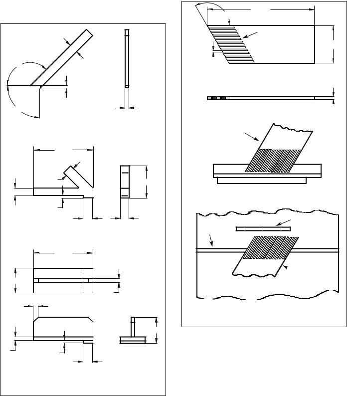
¥During rip and rip-type cuts, workpiece must be held down on table and against fence with a push stick, push block, or featherboards, as applicable (see Figures 1a and 1b, page 4).
The push stick and push block examples shown below are useful for keeping hands and fingers away from saw blade during ripping, rabbeting and dadoing. Apply downward pressure and push workpiece through the cut and past the blades. Several other configurations may be suitable for safe operation.
Featherboards are used to keep the work in contact with the rip fence or table during the cutting operation. Use of featherboards can help to prevent kickbacks and binding. Featherboards should be used for all Ònon thru-sawingÓ operations.
¥Never reach in back of the cutting tool with either hand to hold down or support the workpiece, remove wood scraps, or for any other reason. Avoid awkward operations and hand positions where a sudden slip could cause fingers or hand to move into a saw blade or other cutting tool.
¥Do not perform layout, assembly, or setup work on the table while the cutting tool is rotating.
¥Do not perform any operation freehandÑalways use either rip fence or miter gauge to position and guide the work.
¥Never use the rip fence when cross-cutting or the miter gauge when ripping. Do not use rip fence as a length stop. Never hold onto or touch free-end of workpiece or a free-piece that is cut off, while power is ON and/or saw blade is rotating.
¥Shut the saw OFF and disconnect power source when removing the table insert, changing the cutting tool, removing or replacing the blade guard, or making adjustments.
¥Provide adequate support to the rear and sides of the saw table for wide or long workpieces.
¥Plastic and composition materials (like hardboard) may be cut on your saw. However, since these are usually quite hard and slippery, the anti-kickback pawls may not stop a kickback. Therefore, be especially attentive to following proper setup and cutting procedures for ripping. Do not stand, or permit anyone else to stand, in line with a potential kickback.
¥If you stall or jam the saw blade in the workpiece, turn saw OFF and remove the workpiece from the saw blade. Check to see if the saw blade is parallel to the miter gauge grooves and if the spreader is in proper alignment with the saw blade. If ripping at the time, check to see if the rip fence is parallel with the saw blade. Readjust as required.
¥Do not remove small pieces of cutoff material that may become trapped inside the blade guard while the saw is running. This could endanger your hands or cause kickback. Turn saw OFF and wait until blade stops.
3
¥Use extra care when ripping wood with twisted grain or wood that is twisted or bowedÑit may rock on table and pinch saw blade.
|
1¾″ |
|
|
135¡ |
″ |
Long |
|
|
|
||
15 |
|
|
|
|
|
|
|
|
½″ |
|
|
90¡ |
|
|
¾″ |
|
|
12″ |
|
1½″ |
2″ |
|
6½″ |
|
|
||
|
|
|
|
|
½″ |
|
|
|
|
2″ |
1¾″ |
|
|
12″ |
|
5″ |
|
|
|
|
|
|
¾″ |
|
1″ x 45¡ (2X) |
|
|
|
|
|
5¼″ |
¾″ |
½″ |
|
|
|
|
||
|
|
2″ |
|
Figure 1a - Push Sticks and Push Blocks |
|
||
KNOW YOUR CUTTING TOOLS
¥Dull, gummy, improperly sharpened or set cutting tools can cause material to stick, jam, stall saw, or kickback at operator. Minimize potential injury by proper care and machine maintenance.
WARNING: Never attempt to free a stalled saw blade without first turning saw OFF.
¥Never use grinding wheels, abrasive cutoff wheels, friction wheels (metal slitting blades), wire wheels or buffing wheels.
24″
120¡
5″ Long (typ.)
|
|
Solid Lumber |
8 7Ú16″ |
|
|
5Ú16″ (typ.) 
3Ú4″ 
Clamp to rip fence or rip fence extension to keep work on the table.
Rip Fence |
Table |
Blade
Miter slot
 Clamp to table to guide work
Use featherboards in combinations as required to control workpieces.
Figure 1b - Featherboards
USE ONLY ACCESSORIES DESIGNED FOR SAW
¥Crosscutting operations are worked more conveniently and with greater safety if an auxiliary wood facing is attached to miter gauge using holes provided. However, facing must not interfere with proper functioning of saw blade guard.
¥Make sure the top of the arbor or cutting tool rotates toward you when standing in normal operating position. Also make sure the cutting tool, blade flange and arbor nut are installed properly. Keep the cutting tool as low as possible for the operation being performed. Keep all guards in place whenever possible.
¥Do not use any blade or other cutting tool marked for operating speed less than 4000 RPM. Never use a cutting tool larger in diameter than diameter for which saw was designed. For greatest safety and efficiency when ripping, use maximum diameter blade for which saw is designed, since under these conditions spreader is nearest the blade.
¥Adjust table inserts flush with table top. Never operate saw unless proper insert is installed.
4

¥Never feed material into the cutting tool from the rear of the saw. An accident and serious injury could result.
THINK SAFETY
Safety is a combination of operator common sense and alertness at all times when the saw is being used.
Never use another person as a substitute for a table extension, or as additional support for a workpiece that is longer or wider than basic saw table, or to assist in feeding, supporting or pulling the workpiece.
Do not pull the workpiece through the saw bladeÑposition your body at the infeed side of the guard; start and complete the cut from that same side. This will require added table support for long or wide workpieces that extend beyond the length or width of the saw table.
CAUTION: Follow safety instructions that appear on the front of your saw.
UNPACKING
Refer to Figure 2.
¥Open shipping box. Remove all parts, except saw body, from both styrofoam packing bases and set parts and top base safely aside.
¥Use utility knife to cut down the four corners of the shipping box, fully exposing the bottom packing base.
¥Cut away enough styrofoam from motor cover side of packing base so that, with the aid of an assistant, you can slide the saw body from the base.
CAUTION: Do not attempt assembly if parts are missing. Use this manual to order replacement parts.
Check for shipping damage or missing parts. If any parts are damaged or missing, call 1-800-266-9079 for replacement.
The table saw body comes assembled as one unit. Additional parts which need to be fastened to the saw should be located and accounted for before assembling:
A Extension Table (2) B Dust Chute
C Front Rail (2)
D Rear Rail (2)
E Miter Gauge Assembly
F Blade Guard Assembly G Dado Insert
H Table Insert
I Handwheel Assembly with Knob (2) J Rip Fence Assembly
KRubber Foot (4)
L Anti-kickback Pawl Assembly
M Line Cord Hooks (2)
N Brace
O Rip Fence Storage Hooks (2)
P Blade Guard Storage Hooks (2)
Q Push Stick Storage Hooks (2)
R Push Stick
SBase Panel (4)
T Corner Support (4)
U Caster Set (2)
Hardware Bag #1
M10 x 25 Socket Head Bolt (6)
M10 Lock Washer (6)
M10 Flat Washer (6)
Hardware Bag #2
M8 x 28 Hex Head Bolt (8)
M8 x 25 Hex Head Bolt (8)
M8 x 20 Hex Head Bolt (4)
M8 Lock Washer (20)
M8 Flat Washer (20)
M8 Hex Nut (16)
M8 Acorn Hex Nut (4)
Hardware Bag #3
M6 x 16 Hex Head Screw (2)
M6 Flat Washer (2)
M6 Hex Nut (2)
M6 Lock Washer (2)
Hardware Bag #4
M10 x 25 Socket Head Bolt (4)
M8 x 16 Socket Pan Head Screw (8)
M6 x 12 Socket Pan Head Screw (24)
M6 x 16 Socket Head Bolt (2)
M5 x 12 Socket Head Bolt (4)
M3 x 10 Pan Head Screw (4)
M10 Lock Washer (4)
M6 Hex Nut (2)
M5 Lock Washer (4)
M3 Lock Washer (4)
M10 Flat Washer (4)
M6 Flat Washer (2)
M5 Flat Washer (4)
M3 Flat Washer (4)
Hardware Bag #5
10/13mm Open End Wrench 4mm Hex Wrench
5mm Hex Wrench 8mm Hex Wrench
A
|
C |
B |
|
|
|
|
D |
|
|
|
L |
I |
|
K |
|
|
|
|
|
J |
|
|
N |
|
|
Q |
R U
T
S
Figure 2 - Unpacking
E
F
GH
M
O
P
5
IMPORTANT: Table is coated with a protectant. To ensure proper fit and operation, remove coating. Coating is easily removed with mild solvents, such as mineral spirits, and a soft cloth. Avoid getting solution on paint or any of the rubber or plastic parts. Solvents may deteriorate these finishes. Use soap and water on paint, plastic or rubber components. After cleaning, cover all exposed surfaces with a light coating of oil. Paste wax is recommended for table top.
WARNING: Never use highly volatile solvents. Non flammable solvents are recommended to avoid possible fire hazard.
ASSEMBLY
Refer to Figures 3-34.
CAUTION: Do not attempt assembly if parts are missing. Use this manual to order replacement parts.
Be certain all parts are clean and free of shipping preservative. Also, completely remove all parts of packing. Saw cabinet should be directly on the floor.
SAW INSTALLATION
Positioning the saw on a level surface will improve stability and accuracy and prevent warpage and failure of cast components and welds.
WARNING: Make certain that the saw is disconnected from the power source.
INSTALL HANDWHEELS
Refer to Figure 3.
¥Remove saw cabinet and place upside down on cardboard box or cardboard on floor.
¥Place one of the handwheels onto the blade raise/lower shaft located on the front of the cabinet. Align the groove in the back of the handwheel with the pin.
¥Thread the washer and locking knob onto the threaded end of the shaft.
¥Repeat the steps above to assemble the remaining handwheel and locking knob onto the blade tilt shaft located on the side of the cabinet.
Blade Raise Handwheel
Blade Tilt
Handwheel
Figure 3
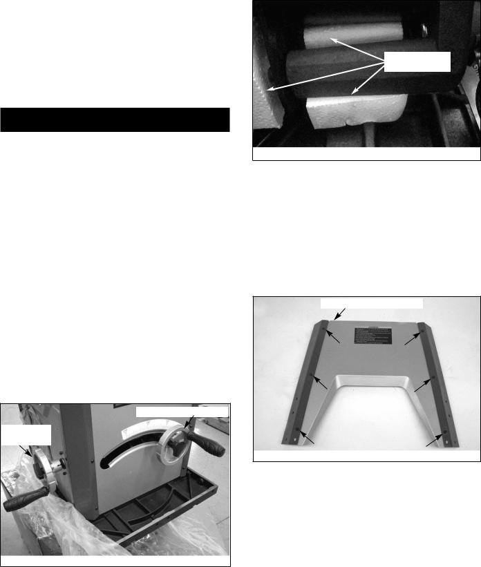
REMOVE PACKING MATERIAL
Refer to Figure 4.
¥Use the blade tilt handwheel to tilt the motor completely to 45¡.
¥Remove the packing material from behind the motor.
¥Return motor to the 0¡ position.
Remove this packing material
Figure 4
ASSEMBLE MOBILE BASE PANELS
Refer to Figures 5 and 6, pages 6 and 7. Tools Required: 4mm Hex Wrench
Hardware Required: Twenty-four M6 x 12 socket pan head bolts (Hardware bag #4).
¥Attach the front panel between two corner supports using six M6 x 12 socket pan head screws.
NOTE: Place the panel edges INSIDE the corner support surfaces.
NOTE: Front panel and rear panel are both stamped ÔAÕ. Front panel has warning label.
¥Repeat above step for the rear panel.
Letter Stamp On Top Edge
Figure 5
¥Turn all panels upside down to perform base assembly.
¥Attach one corner of left panel (stamped ÔBÕ) to front panel A.
¥Attach the other corner of left panel B to rear panel A.
¥Repeat above two steps for attachment of right panel (stamped ÔCÕ).
6
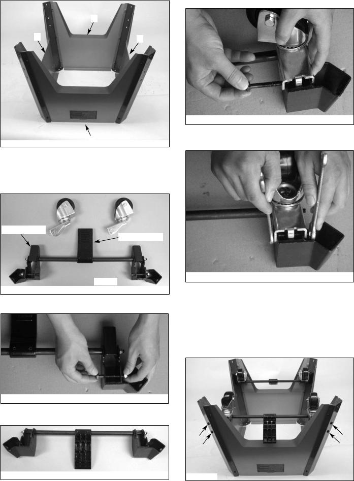
Below is completed base assembly.
A
C |
B |
|
A
Figure 6
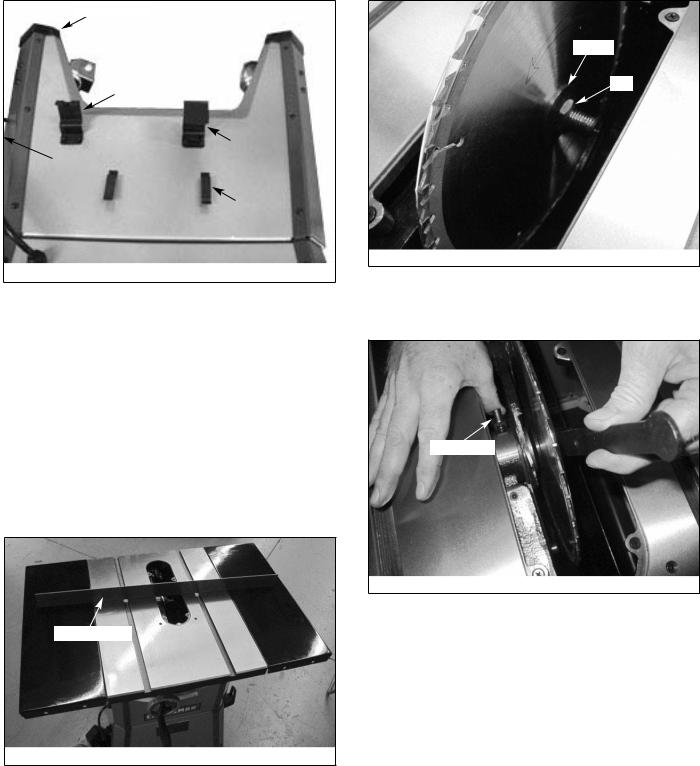
ASSEMBLE CASTER SETS
Refer to Figures 7-11.
Tools Required: Two 1Ú2″ Open End Wrenches
¥Refer to Figure 7; remove casters (4) and supports (2) from carton.
Kick Plate Cam
Foot Pedal Bar
Bracket
Figure 7
¥Loosen and remove the bolt and hex nut from the bracket (see Figure 8)
Figure 8
¥Rotate foot pedal bar so that kick plate cam is inside bracket (see Figure 9).
Figure 9 - Kick Plate Cams Inside the Brackets
¥The kick plate cam must be underneath the caster to function properly (see Figure 10).
Figure 10
¥Refer to Figures 10 and 11; place caster onto the bracket and secure in position with bolt and hex nut.
¥Repeat above steps for the second caster set.
Figure 11
ATTACH CASTER SETS TO BASE
Refer to Figure 12.
Tools Required: 5mm Hex Wrench
Hardware Required: Eight M8 x 16 socket pan head screws (Hardware bag #4).
¥Attach one caster set to the two front corner supports using four M8 x 16 socket pan head screws.
¥Attach the remaining caster set to the two rear corner supports.
Figure 12
7
ATTACH CORD WRAP HOOKS
Refer to Figure 13.
Tools Required: 4mm Hex Wrench
Hardware Required: Two M6 x 16 socket pan head bolts, two M6 flat washers and two M6 hex nuts (Hardware bag #4).
¥Insert a bolt into a cord wrap hook and place against the holes on the left side of the saw cabinet.
¥Secure hook in position using flat washer and hex nut.
¥Repeat for other hook.
Figure 13
ATTACH BASE TO CABINET
Refer to Figures 14 and 15.
Tools Required: 8mm Hex Wrench
Hardware Required: Four M10 x 25 socket head bolts, four M10 lock washers and four M10 flat washers (Hardware bag #4).
¥Place dust chute over the cabinet as shown. Make sure the holes in the corners are aligned with the slots in the dust chute.
Figure 14
¥Place the base assembly over the dust chute and secure the base assembly to the cabinet using the flat washers, lock washers and bolts.
¥Secure all fasteners in the base assembly fully tight.
Figure 15
ATTACH RIP FENCE BRACKETS
Refer to Figure 16.
Tools Required: 5mm Hex Wrench
Hardware Required: Two M6 x 16 socket head bolts, two M6 flat washers and two M6 hex nuts (Hardware bag #4).
¥Install the rip fence storage brackets to the right side panel of the base using two bolts, flat washers and hex nuts.
Figure 16
BLADE GUARD AND PUSH STICK STORAGE BRACKETS
Refer to Figure 17, page 9.
Tools Required: Phillips screwdriver and 4mm hex wrench
Hardware Required: Four M3 x 10 pan head screws, four M3 lock washers, four M3 flat washers, four M5 x 12 socket head bolts, four M5 lock washers and four M5 flat washers (Hardware bag #4).
¥Install the push stick storage brackets to the left side panel of the base using four screws, lock washers and flat washers.
¥Install the blade guard storage brackets to the left side panel of the base using four screws, lock washers and flat washers.
NOTE: Attach the slotted bracket to the front side of the saw.
¥Press the four rubber feet to the base legs.
¥With the aid of an assistant turn the saw upright. WARNING: To avoid injury, Do Not attempt to turn saw upright by yourself.
8
Rubber Feet
Slotted Bracket |
|
|
|
|
|
|
|
|
|
|
|
Blade Guard |
||
|
|
Bracket |
||
Front Side of Saw |
|
|||
|
|
|
|
|
|
|
|
|
|
|
|
|
Push Stick |
|
|
|
|
Bracket |
|
Figure 17
ATTACH EXTENSION TABLES
Refer to Figure 18.
Tools Required: 8mm Hex Wrench and Straight Edge
Hardware Required: Six M10 x 25 socket head bolts, six M10 lock washers and six M10 flat washers (Hardware bag #1).
¥Assemble extension table to the table using socket head bolts, lock washers and flat washers.
¥Wipe surface clean.
¥Hand tighten only. Do not tighten completely until tables are level. Use a straightedge to level tables.
¥Repeat above procedure for the other extension table.
¥Use a straight edge to check level and flatness between main and extension tables.
¥After tables are adjusted level and flat, secure the extension tables by tightening the bolts completely.
Straight Edge
Figure 18
INSTALL BLADE
Refer to Figures 19 and 20.
Tools Required: 13mm Open end Wrench
¥Loosen knob on right side of cabinet.
¥Remove blade and wrench. Replace knob.
¥Raise blade assembly all the way up.
¥Depress arbor lock and use wrench to loosen flange nut. Remove flange and nut from arbor.
Flange
Nut
Figure 19
¥Place blade on arbor. Make sure arrow on blade and teeth point towards front of saw.
¥Replace flange and nut on arbor and securely snug blade in position.
Arbor Lock
Figure 20
CHECK TABLE ALIGNMENT
Refer to Figures 21, 22 and 23, page 10.
¥Saws are shipped from the factory with the table adjusted so the miter gauge slots are parallel to the saw blade. However, in order to obtain the best results from the saw, it is suggested this adjustment be checked before operating.
¥A simple method of checking alignment is as follows: Bolt or clamp a dowel rod or similar object to miter gauge (a combination square can be substituted). Pick out a tooth on front of blade and set the dowel to it so it is just touching. Move same tooth to back of blade.
¥Gauge this tooth with the dowel rod. If the tooth is in the same position, relative to the miter gauge slot, the table is parallel with the blade. In short, the miter gauge slots must be parallel with the blade. This means that when measuring distance between blade and miter gauge slot at the front and rear of the blade, the distances will be equal (see Figure 21).
NOTE: Be sure to measure the distance or make the test on the same tooth of the saw blade in both front and rear positions.
9
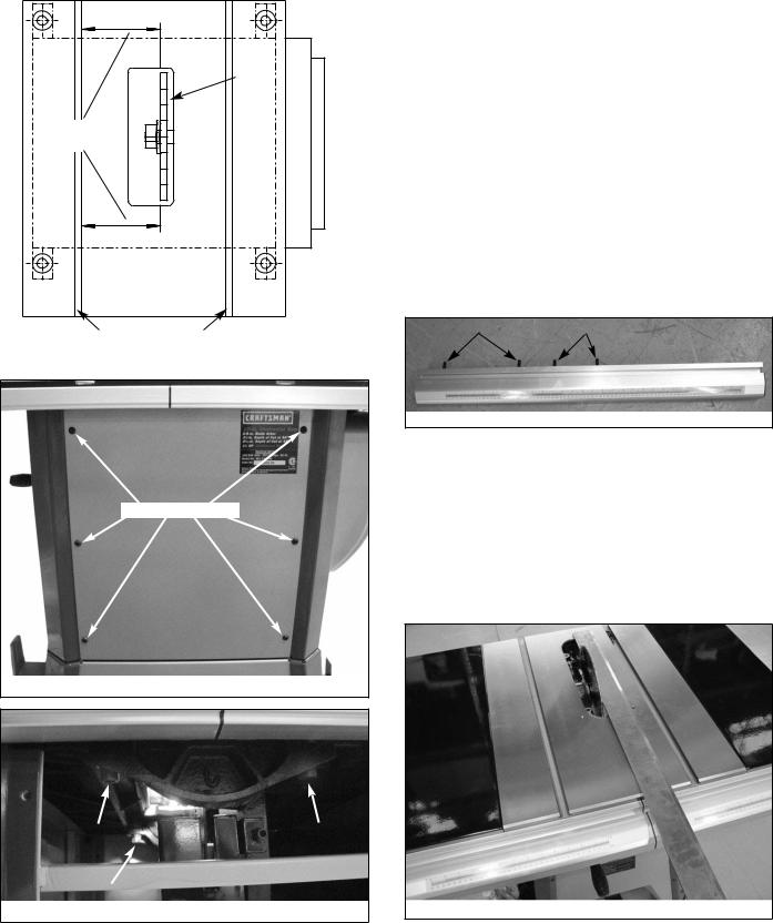
¥If an adjustment is necessary, proceed as follows: Loosen and remove the six socket pan head screws and the rear panel (see Figure 22). Loosen the four hex head bolts on the trunnion (see Figure 23) and shift trunnions until a position is found where the saw blade is parallel to the miter guage slots.
NOTE: Saw blade should also be centered within its table insert opening.
Rear
Saw
Blade
Equal
Distances
Front
Miter Gauge Slots
Figure 21 - Aligning Miter Slots to Blade
Remove Six Screws
Figure 22 - Remove Rear Panel
Figure 23 - Adjust Trunnions to Align Blade and Miter Slot
¥Tighten the hex head bolts and lock washers very securely. This procedure will set the table and blade in parallel position and prevent the trunnion from shifting.
NOTE: If you perform this adjustment, leave the back panel off to perform rear rail assembly as described in the next section.
RAIL ASSEMBLY
Refer to Figures 24-29.
Tools Required: 13mm Open end Wrench
Hardware Required: Eight M8 x 28 hex head bolts, eight M8 x 25 hex head bolts, four M8 x 20 hex head bolts, twenty M8 lock washers, twenty M8 flat washers, sixteen M8 hex nuts and four M8 acorn nuts. (Hardware bag #2).
¥Insert two M8 x 28 hex head bolts and two M8 x 25 hex head bolts into the T-slot of the right front guide rail. (The two longer bolts will attach to the table; the two shorter bolts attach to the table extension.)
¥Attach right front rail to the table and right table extension using flat washers, lock washers and hex nuts.
NOTE: Hand tighten all hardware during rail assembly. Do not completely tighten hardware until all rails are mounted.
¥Attach left front rail in the same manner. (The two longer bolts attach to the table; the two shorter bolts attach to table extension.)
NOTE: You may have to shift right rail as far right as it will go to attach left rail.
M8 x 28 Bolts |
|
|
|
M8 x 25 Bolts |
Figure 24 - Right Front Rail
¥Position rails so that rails are butted together and the joint between rails is aligned with right side of the blade. You may need a mallet to lightly tap rails together. Make sure rails are completely butted together at the joint.
¥Use a straight edge as shown to check level and flatness between right and left rail. Use a combination square as shown to make certain that both front rails are parallel to the table surface.
¥After front rails are adjusted level and flat, tighten the screws completely.
¥Secure all hardware completely.
Figure 25 - Use Straight Edge to Align Rail Joint to Blade
10

Figure 26 - Check parallelism of rails to table with combination square. Check at several locations along rail.
¥Loosen and remove six socket pan head screws and the back panel. This will allow easier attachment of the rear rails.
Figure 27
¥Install the rear rails in the same manner as the front rails and align the rail joint to the blade.
¥Replace back panel of the cabinet.
Figure 28
¥Insert M8 x 20 hex bolts through holes in bracket at each end of brace. Attach brace to the far right end of the rails by sliding hex bolts into the rail T-slots. Secure bolts in position with flat washers, lock washers and nuts.
Figure 29
ATTACH SWITCH ASSEMBLY
Refer to Figure 30.
Tools Required: 10mm Open end Wrench
Hardware Required: Two M6 x 16 hex head bolts, two M6 flat washers, two M6 lock washers and two M6 hex nuts. (Hardware bag #3).
¥From above switch assembly bracket, insert two bolts through bracket holes.
¥Loosely attach flat washer, lock washer and nut to bolts.
¥Insert bolt heads into T-slot on bottom of left front rail.
¥Slide switch assembly 6″ to 8″ from left end of rail as shown in Figure 30.
¥Fully tighten flat washers, lock washers and hex nuts to secure switch assembly in place.
Figure 30
POSITION AND ADJUST RIVING KNIFE
Refer to Figure 31.
¥Riving knife is installed on the saw. Raise the blade completely to access the riving knife.
¥Loosen the locking knob and raise the riving knife to its highest position. Riving knife has three holes for three positions. The highest position is for all thru cuts. The middle position is for rabbets and other non-thru cuts, (with guard and pawls removed). The lowest position is for dado cuts.
Locking Pin
Screw
Locking |
|
|
|
|
Knob |
|
|
|
|
|
|
Bracket |
||
Plate |
|
|||
|
|
|
|
Figure 31 - Riving Knife
11
 Loading...