


536886490
SWA/RS
owner's
manual
Model
S _A/RS
I:RRFTSMRli
DUAL STAG
C950-52021-0
10.5-H.P. 29 inch
SNOW BLOWER
CAUTION:
You must read and
understand this owner's
manual before operating
unit.
Serial No.
F-001160J SEARS CANADA INC., TORONTO, ONTARIO M5B 2B8 PrintedinU.S.A,

RULES FOR SAFE OPERATION
IMPORTANT
,_ WARNING: Always disconnect the spark plug wire and place it where it cannot make contact with _'_
spark plug to prevent accidental starting during: Preparation, Maintenance, or Storage of your
snow blower,
SAFE OPERATION PRACTICES FOR WALK-BEHIND SNOW BLOWER
DO NOT OPERATE THIS EQUIPMENT BEFORE READING THIS MANUAL
(c) Fill fuel tank outdoors with extreme care. Never fill
fuel tank indoors.
(d) Replace gasoline cap securely and wipe up spilled
Engine Exhaust, some of its constituents, and
certain vehicle components contain or emit
chemicals known to the State of California to
cause cancer and birth defects or other repro-
ductive harm.
Battery posts, terminals and related accesso-
ries contain lead and lead compounds, chemi-
cals known to the State of California to cause
cancer and birth defects or other reproductive
harm. WASH HANDS AFTER HANDLING.
TRAINING
1. Read the operating and service instructionmanual care-
fully. Be thoroughly familiar with the controls and the
proper use of the equipment. Know how to stop the unit
and disengage the controls quickly.
2. Never allow children to operate the equipment. Never al-
low adults to operate the equipment without proper in-
struction.
3. Keep the area of operation clear of all persons, particu-
larly small children and pets.
4. Exercise caution to avoid slipping or falling especially
when operating in reverse.
PREPARATION
1. Thoroughly inspect the area where the equipment isto
be used and remove all doormats, sleds, boards, wires,
and other foreign objects.
2. Disengage all clutches before starting the engine.
3. Do not operate the equipment without wearing adequate
winter outer garments. Wear footwear that wilt improve
footing on slippery surfaces.
4. Handle fuel with care; it is highly flammable.
(a) Use an approved fuel container.
(b) Never add fuel to a running engine or hot engine.
F_01160J
fuel.
.
For all units with electric starting motors use electric
starting extension cords certified CSA/UL. Use only with
a receptacle that has been installed in accordance with
local inspection authorities.
.
Adjust the auger housing height to clear gravel or
crushed rock surface.
7.
Under no circumstances should any adjustments be
made while the engine is running (except when specifi-
cally recommended by manufacturer).
8. Let engine and machine adjust to outdoor temperatures
before starting to clear snow.
9. Always wear safety glasses or eye shields during opera-
tion or while performing an adjustment or repair to protect
eyes from foreign objects that may be thrown from the
machine.
OPERATION
1. Do not put hands or feet near or under rotating parts.
Keep clear of the discharge opening at ait times.
2. Exercise extreme caution when operating on or crossing
gravel drives, walks or roads. Stay alert for hidden haz-
ards or traffic.
3. Never discharge snow onto public roads or near moving
traffic.
4. After striking a foreign object, stop the engine, remove
the wire from the spark plug, thoroughly inspect snow
blower for any damage, and repair the damage before re-
starting and operating the snow blower.
5. If the unit should start to vibrate abnormally, stop the en-
gine and check immediately for the cause. Vibration is
generally a warning of trouble.
6. Stop the engine and remove spark plug wire whenever
you leave the operating position, before unclogging the
auger/Impeller housing or discharge chute and when
making any repairs, adjustments, or inspections.
7. When cleaning, repairing, or inspecting, make certain
the augedlmpetler and all moving parts have stopped
and all controls are disengaged. Disconnect the spark
plug wire and keep the wire away from the spark plug to
prevent accidental starting.

RULES FOR SAFE OPERATION
8. Take all possible precautions when leaving the snow
blower unattended. Disengage the auger/impeller, shift
to neutral, stop engine, and remove key.
9. Do not run the engine indoors, except when starting the
engine and for transporting the snow blower in or out of
the building. Ensure the outside doors are open; exhaust
fumes are dangerous.
10. Do not clear snow across the face of slopes. Exercise ex-
treme caution when changing direction on slopes. Do not
attempt to clear steep slopes.
11. Never operate the snow blower without proper guards,
plates or other safety protective devices in place.
12. Never operate the snow blower near enclosures, auto-
mobiles, window wells, drop-offs, and the like without
proper adjustment of the snow discharge angle. Keep
children and pets away.
13. Do not overload the machine capacity by attempting to
clear snow at too fast a rate.
14. Never operate the machine at high transport speeds on
slippery surfaces. Look behind and use care when back-
ing up.
15. Never direct discharge at bystanders or allow anyone in
front of the unit.
16. Disengage power to the collector/impeller when snow
blower is transported or not in use.
MAINTENANCE AND STORAGE
1. Check shear bolts and other bolts at frequent intervalsfor
propertightness to be sure the equipment is in safe work-
ing condition.
2. Never store the machine with fuel in the tank inside a
building where ignition sources are present such as hot
water and space heaters, clothes dryers, and the like. Al-
low the engine to cool before storing in any enclosure.
3. Always refer to operator's guide instructions for impor-
tant details if the snow blower isto be stored for an ex-
tended period.
4. Maintain or replace safety and instruction labels, as nec-
essary.
5. Run the machine 2 minutes with auger clutch lever en-
gaged after blowing snow to prevent freeze-up of the au-
ger/impeller.
WARNING: Do not
use hands to un-
clog discharge
chute.
• Stop engine/motor before removing debris.
• Do not walk in front of running machine.
17. Use only attachments and accessories approved by the
manufacturer of the snow blower (such as wheel
weights, counterweights, cabs, and the like).
18. Never operate the snow blower without good visibility or
light. Always be sure of your footing and keep afirm hold
on the handles.
19. Do not over-reach. Keep proper footing and balance at
all times.
20. Do not attempt to use snow blower on a roof.
WARNING: Avoid
injury from rotating
auger- keep hands,
feet, and clothing
away.
F_01160J 3
• Do not discharge at bystanders.
• Keep people and pets a safe distance from the
machine.
• Before leaving machine, shut off engine/motor
and remove key.
OWNER'S INFORMATION
DATE PURCHASED:
MODEL NO:
SERIAL NO:
STORE WHERE PURCHASED:
ADDRESS:
CITY: PROVINCE:
TELEPHONE :
_Record this information about your unit so that you will
be able to provide it in case of loss or theft,
MAINTENANCE AGREEMENT
The Craftsman Warranty, plus a Maintenance Agree-
ment, provide maximum value for Sears products. Con-
tact your nearest Sears store for details.
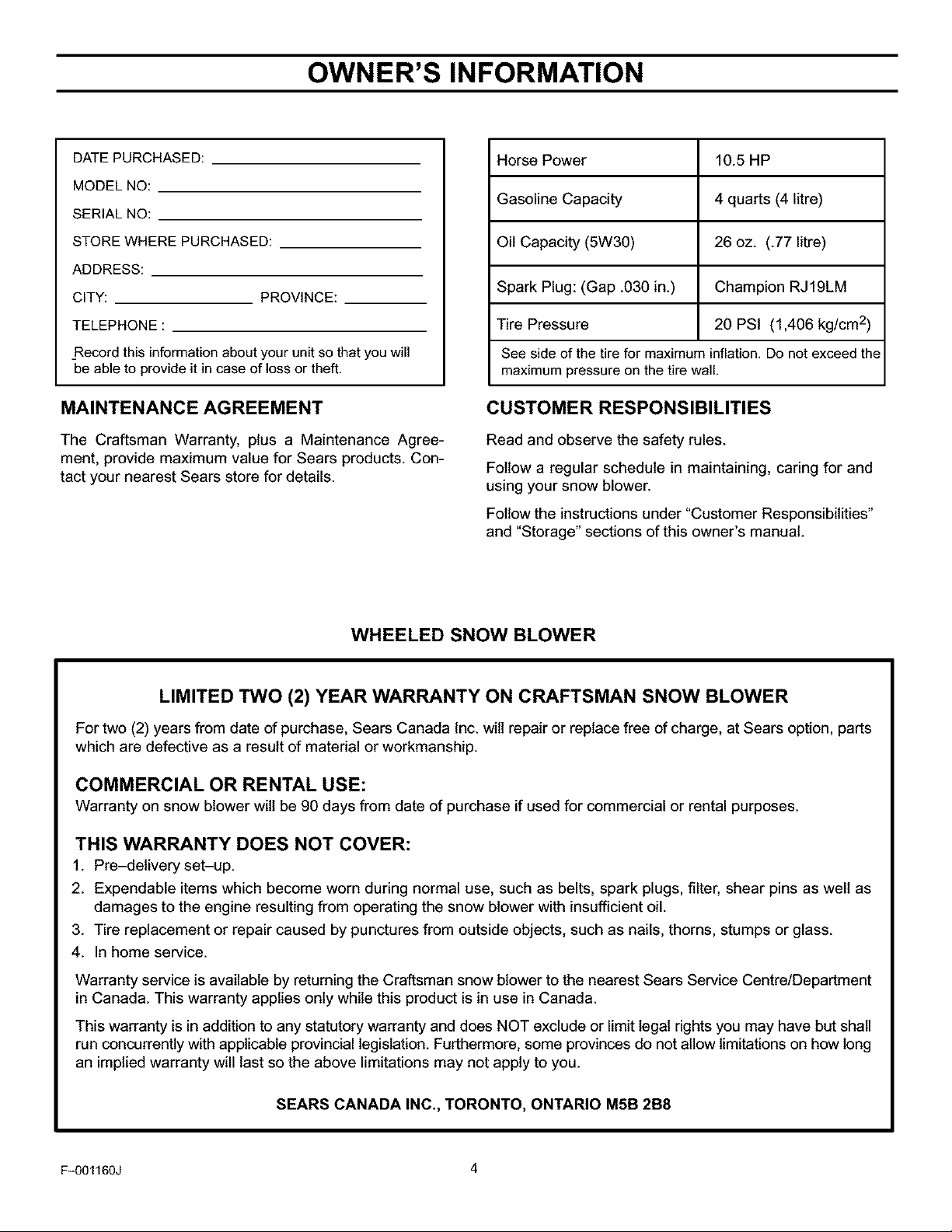
Horse Power 10.5 HP
Gasoline Capacity 4 quarts (4 litre)
Oil Capacity (5W30) 26 oz. (.77 litre)
Spark Plug: (Gap .030 in.) Champion RJ19LM
Tire Pressure 20 PSI (1,406 kg/cm 2)
See side of the tire for maximum inflation. Do not exceed the
maximum pressure on the tire wall.
CUSTOMER RESPONSIBILITIES
Read and observe the safety rules.
Follow a regular schedule in maintaining, caring for and
using your snow blower.
Follow the instructions under "Customer Responsibilities"
and "Storage" sections of this owner's manual.
WHEELED SNOW BLOWER
LIMITED TWO (2) YEAR WARRANTY ON CRAFTSMAN SNOW BLOWER
For two (2) years from date of purchase, Sears Canada Inc. will repair or replace free of charge, at Sears option, parts
which are defective as a result of material or workmanship.
COMMERCIAL OR RENTAL USE:
Warranty on snow blower will be 90 days from date of purchase if used for commercial or rental purposes.
THIS WARRANTY DOES NOT COVER:
1. Pre-detivery set-up.
2. Expendable items which become worn during normal use, such as belts, spark plugs, filter, shear pins as well as
damages to the engine resulting from operating the snow blower with insufficient oil.
3. Tire replacement or repair caused by punctures from outside objects, such as nails, thorns, stumps or glass.
4. In home service.
Warranty service is available by returning the Craftsman snow blower to the nearest Sears Service Centre/Department
in Canada. This warranty applies only while this product is in use in Canada.
This warranty is in addition to any statutory warranty and does NOT exclude or limit legal rights you may have but shall
run concurrently with applicable provincial legislation. Furthermore, some provinces do not allow limitations on how long
an implied warranty will last so the above limitations may not apply to you.
SEARS CANADA INC., TORONTO, ONTARIO M5B 2B8
Fq)01160J 4
TABLE OF CONTENTS
RULES FOR SAFE OPERATION .................... 2
OWNER'S INFORMATION ......................... 4
ASSEMBLY ...................................... 6
TOOLS REQUIRED FOR ASSEMBLY ............. 6
CONTENTS OF SHIPPING CARTON .............. 6
PARTS BAGS CONTENTS: ...................... 6
UNPACKING ................................... 7
UPPER HANDLE AND CRANK ASSEMBLY ........ 8
CONNECT CONTROL CABLE SPRINGS .......... 8
SPEED SELECT LEVER ......................... 9
SNOW CHUTE ASSEMBLY ...................... 9
HEADLIGHT ASSEMBLY ....................... 10
OPERATION .................................... 11
SNOW BLOWER .............................. 20
AS REQUIRED ................................ 20
LUBRICATION AT STORAGE ................... 20
LUBRICATION - EVERY 10 HOURS ............. 20
LUBRICATION - EVERY 25 HOURS ............. 21
ENGINE ...................................... 22
ADJUSTMENT/REPAIR ........................... 23
AUGER HOUSING HEIGHT ADJUSTMENT ....... 23
TO ADJUST SCRAPER BAR .................... 23
TO ADJUST SKID HEIGHT ..................... 23
BELT ADJUSTMENT ........................... 24
TRACTION DRIVE BELT ....................... 24
AUGER DRIVE BELT .......................... 24
ENGINE AND SNOW BLOWER OPERATING
CONTROLS ................................ 11
WHEEL LOCK OUT PIN ........................ 13
BEFORE STARTING ENGINE ................... 14
FILL OIL ...................................... 14
FILL GAS ..................................... 14
TO START ENGINE ............................ 15
COLD ENGINE START (RECOIL STARTER) ...... 15
WARM ENGINE START (RECOIL STARTER) ...... 15
USE OF ELECTRIC STARTER .................. 16
COLD ENGINE START (ELECTRIC STARTER) .... 16
WARM ENGINE START (ELECTRIC STARTER) ... 17
OPERATING TIPS ............................. 18
BELT REPLACEMENT .......................... 25
AUGER DRIVE BELT .......................... 25
TRACTION DRIVE BELT ....................... 25
BELT GUIDE ADJUSTMENT .................... 26
CABLE ADJUSTMENT -
TRACTION DRIVE AND AUGER DRIVE ........ 26
FRICTION WHEEL ADJUSTMENT ............... 27
FRICTION WHEEL REPLACEMENT ............. 28
AUGER SHEAR BOLT REPLACEMENT .......... 29
SPARK PLUG ADJUSTMENT ................... 29
STORAGE ...................................... 30
TROUBLE SHOOTING CHART .................... 31
REPAIR PARTS .................................. 32
SERVICE RECOMMENDATIONS .................. 19
CUSTOMER RESPONSIBILITIES .................. 20
F_01160J 5
PARTS ORDERING SERVICE ..................... 53
ORDER REPAIR PARTS .......................... 54
ASSEMBLY
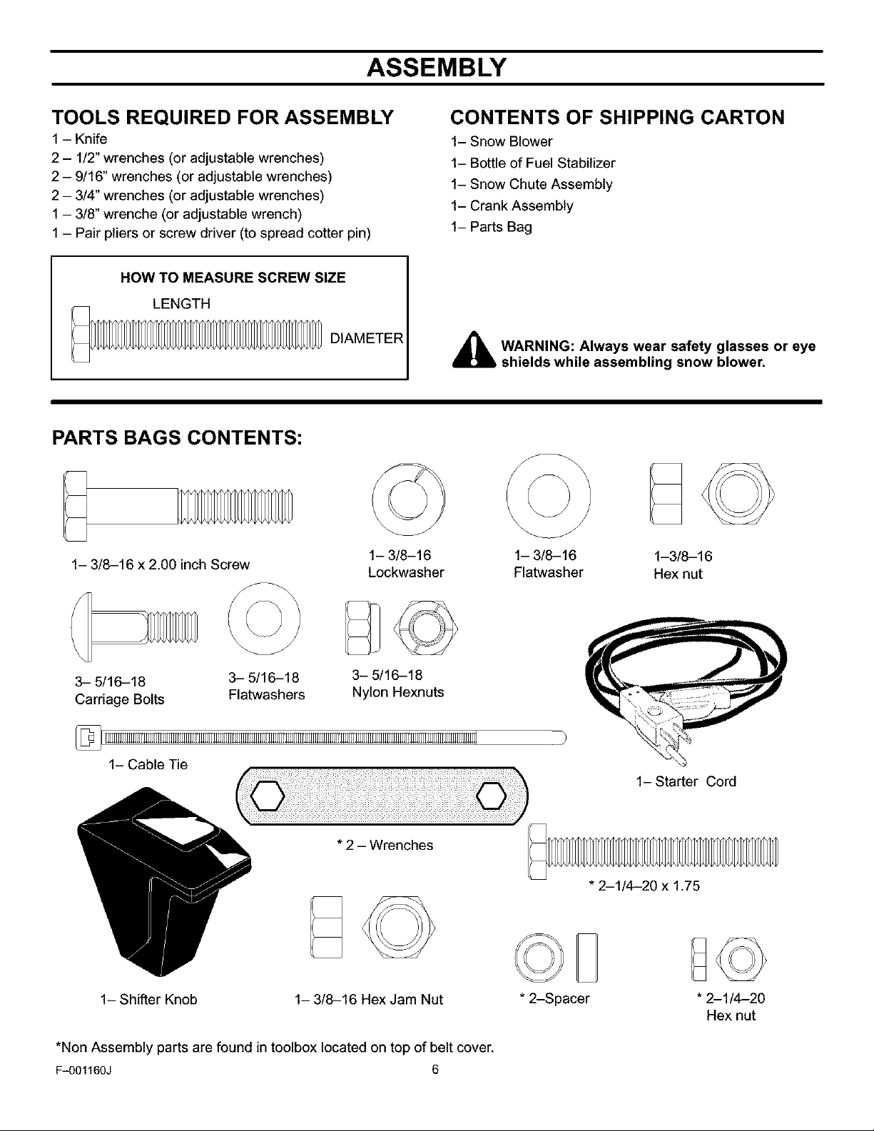
TOOLS REQUIRED FOR ASSEMBLY
1 - Knife
2 - 1/2" wrenches (or adjustable wrenches)
2 - 9/16" wrenches (or adjustable wrenches)
2 - 3/4" wrenches (or adjustable wrenches)
1 - 3/8" wrenche (or adjustable wrench)
1 - Pair pliers or screw driver (to spread cotter pin)
HOW TO MEASURE SCREW SIZE
LENGTH
DIAMETER
PARTS BAGS CONTENTS:
CONTENTS OF SHIPPING CARTON
1- Snow Blower
1- Bottle of Fuel Stabilizer
1- Snow Chute Assembly
1- Crank Assembly
1- Parts Bag
4_lb WARNING: Always wear safety glasses or eye
shields while assembling snow blower.
\
1- 3/8-16 x 2.00 inch Screw
\
3- 5/16-18 3- 5/16-18
Carriage Bolts Flatwashers
1- Cable Tie
1- 3/8-16
Lockwasher
3- 5/16-18
Nylon Hexnuts
* 2 - Wrenches
1- 3/8-16 1-3/8-16
Flatwasher Hex nut
1- Starter Cord
* 2-1/4-20 x 1.75
1- Shifter Knob 1- 3/8-16 Hex Jam Nut
*Non Assembly parts are found in toolbox located on top of belt cover.
F_01160J 6
* 2-Spacer
* 2-1/4-20
Hex nut
ASSEMBLY
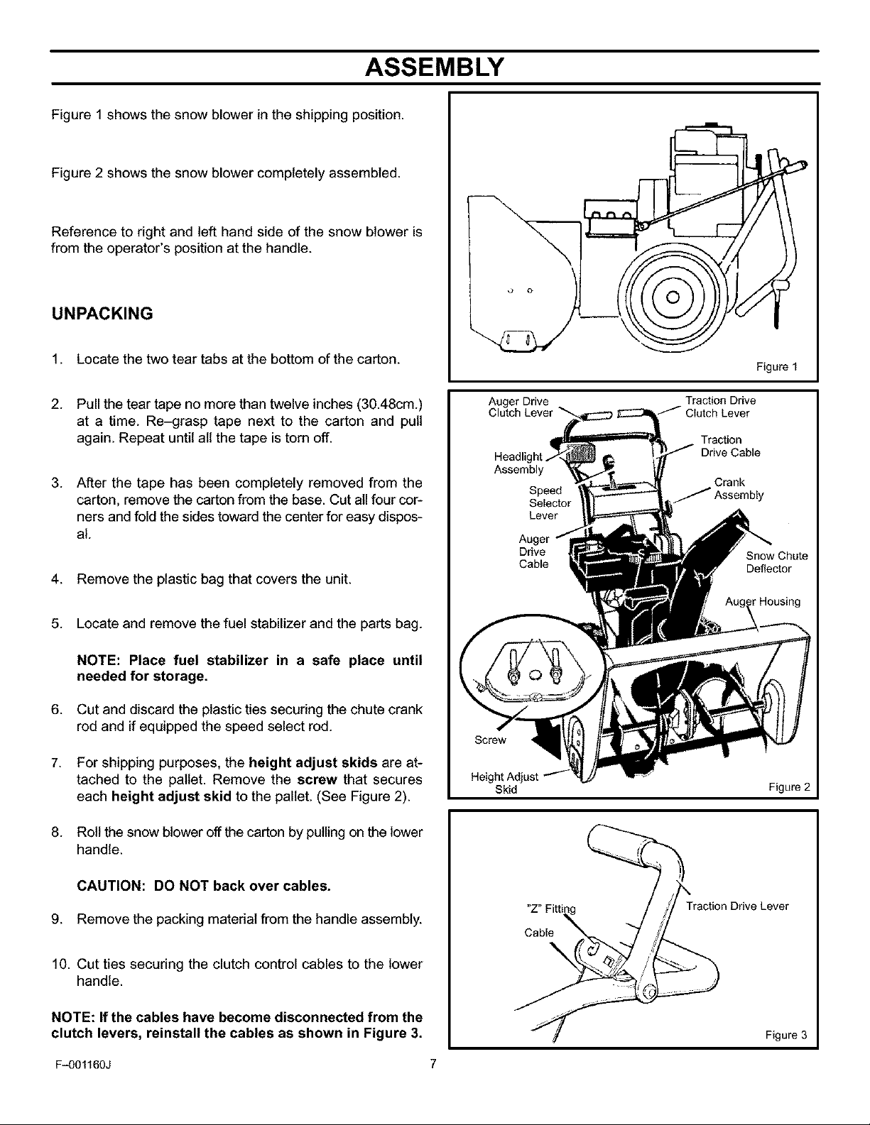
Figure 1 shows the snow blower in the shipping position.
Figure 2 shows the snow blower completely assembled.
Reference to right and left hand side of the snow blower is
from the operator's position at the handle.
UNPACKING
1. Locate the two tear tabs at the bottom of the carton.
2. Pull the tear tape no more than twelve inches (30.48cm.)
at a time. Re-grasp tape next to the carton and pull
again. Repeat until all the tape is torn off.
3. After the tape has been completely removed from the
carton, remove the carton from the base. Cut all four cor-
ners and fold the sides toward the center for easy dispos-
al.
4. Remove the plastic bag that covers the unit.
5. Locate and remove the fuel stabilizer and the parts bag.
NOTE: Place fuel stabilizer in a safe place until
needed for storage.
6. Cut and discard the plastic ties securing the chute crank
rod and if equipped the speed select rod.
7. For shipping purposes, the height adjust skids are at-
tached to the pallet. Remove the screw that secures
each height adjust skid to the pallet. (See Figure 2).
Auger Drive
Clutch Lever
Headl
Assembly
Speed
Selector
Lever
Drive
Cable
Skid
Figure 1
Traction Drive
Traction
Drive Cable
Crank
Snow Chute
Deflector
_rHousing
Figure 2
8. Roll the snow blower off the carton by pulling on the lower
handle.
CAUTION: DO NOT back over cables.
9. Remove the packing material from the handle assembly.
10. Cut ties securing the clutch control cables to the lower
handle.
NOTE: If the cables have become disconnected from the
clutch levers, reinstall the cables as shown in Figure 3.
Fq)01160J 7
"Z" Fit
Cable
Traction Drive Lever
Figure 3
ASSEMBLY
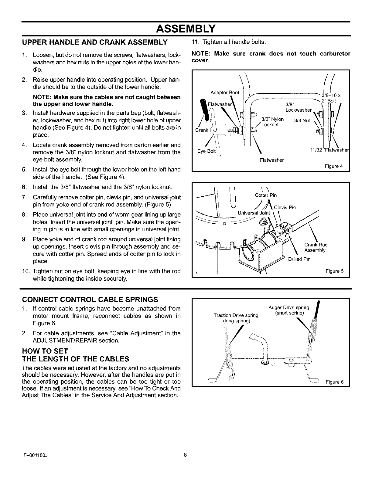
UPPER HANDLE AND CRANK ASSEMBLY 11. Tightenall handle bolts.
1. Loosen, but do not remove the screws, flatwashers, lock-
washers and hex nuts inthe upper holes of the lower han-
dle.
2. Raise upper handle into operating position. Upper han-
dle should be to the outside of the lower handle.
NOTE: Make sure the cables are not caught between
the upper and lower handle.
3. Install hardware supplied inthe parts bag (bolt, flatwash-
er, Iockwasher, and hex nut) into right lower hole of upper
handle (See Figure 4). Do not tighten until all bolts are in
place.
4. Locate crank assembly removed from carton eadier and
remove the 3/8" nylon Iocknut and flatwasher from the
eye bolt assembly.
5. Install the eye bolt through the lower hole on the left hand
side of the handle. (See Figure 4).
6. Install the 3/8" flatwasher and the 3/8" nylon locknut.
7. Carefully remove cotter pin, clevis pin, and universal joint
pin from yoke end of crank rod assembly. (Figure 5)
8. Place universal joint into end of worm gear lining up large
holes. Insert the universal joint pin. Make sure the open-
ing in pin is in line with small openings in universal joint.
9. Place yoke end of crank rod around universal joint lining
up openings. Insert clevis pin through assembly and se-
cure with cotter pin. Spread ends of cotter pin to lock in
place.
10. Tighten nut on eye bolt, keeping eye in line with the rod
while tightening the inside securely.
NOTE: Make sure crank does not touch carburetor
cover.
/
Eye Bolt
Adap_rBo_
3/8" Nylon
_JLocknut
Flatwasher
3/8" /
3/8Nut
Lockwasher_ ID
Drilled Pin
_" 3/8-16 x
"", 2" Bolt
11/32 "Flatwasher
Figure 4
Crank Rod
Assembly
Figure 5
\
CONNECT CONTROL CABLE SPRINGS
1. If control cable springs have become unattached from
motor mount frame, reconnect cables as shown in
Figure 6.
2. For cable adjustments, see "Cable Adjustment" in the
ADJUSTMENT/REPAIR section.
HOW TO SET
THE LENGTH OF THE CABLES
The cables were adjusted at the factory and no adjustments
should be necessary. However, after the handles are put in
the operating position, the cables can be too tight or too
loose. If an adjustment is necessary, see "How To Check And
Adjust The Cables" in the Service And Adjustment section.
F_)O1160J 8
Figure 6
ASSEMBLY
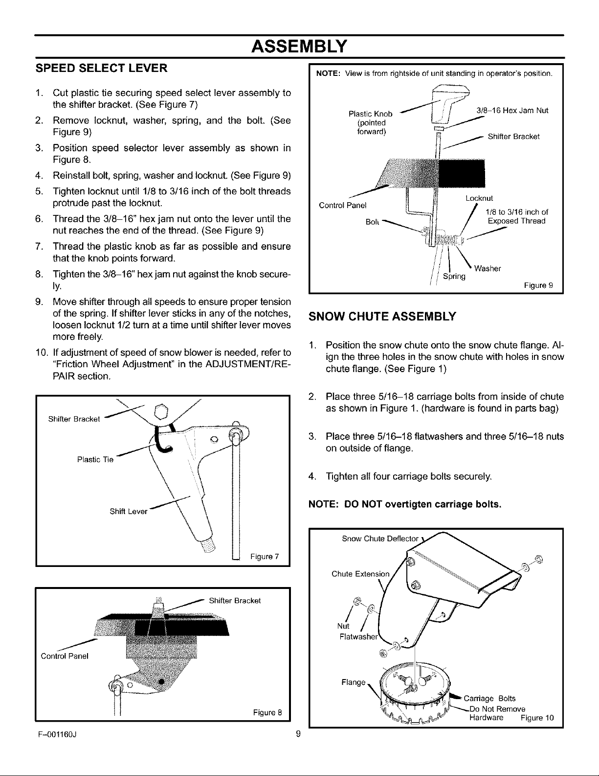
SPEED SELECT LEVER
1. Cut plastic tie securing speed select lever assembly to
the shifter bracket. (See Figure 7)
2. Remove locknut, washer, spring, and the bolt. (See
Figure 9)
3. Position speed selector lever assembly as shown in
Figure 8.
4. Reinstall bolt, spring, washer and locknut. (See Figure 9)
5. Tighten Iocknut until 1/8 to 3/16 inch of the bolt threads
protrude past the tocknut.
6. Thread the 3/8-16" hexjam nut onto the lever until the
nut reaches the end of the thread. (See Figure 9)
7. Thread the plastic knob as far as possible and ensure
that the knob points forward.
8. Tighten the 3/8-16" hex jam nut against the knob secure-
ly.
9. Move shifter through ait speeds to ensure proper tension
of the spring. If shifter lever sticks in any of the notches,
loosen locknut 1/2 turn at a time until shifter lever moves
more freely.
10. If adjustment of speed of snow blower is needed, refer to
"Friction Wheel Adjustment" in the ADJUSTMENT/RE-
PAIR section.
NOTE: View is from rightside of unit standing in operator's position.
stic oo
forward) Shifter Bracket
Control Panel
SNOW CHUTE ASSEMBLY
1. Position the snow chute onto the snow chute flange. Al-
ign the three holes in the snow chute with holes in snow
chute flange. (See Figure 1)
Locknut
1/8to3/16inchof
Exposed Thread
Figure 9
Shifter Bracket
Plastic Tie
Control Panel
Shift Lever
2. Place three 5/16-18 carriage bolts from inside of chute
as shown in Figure 1. (hardware is found in parts bag)
3. Place three 5/16-18 flatwashers and three 5/16-18 nuts
on outside of flange.
4. Tighten all four carriage bolts securely.
NOTE: DO NOT overtigten carriage bolts.
Snow Chute Deflector
Figure 7
Chute Extension
Shifter Bracket
Nut
Figure 8
Fq)O1160J 9
Flange_
Bolts
Not Remove
Hardware Figure 10
ASSEMBLY
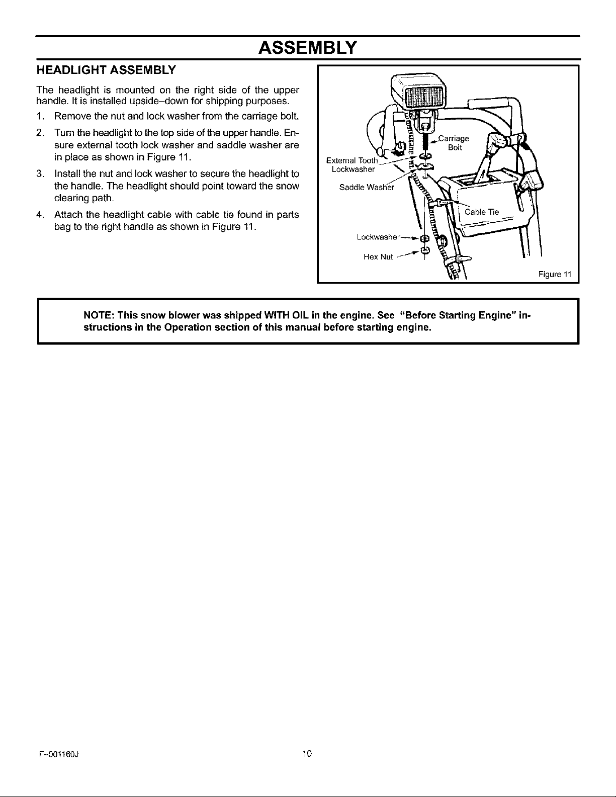
HEADLIGHT ASSEMBLY
The headlight is mounted on the right side of the upper
handle. It is installed upside-down for shipping purposes.
1. Remove the nut and lock washer from the carriage bolt.
2. Turn the headlight to the top side of the upper handle. En-
sure external tooth lock washer and saddle washer are
in place as shown in Figure 11.
3. Install the nut and lock washer to secure the headlight to
the handle. The headlight should point toward the snow
clearing path.
4. Attach the headlight cable with cable tie found in parts
bag to the right handle as shown in Figure 11.
NOTE: This snow blower was shipped WITH OIL in the engine. See "Before Starting Engine" in-
I
structions in the Operation section of this manual before starting engine,
External Toot
Lockwasher
Lockwasher_-_
Hex Nut
Figure 11
F_01160J 10
OPERATION
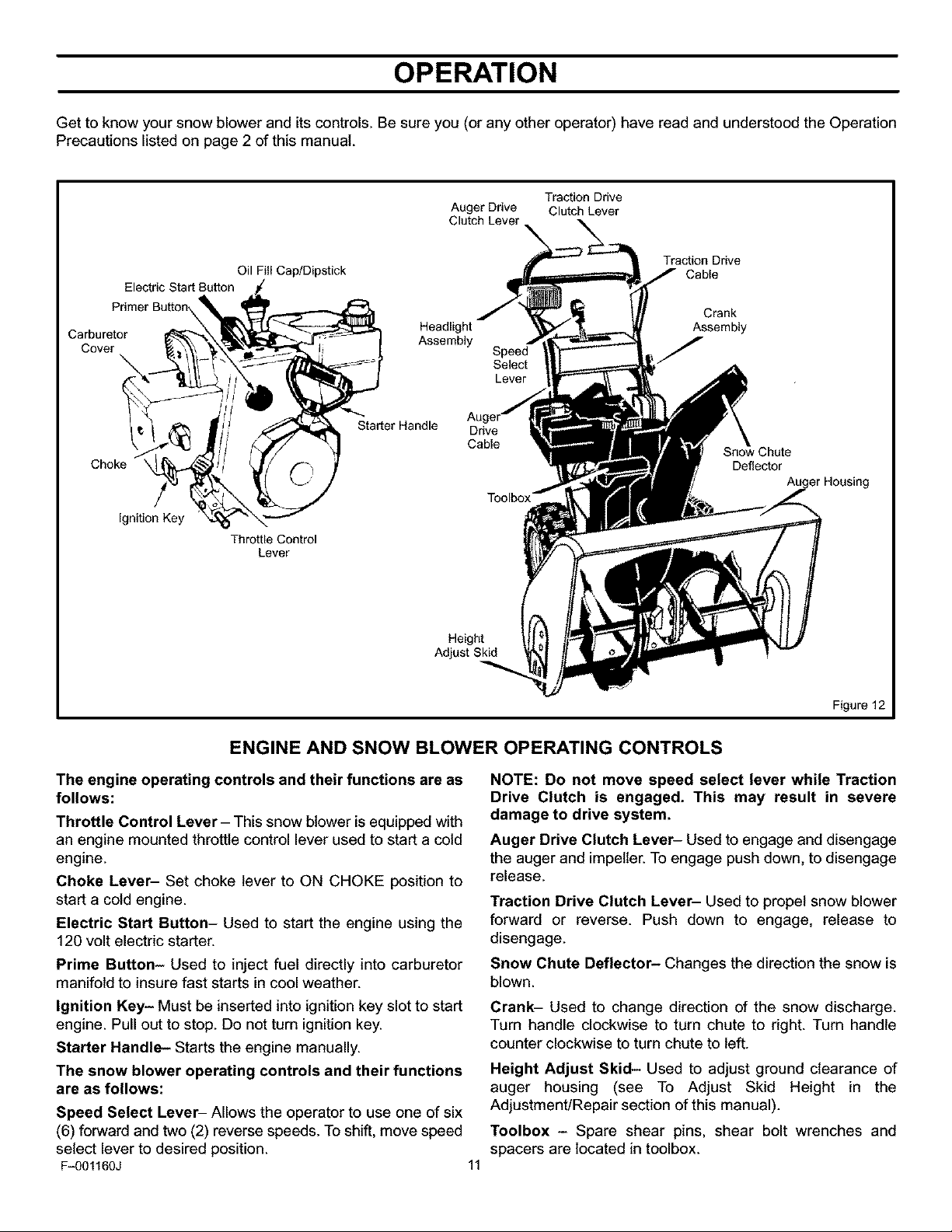
Get to know your snow blower and itscontrols. Be sure you (or any other operator) have read and understood the Operation
Precautions listed on page 2 of this manual.
Carburetor
Cover
Choke \
Electric Start Button
Primer Button
Ignition Key
Oil Fill Cap/Dipstick
Throttle Control
Lever
Headlight
Assembly
Starter Handle
Auger Ddve Clutch Lever
Clutch Lever
Speed
Select
Lever
Drive
Cable
Height
Adjust Skid
Traction Drive
Traction Drive
Cable
Crank
Assembly
Deflector
Auger Housing
ENGINE AND SNOW BLOWER OPERATING CONTROLS
The engine operating controls and their functions are as
follows:
Throttle Control Lever - This snow blower is equipped with
an engine mounted throttle control lever used to start a cold
engine.
Choke Lever- Set choke lever to ON CHOKE position to
start a cold engine.
Electric Start Button- Used to start the engine using the
120 volt electric starter.
Prime Button- Used to inject fuel directly into carburetor
manifold to insure fast starts in cool weather.
Ignition Key- Must be inserted into ignition key slot to start
engine. Pull out to stop. Do not turn ignition key.
Starter Handle- Starts the engine manually.
The snow blower operating controls and their functions
are as follows:
Speed Select Lever- Allows the operator to use one of six
(6) forward and two (2) reverse speeds. To shift, move speed
select lever to desired position.
Fq)01160J 11
Figure 12
NOTE: Do not move speed select lever while Traction
Drive Clutch is engaged. This may result in severe
damage to drive system.
Auger Drive Clutch Lever- Used to engage and disengage
the auger and impeller. To engage push down, to disengage
release.
Traction Drive Clutch Lever- Used to propel snow blower
forward or reverse. Push down to engage, release to
disengage.
Snow Chute Deflector- Changes the direction the snow is
blown.
Crank- Used to change direction of the snow discharge.
Turn handle clockwise to turn chute to right. Turn handle
counter clockwise to turn chute to left.
Height Adjust Skid- Used to adjust ground clearance of
auger housing (see To Adjust Skid Height in the
Adjustment/Repair section of this manual).
Toolbox - Spare shear pins, shear bolt wrenches and
spacers are located in toolbox.
OPERATION
_ The operation of any snow blower can result in foreign objects being thrown into the eyes,which can
result in severe eye damage. Always wear safety glasses or eye shields before beginning snow blower
Operation. We recommend standard safety glasses or Wide Vision Safety Mask for over spectacles.
SNOW BLOWER OPERATION
The most effective use of the snow blower will be established
by experience, taking into consideration the terrain, wind
conditions and building location which will determine the
direction of the discharge chute.
NOTE: Do not blow snow towards a building as hidden
objects could be blown with sufficient force to cause
damage.
1. Start the engine as described in section "To Start Engine"
(see Figure 15).
2. Adjust snow chute deflector. Loosen wing nut on the side
of the snow chute and raise chute deflector for more dis-
tance. Tighten wing nut. (see Figure 14).
3. Using crank, position the discharge chute to discharge
snow with the wind.
4. Select proper speed for snow conditions as outlined be-
low and set speed select lever to desired position.
NOTE: Always release traction drive clutch lever
before moving speed select lever.
_lb WARNING: Read Owner's Manual before oper-
Never operate the snow blower without all guards, cov-
ers, and shields in place.
Never direct discharge towards windows or allow by-
standers near machine while engine is running.
Stop the engine whenever leaving the operating posi-
tion.
Disconnect spark plug before unclogging the impeller
housing or the discharge chute and before making re-
pairs or adjustments.
When leaving the machine, remove the ignition key.
To reduce the risk of fire, keep the machine clean and
free from spilled gas, oil and debris.
ating machine. This machine can be dangerous
if used carelessly.
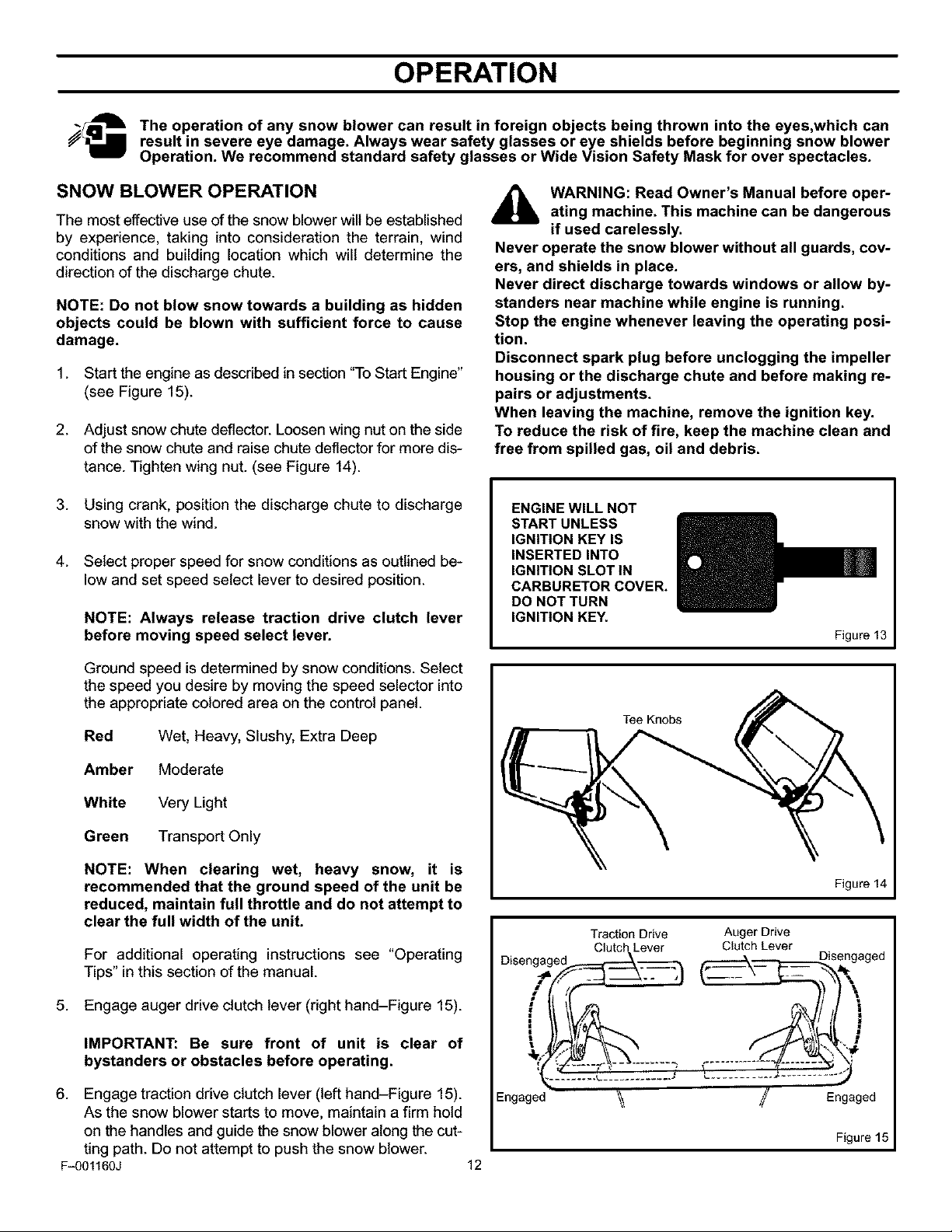
ENGINE WILL NOT
START UNLESS
IGNITION KEY IS
INSERTED INTO
IGNITION SLOT IN
CARBURETOR COVER.
DO NOT TURN
IGNITION KEY.
Figure 13
Ground speed is determined by snow conditions. Select
the speed you desire by moving the speed selector into
the appropriate colored area on the control panel.
Red Wet, Heavy, Slushy, Extra Deep
Amber Moderate
White Very Light
Green Transport Only
NOTE: When clearing wet, heavy snow, it is
recommended that the ground speed of the unit be
reduced, maintain full throttle and do not attempt to
clear the full width of the unit.
For additional operating instructions see "Operating
Tips" in this section of the manual.
5. Engage auger drive clutch lever (right hand-Figure 15).
IMPORTANT: Be sure front of unit is clear of
bystanders or obstacles before operating.
6. Engage traction drive clutch lever (left hand-Figure 15).
As the snow blower starts to move, maintain a firm hold
on the handles and guide the snow blower along the cut-
ting path. Do not attempt to push the snow blower.
F_01160J 12
Traction Drive
Dise ngaged_____---_
#L lf
Engaged
Tee Knobs
Clutch Lever
Figure 14
Auger Drive
Clutch Lever
. Disengaged
{- _....... -_'_._'_.4
_/ Engaged
Figure 15

OPERATION
7. To stop forward motion, release traction drive clutch lever
(left hand - Figure 15).
8. To stop the auger, release auger drive clutch lever (right
hand - Figure 15).
9. To move the snow blower backwards, move speed select
lever into first or second reverse and engage traction
drive clutch lever (left hand). To stop, release traction
drive clutch lever.
WHEEL LOCK OUT PIN
1. The left hand wheel is secured to the axle with a klick pin.
This unit was shipped with this klick pin inthe locked posi-
tion. (Figure 16).
WARNING: Never run engine indoors or in an
enclosed, poor ventilated area. Engine exhaust
contains CARBON MONOXIDE, an OR-
DERLESS and DEADLY GAS.
Keep hands, feet, hair and loose clothing away from
any moving parts on engine and snow blower.
Temperature of muffler and nearby areas can exceed
150 ° F (66° C). Avoid these areas.
DO NOT allow children or young teenagers to operate
or be near snow blower while it is operating.
Locked
Position
Figure 16
2. For ease of maneuverability when lighter conditions pre-
vail, remove klick pin from wheel locked position and in-
sert into single wheel drive (unlocked) position
(Figure 17). Make sure that the klick pin is in the single
wheel drive position of the axle only and not through the
locked position.
Single Wheel
Drive Position
(Unlocked)
Figure 17
NOTE: Check tire pressure (20 pounds). See side of tire
for maximum inflation. Do not exceed listed maximum
pressure.
_lb WARNING: Do not attempt to remove any item
that may become lodged in auger without tak-
ing the following precautions:
• Release auger and drive clutch levers.
• Move throttle lever to STOP position.
• Remove the ignition key.
• Disconnect the spark plug wire.
• Do not put your hands in the auger or
discharge chute. Use a pry bar.
F_01160J 13
OPERATION
BEFORE STARTING ENGINE
Check the oil
NOTE: The engine was shipped from the factory filled
with oil. Check the level of the oil. Add oil as needed.
1. Make sure the unit is level.
2. Remove the oil fitl cap/dipstick. Check the oil.
NOTE: Do not check the level of the oil while the
engine runs.
3. If necessary, add oil until the oil reaches the FULL mark
on the oil fill/cap dipstick (see Figure 18). Do not add too
much oil.
NOTE: For extreme cold operating conditions of O°F
(-18 ° C) and below, use a synthetic OW3O motor oil for
easier starting.
NOTE: S.A.E. 5W30 motor oil may be used to make
starting easier in areas where the temperature is 20 ° F.
(-7 ° C) to O°F (-18 ° C).
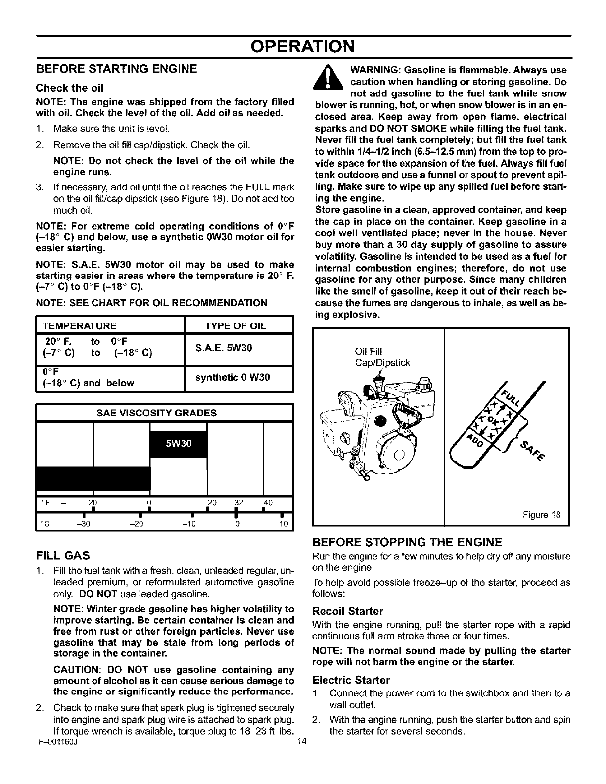
NOTE: SEE CHART FOR OIL RECOMMENDATION
TEMPERATURE TYPE OF OIL
20 ° F. to O°F
(-7 ° C) to (-18 ° C) S.A.E. 5W30
WARNING: Gasoline is flammable. Always use
caution when handling or storing gasoline. Do
not add gasoline to the fuel tank while snow
blower is running, hot, or when snow blower is in an en-
closed area. Keep away from open flame, electrical
sparks and DO NOT SMOKE while filling the fuel tank.
Never fill the fuel tank completely; but fill the fuel tank
to within 1/4-1/2 inch (6.5-12.5 mm) from the top to pro-
vide space for the expansion of the fuel. Always fill fuel
tank outdoors and use a funnel or spout to prevent spil-
ling. Make sure to wipe up any spilled fuel before start-
ing the engine.
Store gasoline in a clean, approved container, and keep
the cap in place on the container. Keep gasoline in a
cool well ventilated place; never in the house. Never
buy more than a 30 day supply of gasoline to assure
volatility. Gasoline Is intended to be used as a fuel for
internal combustion engines; therefore, do not use
gasoline for any other purpose. Since many children
like the smell of gasoline, keep it out of their reach be-
cause the fumes are dangerous to inhale, as well as be-
ing explosive.
Oil Fill
0OF
(-18 ° C) and below synthetic O W3O
SAE VISCOSITY GRADES
°F 20 0 20 32 40
°C -30 -20 -10 0 10
I I I I I
I • • I •
FILL GAS
1. Fill the fuel tank with a fresh, clean, unleaded regular, un-
leaded premium, or reformulated automotive gasoline
only. DO NOT use leaded gasoline.
NOTE: Winter grade gasoline has higher volatility to
improve starting. Be certain container is clean and
free from rust or other foreign particles. Never use
gasoline that may be stale from long periods of
storage in the container.
CAUTION: DO NOT use gasoline containing any
amount of alcohol as it can cause serious damage to
the engine or significantly reduce the performance.
2. Check to make sure that spark plug istightened securely
into engine and spark plug wire is attached to spark plug.
If torque wrench is available, torque plug to 18-23 ft-lbs.
Fq)01160J 14
%
Figure 18
BEFORE STOPPING THE ENGINE
Run the engine for a few minutes to help dry off any moisture
on the engine.
To help avoid possiblefreeze-up of the starter, proceed as
follows:
Recoil Starter
With the engine running, pull the starter rope with a rapid
continuousfull arm stroke three or four times.
NOTE: The normal sound made by pulling the starter
rope will not harm the engine or the starter.
Electric Starter
1. Connect the power cord to the switchbox and then to a
walt outlet.
2. With the engine running, push the starter button and spin
the starter for several seconds.
OPERATION
NOTE: The normal sound made by spinning the
starter will not harm the engine or the starter.
3. Disconnect the power cord from the receptacle first and
then from the switchbox.
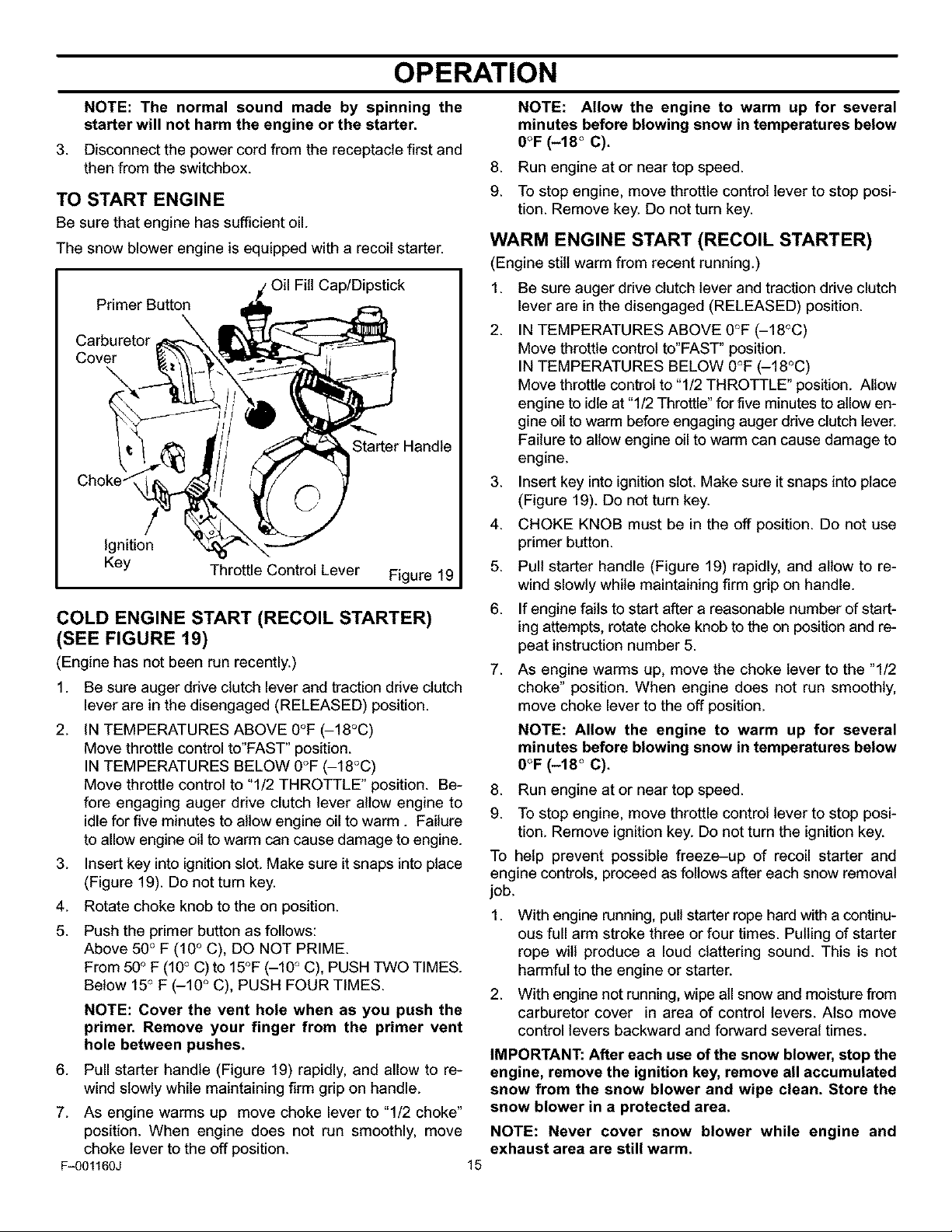
TO START ENGINE
Be sure that engine has sufficientoil.
The snow blower engine is equipped with a recoil starter.
Cap/Dipstick
Primer Button
Carburetor
Cover
Starter Handle
Ignition
Key
Throttle Control Lever Figure 19
COLD ENGINE START (RECOIL STARTER)
(SEE FIGURE 19)
(Engine has not been run recently.)
1. Be sure auger drive clutch lever and traction drive clutch
lever are in the disengaged (RELEASED) position.
2. iN TEMPERATURES ABOVE 0°F (-18°C)
Move throttle control to'FAST" position.
IN TEMPERATURES BELOW 0°F (-18°C)
Move throttle control to "1/2 THROTTLE" position. Be-
fore engaging auger drive clutch lever allow engine to
idle for five minutes to allow engine oil to warm. Failure
to allow engine oil to warm can cause damage to engine.
3. Insert key into ignitionslot. Make sure it snaps into place
(Figure 19). Do not turn key.
4. Rotate choke knob to the on position.
5. Push the primer button as follows:
Above 50° F (10 ° C), DO NOT PRIME.
From 50° F (10° C) to 15°F (-10 ° C), PUSH TWO TIMES.
Below 15° F (-10 ° C), PUSH FOUR TIMES.
NOTE: Cover the vent hole when as you push the
primer. Remove your finger from the primer vent
hole between pushes.
6. Pull starter handle (Figure 19) rapidly, and allow to re-
wind slowly while maintaining firm grip on handle.
7. As engine warms up move choke lever to "1/2 choke"
position. When engine does not run smoothly, move
choke lever to the off position.
F_01160J 15
NOTE: Allow the engine to warm up for several
minutes before blowing snow in temperatures below
O°F (-18 ° C).
.
Run engine at or near top speed.
9.
To stop engine, move throttle control lever to stop posi-
tion. Remove key. Do not turn key.
WARM ENGINE START (RECOIL STARTER)
(Engine still warm from recent running.)
1. Be sure auger drive clutch lever and traction drive clutch
lever are in the disengaged (RELEASED) position.
2.
IN TEMPERATURES ABOVE 0°F (-18°C)
Move throttle control to'FAST" position.
IN TEMPERATURES BELOW 0°F (-18°C)
Move throttle control to "1/2 THROTTLE" position. Allow
engine to idle at "1/2 Throttle" for five minutes to allow en-
gine oil to warm before engaging auger drive clutch lever.
Failure to allow engine oil to warm can cause damage to
engine.
3.
Insert key into ignitionslot. Make sure it snaps into place
(Figure 19). Do not turn key.
4.
CHOKE KNOB must be in the off position. Do not use
primer button.
5.
Pull starter handle (Figure 19) rapidly, and allow to re-
wind slowly while maintaining firm grip on handle.
6.
If engine fails to start after a reasonable number of start-
ing attempts, rotate choke knob to the on position and re-
peat instruction number 5.
7.
As engine warms up, move the choke lever to the "1/2
choke" position. When engine does not run smoothly,
move choke lever to the off position.
NOTE: Allow the engine to warm up for several
minutes before blowing snow in temperatures below
O°F (-18 ° C).
.
Run engine at or near top speed.
9.
To stop engine, move throttle control lever to stop posi-
tion. Remove ignition key. Do not turn the ignition key.
To help prevent possible freeze-up of recoil starter and
engine controls, proceed as follows after each snow removal
job.
1.
With engine running,pull starter rope hard with a continu-
ous full arm stroke three or four times. Pulling of starter
rope will produce a loud clattering sound. This is not
harmful to the engine or starter.
2. With engine not running, wipe all snow and moisture from
carburetor cover in area of control levers. Also move
control levers backward and forward several times.
IMPORTANT: After each use of the snow blower, stop the
engine, remove the ignition key, remove all accumulated
snow from the snow blower and wipe clean. Store the
snow blower in a protected area.
NOTE: Never cover snow blower while engine and
exhaust area are still warm.
USE OF ELECTRIC STARTER
OPERATION
On models so equipped
,_ WARNING: The electric starter is equipped with
a three-wire power cord and plug designed to
operate on 120 volt AC house hold current. The
power cord must be properly grounded at all times to
avoid the possibility of electric shock which can cause
injury to the operator. Follow all instructions carefully
as set forth below:
Make sure your house has a three-wire grounded sys-
tem. If you are not sure, ask a licensed electrician. If
your house does not have a three-wire grounded sys-
tem, do not use this electric starter under any condi-
tion.
If your house has a three-wire grounded system but a
three hole receptacle is not available to connect the
electric starter, have a three-hole receptacle installed
by a licensed electrician.
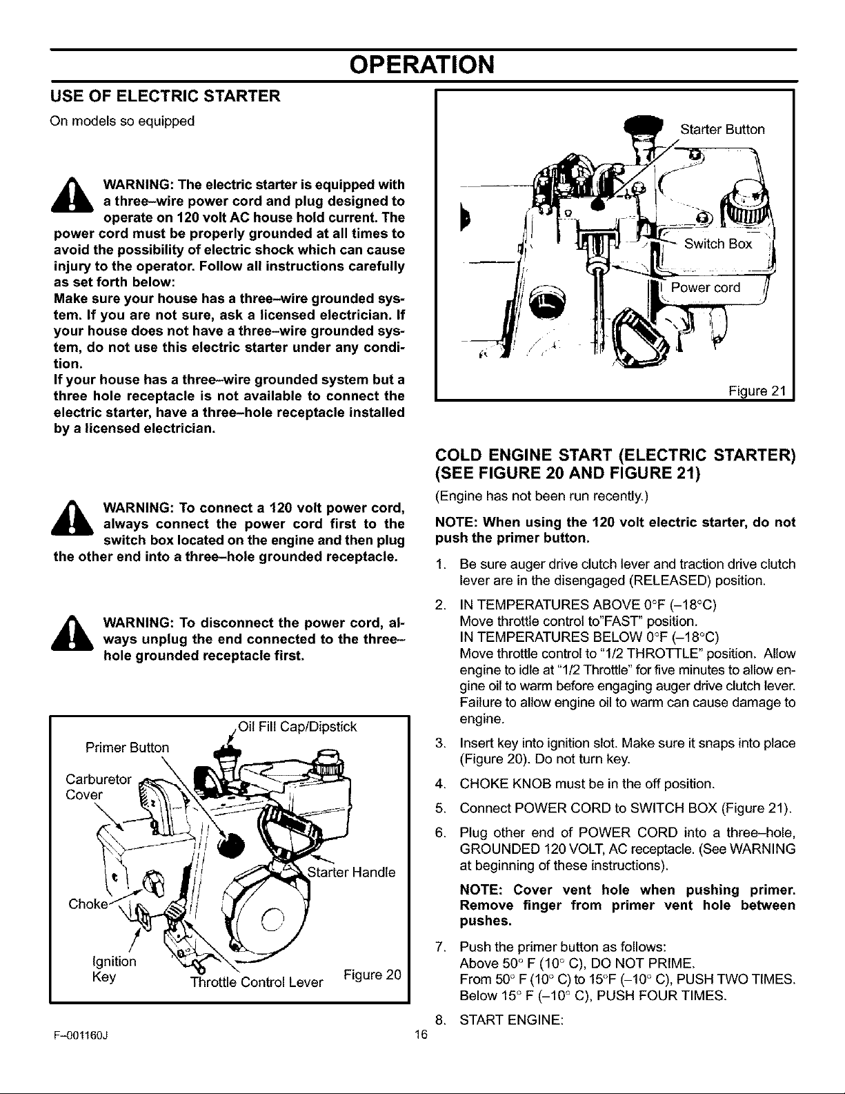
Starter Button
Power cord
Figure 21
COLD ENGINE START (ELECTRIC STARTER)
(SEE FIGURE 20 AND FIGURE 21)
(Engine has not been run recently.)
WARNING: To connect a 120 volt power cord,
always connect the power cord first to the
switch box located on the engine and then plug
the other end into a three-hole grounded receptacle.
,_ WARNING: To disconnect the power cord, al-
ways unplug the end connected to the three-
hole grounded receptacle first.
Fill Cap/Dipstick
Primer Button
Carburetor
Cover
Starter Handle
Ignition
Key Throttle Control Lever Figure 20
F_01160J 16
NOTE: When using the 120 volt electric starter, do not
push the primer button.
1.
Be sure auger drive clutch lever and traction drive clutch
lever are in the disengaged (RELEASED) position.
2.
IN TEMPERATURES ABOVE 0°F (-18°C)
Move throttle control to'FAST" position.
IN TEMPERATURES BELOW 0°F (-18°C)
Move throttle control to "1/2 THROTTLE" position. Allow
engine to idle at "1/2 Throttle" for five minutes to allow en-
gine oil to warm before engaging auger drive clutch lever.
Failure to allow engine oil to warm can cause damage to
engine.
3. Insert key intoignitionslot. Make sure it snaps into place
(Figure 20). Do not turn key.
4.
CHOKE KNOB must be in the off position.
5.
Connect POWER CORD to SWITCH BOX (Figure 21).
6.
Plug other end of POWER CORD into a three-hole,
GROUNDED 120 VOLT, AC receptacle. (See WARNING
at beginning of these instructions).
NOTE: Cover vent hole when pushing primer.
Remove finger from primer vent hole between
pushes.
7.
Push the primer button as follows:
Above 50° F (10° C), DO NOT PRIME.
From 50° F (10° C) to 15°F (-10 ° C), PUSH TWO TIMES.
Below 15° F (-10 ° C), PUSH FOUR TIMES.
8. START ENGINE:
OPERATION
a. Push STARTER BUTTON (Figure 21) to engage
starter motor and crank engine.
b. Rotate CHOKE KNOB to the on position while crank-
ing engine.
NOTE: The electric starter is thermally protected. If
overheated, the electric starter will stop
automatically and can only be restarted when it has
cooled to a safe temperature. A wait of
approximately five to ten minutes is required.
c. When engine starts, release the STARTER BUT-
TON and rotate the CHOKE KNOB gradually to the
off position.
d.
If engine falters, rotate the CHOKE KNOB immedi-
ately to the on position and then gradually to the off
position.
e.
Disconnect the POWER CORD from receptacle first,
and then from the SWITCH BOX.
9. When the engine starts, release the starter button and
move choke lever to "1/2 choke" position. When engine
does not run smoothly, move choke lever to the off posi-
tion.
NOTE: Allow the engine to warm up for several
minutes before blowing snow in temperatures below
0OF.
10. Run engine at or near top speed.
11. To stop engine, move throttle control lever to stop posi-
tion. Remove key. Do not turn key.
If, after following the preceding instructions,your engine fails
to start, have it checked by an Authorized Sears Service
Outlet.
WARM ENGINE START (ELECTRIC STARTER)
(Engine still warm from recent running.) Proceed with the
following instructions.
NOTE: Warm engine may start without choking.
1. Be sure auger drive clutch lever and traction drive clutch
lever are in the disengaged position, "RELEASED".
2.
IN TEMPERATURES ABOVE 0°F (-18°C)
Move throttle control to'FAST" position.
IN TEMPERATURES BELOW 0°F (-18°C)
Move throttle control to "1/2 THROTTLE" position. Allow
engine to idle at "1/2 Throttle" for five minutes to allow en-
gine oil to warm before engaging auger drive clutch lever.
Failure to allow engine oil to warm can cause damage to
engine.
3. Insert key intoignitionslot. Make sure it snaps into place
(Figure 17). Do not turn key.
4. CHOKE KNOB must be in the off position.
5. Connect the POWER CORD to the SWITCH BOX
(Figure 21).
6. Plug other end of POWER CORD into a three hole,
GROUNDED 120VOLT, AC receptacle (See "WARN-
ING" at beginning of these instructions).
7. START ENGINE:
a. Push STARTER BUTTON (Figure 21) to engage
starter motor and crank engine.
b. While cranking, rotate the CHOKE KNOB on the en-
gine to the on position.
NOTE: The electric starter is thermally protected. If
overheated, the electric starter will stop
automatically and can only be restarted when it has
cooled to a safe temperature. A wait of
approximately five to ten minutes is required.
c. When the engine starts, release the STARTER BUT-
TON and rotate the CHOKE KNOB gradually to the
off position.
d. If the engine falters, rotate CHOKE KNOB immedi-
ately to the on position and then gradually to the off
position.
e. Disconnect the POWER CORD from the receptacle
first and then from the SWITCH BOX.
8. Run the engine at or near top speed.
9. To stop the engine, move the throttle control lever to the
"Stop" position. Remove the ignition key. Do not turn key.
If after following the preceding instructions, your engine fails
to start, have the engine checked by an Authorized Sears
Service Outlet.
NOTE: Do not lose the ignition key. Key the ignition key
is a safe place. The engine will not start without the
ignition key,
F_01160J 17
OPERATION
OPERATING TIPS
1. For optimum snow blower efficiency, adjust ground
speed, not the throttle. REMEMBER - if the wheels slip,
forward speed will be reduced. The engine is designed
to deliver optimum performance at full throttle and must
be run at this power setting at all times.
2. Most efficient snowblowing is accomplished when snow
is removed immediately after it falls.
3. For complete snow removal, slightly overlap each swath
previously taken.
4. Snow should be discharged downwind whenever pos-
sible.
5. For normal usage, set the skids one-eighth inch (3 mm)
below the scraper bar. For extremely hard-packed snow
surfaces, the skids may be adjusted upward to insure
cleaning efficiency.
6. On gravel or crushed rock surfaces, the skids should be
set at 1-1/4 inch (32 mm) below the scraper bar (see To
Adjust Skid Height, in the Adjustment/Repair section in
this manual). Rocks and gravel must not be picked up
and thrown by the machine.
7. After the snowblowing job has been completed, allow the
engine to idle for a few minutes, to melt snow and ice ac-
cumulated on the engine.
8. Remove ice and snow accumulation from the entire s-
now blower to prevent obstructions and possible dam-
age when snow blower is subsequently operated.
9. Before starting snow blower, always inspect augers and
impeller for ice accumulation and/or debris, which could
result in snow blower damage.
10. Check oil level before every start, fill to "SAFE" indication
prior to operating snow blower.
To help avoid possible freeze-up of starter, proceed as
follows:
Recoil Starter:
With engine running, pull starter rope with a rapid continuous
full arm stroke three (3) or four (4) times.
NOTE: The unusual sound made by pulling starter rope
will not harm the engine orthe starter.
Electric Starter:
1. Connect the "POWER CORD" to the "SWITCH BOX" and
then to a 120 volt AC receptacle.
2. With engine running, push the "STARTER BUTTON"
and spin the starter for several seconds.
NOTE: The unusual sound made by spinning the
starter rope will not harm the engine or the starter.
3. Disconnect the "POWER CORD" from the receptacle
first and then from the "SWITCH BOX".
Fq)01160J 18
SERVICE RECOMMENDATIONS
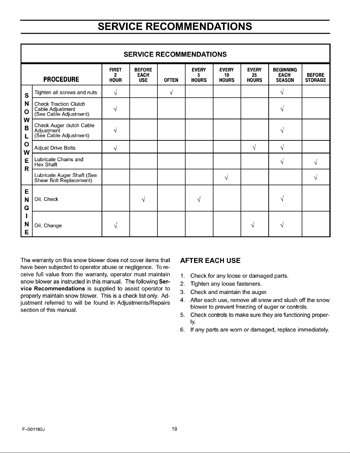
SERVICE RECOMMENDATIONS
FIRST BEFORE EVERY EVERY EVERY BEGINNING
PROCEDURE HOUR USE OFTEN HOURS HOURS HOURS SEASON STORAGE
S Tighten all screws and nuts _ _ _/
N Check Traction Clutch
Cable Ad ustment _/ _/
O (See Cabe Ad ustment)
W
Check Auger clutch Cable
B Ad ustment _/ _/
L (See Cab e Ad ustment)
O Adjust Drive Belts _/ _/ _/
W
E Lubricate Chains and _/
Hex Shaft
R
Lubricate Auger Shaft (See _/
Shear Bolt Replacement)
E
N Oil, Check _ _ _/
G
I
N Oil, Change q q _/
E
2 EACH 5 10 25 EACH BEFORE
The warranty on this snow blower does not cover items that
have been subjected to operator abuse or negligence. To re-
ceive full value from the warranty, operator must maintain
snow blower as instructed in this manual. The following Ser-
vice Recommendations is supplied to assist operator to
properly maintain snow blower. This is a check list only. Ad-
justment referred to will be found in Adjustments/Repairs
section of this manual.
AFTER EACH USE
1. Check for any loose or damaged parts.
2. Tighten any loose fasteners.
3. Check and maintain the auger.
4. After each use, remove all snow and slush off the snow
blower to prevent freezing of auger or controls.
5. Check controls to make sure they are functioning proper-
ly.
6. If any parts are worn or damaged, replace immediately.
F_01160J 19
CUSTOMER RESPONSIBILITIES
Some adjustments will need to be made periodically to
properly maintain your snow blower.
Atl adjustments in ADJUSTMENTS/REPAIRS section of this
manual should be checked at least once each season.
SNOW BLOWER
The following adjustment should be performed more than
once each season.
Auger and Traction Drive Belts should be adjusted after the
first 2 to 4 hours of use, again about mid-season and twice
each season thereafter (See To Adjust Belts paragraph in the
Adjustment/Repair section).
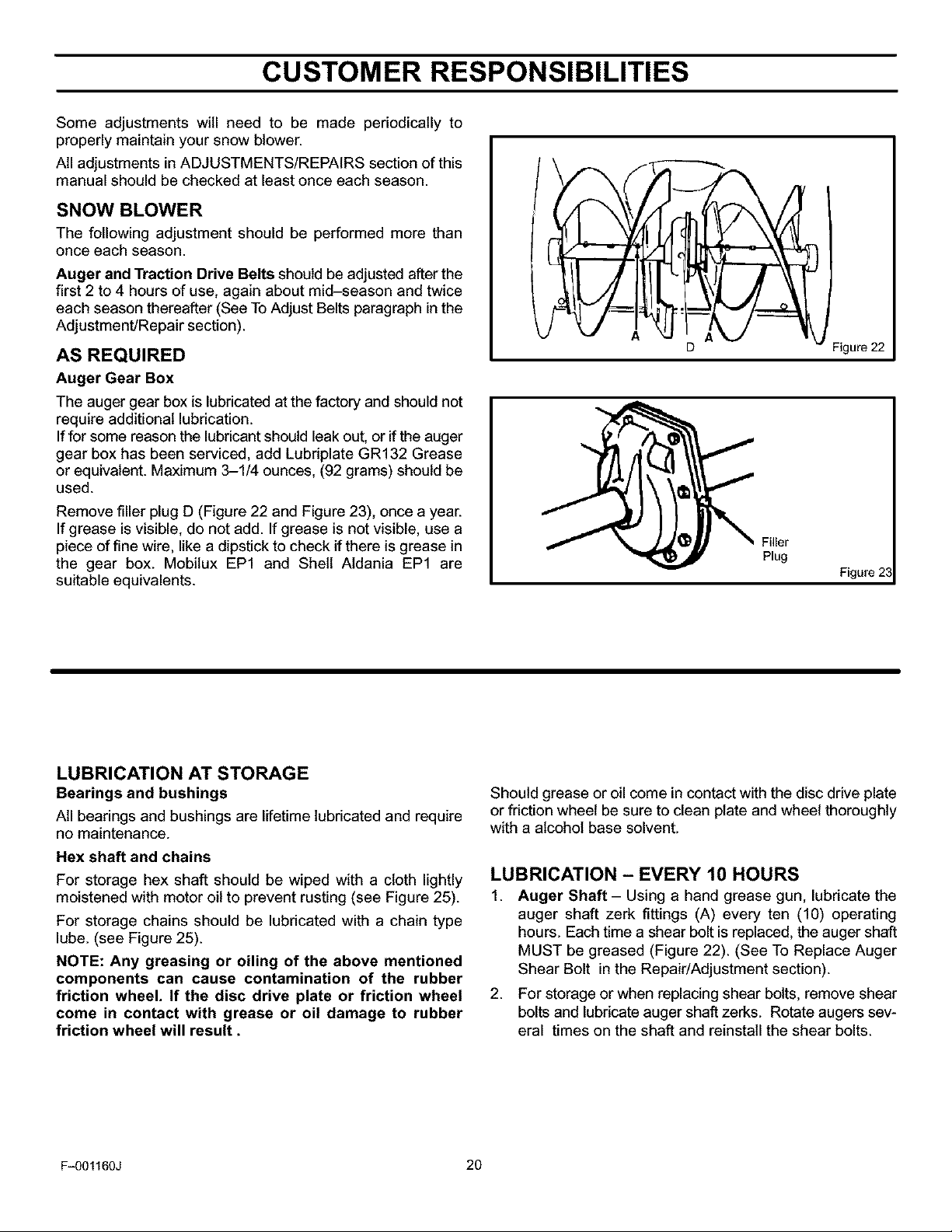
AS REQUIRED
Auger Gear Box
The auger gear box is lubricated at the factory and should not
require additional lubrication.
If for some reason the lubricant should leak out, or if the auger
gear box has been serviced, add Lubriplate GR132 Grease
or equivalent. Maximum 3-1/4 ounces, (92 grams) should be
used.
Remove filler plug D (Figure 22 and Figure 23), once a year.
If grease is visible, do not add. If grease is not visible, use a
piece of fine wire, like a dipstick to check if there is grease in
the gear box. Mobitux EP1 and Shell Atdania EP1 are
suitable equivalents.
D
Filler
Plug
Figure 22
Figure 23
LUBRICATION AT STORAGE
Bearings and bushings
All bearings and bushings are lifetime lubricated and require
no maintenance.
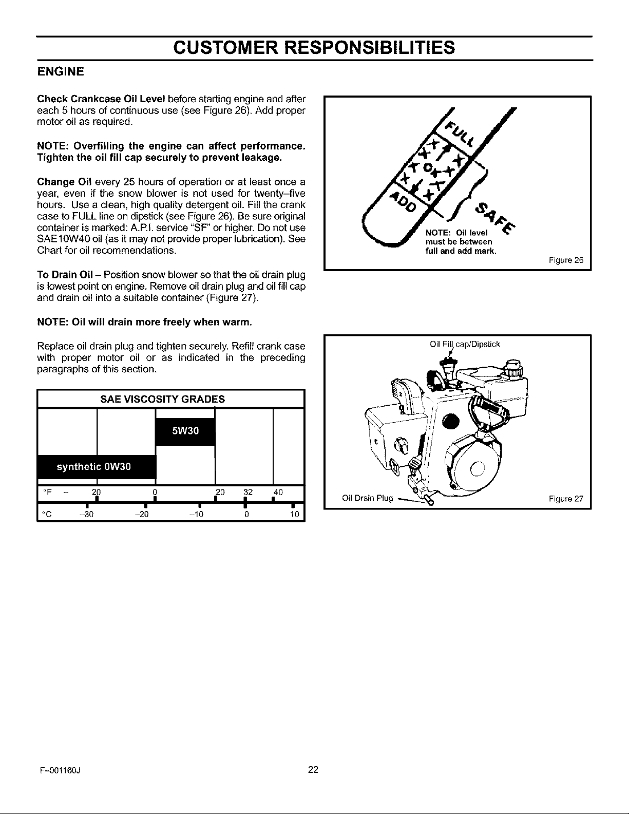
Hex shaft and chains
For storage hex shaft should be wiped with a cloth lightly
moistened with motor oil to prevent rusting (see Figure 25).
For storage chains should be lubricated with a chain type
lube. (see Figure 25).
NOTE: Any greasing or oiling of the above mentioned
components can cause contamination of the rubber
friction wheel. If the disc drive plate or friction wheel
come in contact with grease or oil damage to rubber
friction wheel will result.
F_01160J 20
Should grease or oil come in contact with the disc drive plate
or friction wheel be sure to clean plate and wheel thoroughly
with a alcohol base solvent.
LUBRICATION - EVERY 10 HOURS
1. Auger Shaft- Using a hand grease gun, lubricate the
auger shaft zerk fittings (A) every ten (10) operating
hours. Each time a shear bolt is replaced, the auger shaft
MUST be greased (Figure 22). (See To Replace Auger
Shear Bolt in the Repair/Adjustment section).
2. For storage or when replacing shear bolts, remove shear
bolts and lubricate auger shaft zerks. Rotate augers sev-
eral times on the shaft and reinstall the shear bolts.
CUSTOMER RESPONSIBILITIES
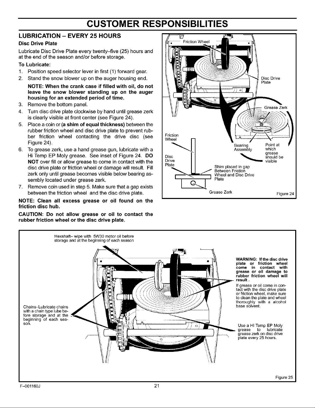
LUBRICATION - EVERY 25 HOURS
Disc Drive Plate
Lubricate Disc Drive Plate every twenty-five (25) hours and
at the end of the season and/or before storage.
To Lubricate:
1. Position speed selector lever in first (1) forward gear.
2. Stand the snow blower up on the auger housing end.
NOTE: When the crank case if filled with oil, do not
leave the snow blower standing up on the auger
housing for an extended period of time.
3. Remove the bottom panel.
4. Turn disc drive plate clockwise by hand until grease zerk
is clearly visible at front center (see Figure 24).
5. Place a coin or (a shim of equal thickness) between the
rubberfriction wheel and disc drive plate to prevent rub-
ber friction wheel contacting the drive disc (see
Figure 24).
6. To grease zerk, use a hand grease gun, lubricate with a
Hi Temp EP Moty grease. See inset of Figure 24. DO
NOT over fill or allow grease to come in contact with the
disc drive plate or friction wheel or damage will result. Fill
zerk only until grease becomes visible below bearing as-
sembly located under grease zerk.
7. Remove coinused in step 5. Make sure that a gap exists
between the friction wheel and the disc drive plate.
NOTE: Clean all excess grease or oil found on the
friction disc hub.
CAUTION: Do not allow grease or oil to contact the
rubber friction wheel or the disc drive plate.
Disc Drive
Plate
Grease Zerk
Friction
Wh_.. i i==l r_ Bearing Point at
Disc _ should be
I
Drive visible
Pla Shim placed in gap
te.__;_ _ grease
Between Friction
Wheel and Disc Drive
Plate
Grease Zerk
Assembly which
Figure 24
Hexshaft- wipe with 5W30 motor oil before
storage and at the beginning of each season
Chains-Lubricate chains
with a chain type lube be-
fore storage and at the
beginning of each sea-
son.
F_01160J 21
WARNING: If the disc drive
plate or friction wheel
come in contact with
grease or oil damage to
rubber friction wheel will
result.
If grease or oil come in con-
tact with the disc drive plate
or friction wheel, make sure
to clean the plate and wheel
thoroughly with a alcohol
base solvent.
Use a HI Temp EP Moly
grease to lubricate
grease zerk on disc drive
plate every 25 hours.
Figure 25
CUSTOMER RESPONSIBILITIES
ENGINE
Check Crankcase Oil Level before starting engine and after
each 5 hours of continuous use (see Figure 26). Add proper
motor oil as required.
NOTE: Overfilling the engine can affect performance.
Tighten the oil fill cap securely to prevent leakage.
Change Oil every 25 hours of operation or at least once a
year, even if the snow blower is not used for twenty-five
hours. Use a clean, high quality detergent oil. Fill the crank
case to FULL line on dipstick (see Figure 26). Be sure original
container is marked: A.P.I. service "SF" or higher. Do not use
SAE10W40 oil (as it may not provide proper lubrication). See
Chart for oil recommendations.
To Drain Oil - Position snow blower so that the oil drain plug
is lowest point on engine. Remove oil drain plug and oil fill cap
and drain oil into a suitable container (Figure 27).
NOTE: Oil will drain more freely when warm.
Oil level
must be between
full and add mark.
Figure 26
Replace oil drain plug and tighten securely. Refill crank case
with proper motor oil or as indicated in the preceding
paragraphs of this section.
SAE VISCOSITY GRADES
q[GvAv_II]
°F 20 0 20 32 40
°C -30 -20 -10 0 10
, = , , ,
I • • I •
Oil Drain Plug
cap/Dipstick
Figure 27
F_O1160J 22
ADJ USTM ENT/RE PAlR
,l_ WARNING: Always turn unit off, remove igni-
AUGER HOUSING HEIGHT ADJUSTMENT
TO ADJUST SCRAPER BAR
After considerable use, the metal scraper bar will have a
definite wear pattern. The scraper bar in conjunction with the
skids should always be adjusted to allow one-eighth of an
inch (3 mm) between the scraper bar and the sidewalk or
area to be cleaned.
To adjust the scraper bar, proceed as follows:
1. Position the snow blower on a level surface.
2. Loosen the carriage bolts and nuts securing the scraper
3. Adjust the scraper bar to the proper position. Tighten the
4. For extended operation, the scraper bar may be re-
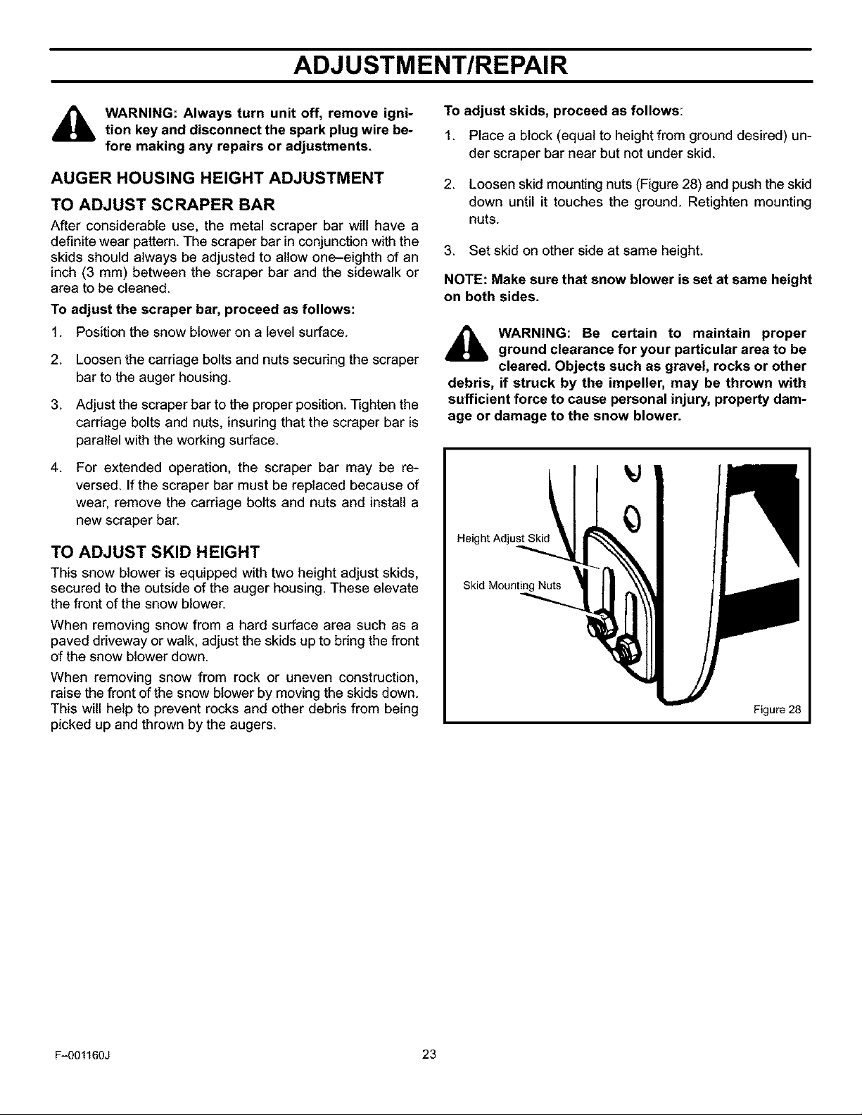
TO ADJUST SKID HEIGHT
This snow blower is equipped with two height adjust skids,
secured to the outside of the auger housing. These elevate
the front of the snow blower.
When removing snow from a hard surface area such as a
paved driveway or walk, adjust the skids up to bring the front
of the snow blower down.
When removing snow from rock or uneven construction,
raise the front of the snow blower by moving the skids down.
This will help to prevent rocks and other debris from being
picked up and thrown by the augers.
tion key and disconnect the spark plug wire be-
fore making any repairs or adjustments.
bar to the auger housing.
carriage bolts and nuts, insuring that the scraper bar is
parallel with the working surface.
versed. If the scraper bar must be replaced because of
wear, remove the carriage bolts and nuts and install a
new scraper bar.
To adjust skids, proceed as follows:
1. Place a block (equal to height from ground desired) un-
der scraper bar near but not under skid.
2. Loosen skid mounting nuts (Figure 28) and push the skid
down until it touches the ground. Retighten mounting
nuts.
3. Set skid on other side at same height.
NOTE: Make sure that snow blower is set at same height
on both sides.
_lb ARNING: Be certain to maintain proper
debris, if struck by the impeller, may be thrown with
sufficient force to cause personal injury, property dam-
age or damage to the snow blower.
ground clearance for your particular area to be
cleared. Objects such as gravel, rocks or other
Height Adjust Skic
Skid Mounting Nuts
Figure 28
F_01160J 23
ADJ USTM ENT/RE PAlR
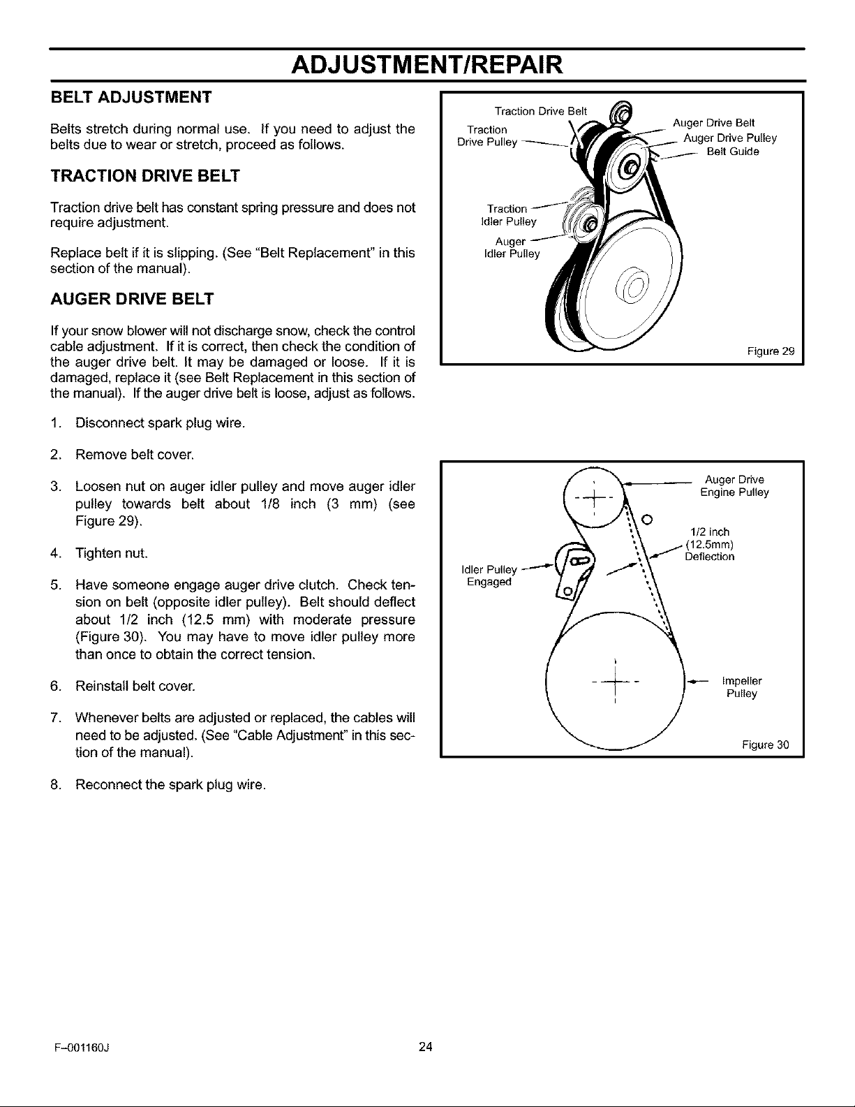
BELT ADJUSTMENT
Belts stretch during normal use. If you need to adjust the
belts due to wear or stretch, proceed as follows.
TRACTION DRIVE BELT
Traction drive belt has constant spring pressure and does not
require adjustment.
Replace belt if it is slipping. (See "Belt Replacement" inthis
section of the manual).
AUGER DRIVE BELT
If your snow blower will not discharge snow, check the control
cable adjustment. If it is correct, then check the condition of
the auger drive belt. It may be damaged or loose. If it is
damaged, replace it (see Belt Replacement in this section of
the manual). If the auger drive belt is loose, adjust as follows.
1. Disconnect spark plug wire.
2. Remove belt cover.
3. Loosen nut on auger idler pulley and move auger idler
pulley towards belt about 1/8 inch (3 mm) (see
Figure 29).
4. Tighten nut.
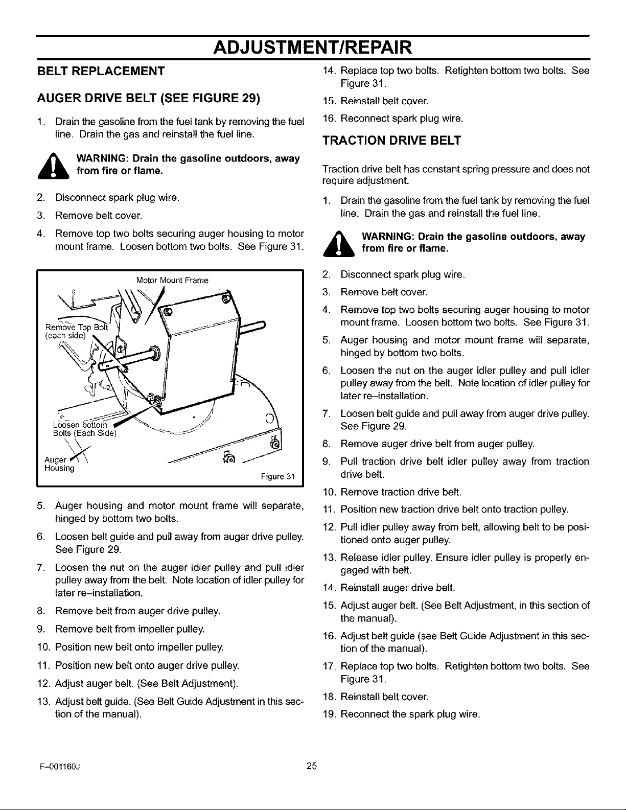
5. Have someone engage auger drive clutch. Check ten-
sion on belt (opposite idler pulley). Belt should deflect
about 1/2 inch (12.5 mm) with moderate pressure
(Figure 30). You may have to move idler pulley more
than once to obtain the correct tension.
Traction Drive Belt
Traction
Drive Pulley
l _ Auger Drive
,__/_ Engine Pu,,ey
__._ ';_O 112 inch
Idler Pulley _-'-'_/ .,_ / ",_.
Engo0ed
Auger Drive Belt
Belt Guide
Figure 29
6. Reinstall belt cover.
7. Whenever belts are adjusted or replaced, the cables will
need to be adjusted. (See "Cable Adjustment" inthis sec-
tion of the manual).
8. Reconnect the spark plug wire.
F_01160J 24
Pulley
Figure 30
ADJ USTM ENT/RE PAlR
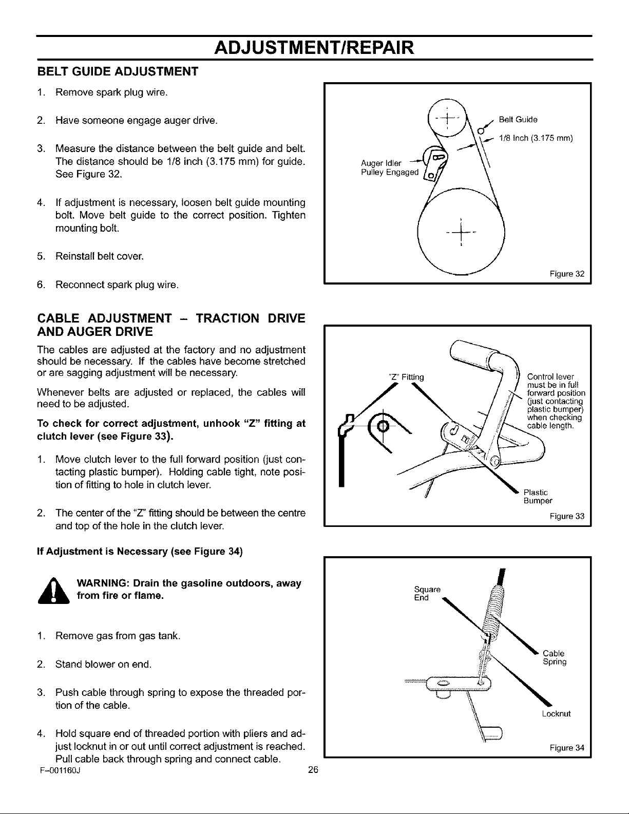
BELT REPLACEMENT
AUGER DRIVE BELT (SEE FIGURE 29)
1. Drain the gasoline from the fuel tank by removing the fuel
line. Drain the gas and reinstall the fuel line.
,_ WARNING: Drain the gasoline outdoors, awayfrom fire or flame.
2. Disconnect spark plug wire.
3. Remove belt cover.
4. Remove top two bolts securing auger housing to motor
mount frame. Loosen bottom two bolts. See Figure 31.
Motor Mount Frame
Remove Top Bolt
(each side)
14. Replace top two bolts. Retighten bottom two bolts. See
Figure 31.
15. Reinstall belt cover.
16. Reconnect spark plug wire.
TRACTION DRIVE BELT
Traction drive belt has constant spring pressure and does not
require adjustment.
1. Drain the gasoline from the fuel tank by removing the fuel
line. Drain the gas and reinstall the fuel line.
WARNING: Drain the gasoline outdoors, awayfrom fire or flame.
2. Disconnect spark plug wire.
3. Remove belt cover.
4. Remove top two bolts securing auger housing to motor
mount frame. Loosen bottom two bolts. See Figure 31.
5. Auger housing and motor mount frame will separate,
hinged by bottom two bolts.
6. Loosen the nut on the auger idler pulley and pull idler
pulley away from the belt. Note location of idler pulley for
later re-installation.
Loo_sen bottom
Bolts (Each Side)
Auger _ \
Housing
Figure 31
5. Auger housing and motor mount frame will separate,
hinged by bottom two bolts.
6. Loosen belt guide and pull away from auger drive pulley.
See Figure 29.
7. Loosen the nut on the auger idler pulley and pull idler
pulley away from the belt. Note location of idler pulley for
later re-installation.
8. Remove belt from auger drive pulley.
9. Remove belt from impeller pulley.
10. Position new belt onto impeller pulley.
11. Position new belt onto auger drive pulley.
12. Adjust auger belt. (See Belt Adjustment).
13. Adjust belt guide. (See Belt Guide Adjustment in this sec-
tion of the manual).
7. Loosen belt guide and pull away from auger drive pulley.
See Figure 29.
8. Remove auger drive belt from auger pulley.
9. Pull traction drive belt idler pulley away from traction
drive belt.
10. Remove traction drive belt.
11. Position new traction drive belt onto traction pulley.
12. Pull idler pulley away from belt, allowing belt to be posi-
tioned onto auger pulley.
13. Release idler pulley. Ensure idler pulley is properly en-
gaged with belt.
14. Reinstall auger drive belt.
15. Adjust auger belt. (See Belt Adjustment, in this section of
the manual).
16. Adjust belt guide (see Belt Guide Adjustment in this sec-
tion of the manual).
17. Replace top two bolts. Retighten bottom two bolts. See
Figure 31.
18. Reinstall belt cover.
19. Reconnect the spark plug wire.
F_01160J 25
BELT GUIDE ADJUSTMENT
1. Remove spark plug wire.
ADJ USTM ENT/RE PAlR
2. Have someone engage auger drive.
3. Measure the distance between the belt guide and belt.
The distance should be 1/8 inch (3.175 mm) for guide.
See Figure 32.
4. If adjustment is necessary, loosen belt guide mounting
bolt. Move belt guide to the correct position. Tighten
mounting bolt.
5. Reinstall belt cover.
6. Reconnect spark plug wire.
CABLE ADJUSTMENT - TRACTION DRIVE
AND AUGER DRIVE
The cables are adjusted at the factory and no adjustment
should be necessary, if the cables have become stretched
or are sagging adjustment will be necessary.
Whenever belts are adjusted or replaced, the cables will
need to be adjusted.
To check for correct adjustment, unhook "Z" fitting at
clutch lever (see Figure 33).
l -" C_ Belt Guide
Auger Idler _:_ .,......_ _- 1/8 Inch (3.175 mm)
Pulley Engaged/__
Figure 32
"Z" Fitting Control lever
forward position
(just contacting
plastic bumper)
when checking
cable length.
must be in full
1. Move clutch lever to the full forward position (just con-
tacting plastic bumper). Holding cable tight, note posi-
tion of fitting to hole in clutch lever.
2. The center of the "Z" fitting should be between the centre
and top of the hole in the clutch lever.
If Adjustment is Necessary (see Figure 34)
WARNING: Drain the gasoline outdoors, awayfrom fire or flame.
1. Remove gas from gas tank.
2. Stand blower on end.
3. Push cable through spring to expose the threaded por-
tion of the cable.
4. Hold square end of threaded portion with pliers and ad-
just Iocknut in or out until correct adjustment is reached.
Pull cable back through spring and connect cable.
Fq)01160J 26
Plastic
Bumper
Figure 33
Square
Cable
Spring
Locknut
Figure 34
ADJ USTM ENT/RE PAlR
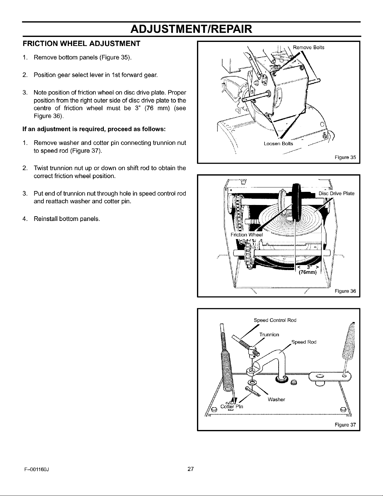
FRICTION WHEEL ADJUSTMENT
1. Remove bottom panels (Figure 35).
2. Position gear select lever in 1st forward gear.
3. Note positionof friction wheel on disc drive plate. Proper
position from the right outer side of disc drive plate to the
centre of friction wheel must be 3" (76 mm) (see
Figure 36).
If an adjustment is required, proceed as follows:
1. Remove washer and cotter pin connecting trunnion nut
to speed rod (Figure 37).
2. Twist trunnion nut up or down on shift rod to obtain the
correct friction wheel position.
3. Put end of trunnion nut through hole in speed control rod
and reattach washer and cotter pin.
4. Reinstall bottom panels.
Remove Bolts
Loosen Bolts!_
Figure 35
Disc Drive Plate
F_01160J 27
,_ Figure 36
Speed Control Rod
J ,onoion
_._ Speed Rod _
_Wa_ _" _
Cotter Pin
Figure 37
 Loading...