


 Loading...
UF-1 AND UFB-1 VALVES
TRAINING MANUAL
CARBON DIOXIDE
WATER
SYRUP/CONCENTRATE
MECHANICAL
REFRIGERATION
CONTROLS & ELECTRICAL
Blank Page

UF-1 and UFB-1 Valves Training Manual
UF-1 and UFB-1 VALVES
TRAINING MANUAL
The products, technical information, and instructions contained in this manual are subject to change without notice. These instructions are not intended to cover all details or variations of the equipment, nor to provide for every possible contingency in the installation, operation or maintenance of this equipment. This manual assumes that the person(s) working on the equipment have been trained and are skilled in working with electrical, plumbing, pneumatic, and mechanical equipment. It is assumed that appropriate safety precautions are taken and that all local safety and construction requirements are being meet, in addition to the information contained in this manual.
To inquire about current revisions of this and other documentation or for assistance with any Cornelius product contact:
IMI Cornelius Inc. |
Internet: |
|
www.cornelius.com |
|
Email: |
|
tech.service@cornelius.com |
|
|
Trademarks and copyrights:
Aurora, Cornelius, Decade, Hydro Boost, Optifill, Sitco, Spirit, UF-1, Vanguard, Venture, and Vista are registered trademarks of IMI Cornelius Inc.
This document contains proprietary information and it may not be reproduced in any way without permission from Cornelius.
Printed in U.S.A.
Copyright © 1999-2005, All Rights Reserved, IMI Cornelius Inc.
© 1999-2005, IMI Cornelius, Inc. |
- -3 - |

UF-1 Valves Manual
NOTES:
_____________________________________________________________________________
_____________________________________________________________________________
_____________________________________________________________________________
_____________________________________________________________________________
_____________________________________________________________________________
_____________________________________________________________________________
_____________________________________________________________________________
_____________________________________________________________________________
_____________________________________________________________________________
_____________________________________________________________________________
_____________________________________________________________________________
_____________________________________________________________________________
_____________________________________________________________________________
_____________________________________________________________________________
_____________________________________________________________________________
_____________________________________________________________________________
_____________________________________________________________________________
_____________________________________________________________________________
_____________________________________________________________________________
_____________________________________________________________________________
_____________________________________________________________________________
_____________________________________________________________________________
_____________________________________________________________________________

UF-1 and UFB-1 Valves Training Manual
TABLE OF CONTENTS
INTRODUCTION . . . . . . . . . . . . . . . . . . . . . . . . . . . . . . . . . . . . . . . . . . . . . . . . . . . . . . . . . . . . 1
Preview Questions . . . . . . . . . . . . . . . . . . . . . . . . . . . . . . . . . . . . . . . . . . . . . . . . . . . . . . . . . . 1
Key Things To Know / Do . . . . . . . . . . . . . . . . . . . . . . . . . . . . . . . . . . . . . . . . . . . . . . . . . . . 1
Overview . . . . . . . . . . . . . . . . . . . . . . . . . . . . . . . . . . . . . . . . . . . . . . . . . . . . . . . . . . . . . . . . . 2
Product Description . . . . . . . . . . . . . . . . . . . . . . . . . . . . . . . . . . . . . . . . . . . . . . . . . . . . . .2
Dimensions & Capacities . . . . . . . . . . . . . . . . . . . . . . . . . . . . . . . . . . . . . . . . . . . . . . . . . .4
SYSTEM DETAILS . . . . . . . . . . . . . . . . . . . . . . . . . . . . . . . . . . . . . . . . . . . . . . . . . . . . . . . . . . |
5 |
Water . . . . . . . . . . . . . . . . . . . . . . . . . . . . . . . . . . . . . . . . . . . . . . . . . . . . . . . . . . . . . . . . . . . . 5
Water Quality . . . . . . . . . . . . . . . . . . . . . . . . . . . . . . . . . . . . . . . . . . . . . . . . . . . . . . . . . . .5
Water Flow . . . . . . . . . . . . . . . . . . . . . . . . . . . . . . . . . . . . . . . . . . . . . . . . . . . . . . . . . . . . .5
Adjusting Flow Rates . . . . . . . . . . . . . . . . . . . . . . . . . . . . . . . . . . . . . . . . . . . . . . . . . . . . .6
Calculating Flow Rates . . . . . . . . . . . . . . . . . . . . . . . . . . . . . . . . . . . . . . . . . . . . . . . . . . . .7
Syrup/Concentrate . . . . . . . . . . . . . . . . . . . . . . . . . . . . . . . . . . . . . . . . . . . . . . . . . . . . . . . . . . 8
Setting Ratios . . . . . . . . . . . . . . . . . . . . . . . . . . . . . . . . . . . . . . . . . . . . . . . . . . . . . . . . . . . . . . 8
Mechanical. . . . . . . . . . . . . . . . . . . . . . . . . . . . . . . . . . . . . . . . . . . . . . . . . . . . . . . . . . . . . . . . 9
UF-1 Valve Disassembly . . . . . . . . . . . . . . . . . . . . . . . . . . . . . . . . . . . . . . . . . . . . . . . . . .9
Mounting Block Disassembly . . . . . . . . . . . . . . . . . . . . . . . . . . . . . . . . . . . . . . . . . . . . . .12
Controls and Electrical. . . . . . . . . . . . . . . . . . . . . . . . . . . . . . . . . . . . . . . . . . . . . . . . . . . . . . 13
UF-1 Portion Control Valve . . . . . . . . . . . . . . . . . . . . . . . . . . . . . . . . . . . . . . . . . . . . . . .13
Portion Control Valve Programming . . . . . . . . . . . . . . . . . . . . . . . . . . . . . . . . . . . . . 13
UF-1 OptifillTM Valve . . . . . . . . . . . . . . . . . . . . . . . . . . . . . . . . . . . . . . . . . . . . . . . . . . .14
OptifillTM Valve Programming . . . . . . . . . . . . . . . . . . . . . . . . . . . . . . . . . . . . . . . . . 14
INSTALLATION. . . . . . . . . . . . . . . . . . . . . . . . . . . . . . . . . . . . . . . . . . . . . . . . . . . . . . . . . . . . 16
Installation Requirements . . . . . . . . . . . . . . . . . . . . . . . . . . . . . . . . . . . . . . . . . . . . . . . . . . . 16
Requirements Summary . . . . . . . . . . . . . . . . . . . . . . . . . . . . . . . . . . . . . . . . . . . . . . . . . .16
Electrical Requirements . . . . . . . . . . . . . . . . . . . . . . . . . . . . . . . . . . . . . . . . . . . . . . . . . .16
Installation & Start-up . . . . . . . . . . . . . . . . . . . . . . . . . . . . . . . . . . . . . . . . . . . . . . . . . . . . . . 16
UF-1 Valve Installation Procedure . . . . . . . . . . . . . . . . . . . . . . . . . . . . . . . . . . . . . . . . . .16
INSTALLATION CHECKLIST . . . . . . . . . . . . . . . . . . . . . . . . . . . . . . . . . . . . . . . . . . . . . . 17
Retrofitting. . . . . . . . . . . . . . . . . . . . . . . . . . . . . . . . . . . . . . . . . . . . . . . . . . . . . . . . . . . . . . . 17
Mounting Block Removal . . . . . . . . . . . . . . . . . . . . . . . . . . . . . . . . . . . . . . . . . . . . . . . . .17
SERVICE . . . . . . . . . . . . . . . . . . . . . . . . . . . . . . . . . . . . . . . . . . . . . . . . . . . . . . . . . . . . . . . . . . 18
Preventative Maintenance . . . . . . . . . . . . . . . . . . . . . . . . . . . . . . . . . . . . . . . . . . . . . . . . . . . 18
Preventative Maintenance Procedures . . . . . . . . . . . . . . . . . . . . . . . . . . . . . . . . . . . . . . .18
Cleaning Valve . . . . . . . . . . . . . . . . . . . . . . . . . . . . . . . . . . . . . . . . . . . . . . . . . . . . . . . . .18
TROUBLE SHOOTING . . . . . . . . . . . . . . . . . . . . . . . . . . . . . . . . . . . . . . . . . . . . . . . . . . . . . . 19
© 1999-2005, IMI Cornelius, Inc. |
- -1 - |
CONTENTS OF TABLE

TABLE OF CONTENTS
UF-1 and UFB-1 Valves Training Manual
ATTACHMENTS . . . . . . . . . . . . . . . . . . . . . . . . . . . . . . . . . . . . . . . . . . . . . . . . . . . . . . . . . . . 23 REVIEW. . . . . . . . . . . . . . . . . . . . . . . . . . . . . . . . . . . . . . . . . . . . . . . . . . . . . . . . . . . . . . . . . . . 24
- 0 - |
© 1999-2005, IMI Cornelius Inc. |

UF-1 and UFB-1 Valves Training Manual
INTRODUCTION
1. PREVIEW QUESTIONS
Check your current knowledge by taking a few minutes to answer the following questions:
1. What are the flow capacities of a UF-1 valve? _____________________________________
|
__________________________________________________________________________ |
INTRODUCTION |
|
|
|
2. |
What are the flow capacities of a UFB-1 valve? ____________________________________ |
|
|
__________________________________________________________________________ |
|
3. |
Which syrup has the greatest pressure drop, diet or sugar?____________________________ |
|
|
__________________________________________________________________________ |
|
4. |
How do juice valves differ from carbonated beverage valves? _________________________ |
|
|
__________________________________________________________________________ |
|
5. |
Can you program “top-off” on a portion control valve? ______________________________ |
|
|
__________________________________________________________________________ |
|
6. |
What components must be replaced when retrofitting SF-1 to UF-1 valves? ______________ |
|
|
__________________________________________________________________________ |
|
2. KEY THINGS TO KNOW / DO
•For quality drinks — keep the nozzles and the water/syrup system clean; and have the correct ratio, temperature, and carbonation!
•Set the water/syrup ratio accurately — and leave it alone!
•To set the ratio accurately, set the water flow first, then the syrup!
•Be sure to cool below 40°F the syrup and water before setting the ratio.
© 1999-2005, IMI Cornelius, Inc. |
- 1 - |

INTRODUCTION
UF-1 and UFB-1 Valves Training Manual
3. OVERVIEW
3.1 Product Description
The UF-1 and UFB-1 valve provides accurate flow capability and dependability. The UF-1 and UFB-1 valves are capable of flow rates of 1 ½ to 3 ounces per second (high flow), 2 to 4 ounces per second (UFB-1), or 3 to 4 ½ ounces per second (ultra flow). The valve flow control modules are the only parts that differ in the three versions.
Note: The flow rate is also dependent on the capacity of the dispensing, cooling, and carbonation systems. An ultra flow capacity valve will not make up for a slow system flow rate or inadequate supplies of cooled water and syrup. The following is a list of Cornelius units and the valve flow rates they support:
Fast Flow |
Fast Flow, UFB-1, or Ultra Flow |
1.5 to 3.0 oz./sec. |
2 to 4 oz./sec. or 3.0 to 4.5 oz./sec. |
|
|
Vanguard |
Vanguard 245 |
Value Line 2323 (10 circuit cold plate) |
Premium 2323 (12 circuit cold plate) |
Venture |
2230 |
Vantage |
3030 |
1522 |
ED 150 |
1722 |
ED 200 |
2224 |
ED 250 |
2230-100 |
ED 300 |
DB 90 |
DF 150 |
DB 150 |
DF 200 |
DB 200 |
DF 250 |
DB 250 |
|
DB 275 |
|
TJ 45 |
|
TJ 90 |
|
TJ 150 |
|
TJ 200 |
|
TJ 250 |
|
TJ 300 |
|
TJ 400 |
|
|
|
- 2 - |
© 1999-2005, IMI Cornelius Inc. |
UF-1 and UFB-1 Valves Training Manual
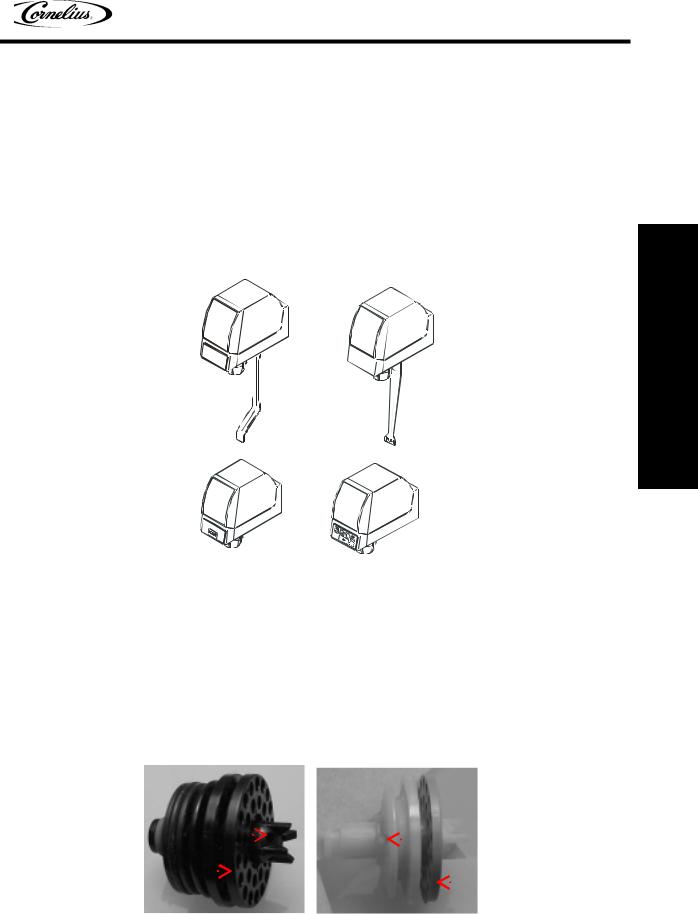
There are four varieties of UF-1 and UFB-1 valves:
•The cup activated valve dispenses by means of a lever engaged by the cup.
•A push button valve has a press and hold button on the front cover of the valve.
•The OptifillTM valve dispenses with an activation lever but stops after the liquid fills the cup and touches the lever
•A portion control valve has four programmable drink size buttons that provide timed deliveries, top off, and a manual dispensing button.
Cup |
OptifillTM |
Activated |
|
Valve |
Valve |
Push |
Portion |
Button |
Control |
Valve |
Valve |
INTRODUCTION
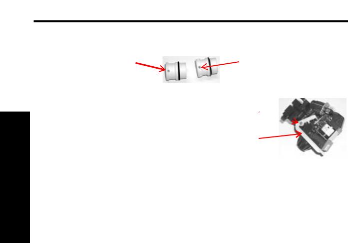
The UF-1 and UFB-1 valves are the same as described above with minor differences for juice applications. In the UF-1 and UFB-1 valve concentrate enters the nozzle assembly higher providing a better mix of concentrate and water in the cup. In addition, the orifices for concentrate are larger to avoid clogging. The concentrate diffuser is gray allowing for easy identification.
Note: The beverage (syrup) diffuser must be installed in order to use a diversion tube to ratio the concentrate valve.
Note: Concentrate valves have only one hole in their sleeve and are only offered in fast flow capacities of 1.5 to 3.0 oz./sec.
Syrup outlet |
|
|
|
|
|
|
Concentrate outlet |
|
|
|
|
|
|
|
|
|
|
|
|
|
|
|
|
|
|
(better mixing) |
Black diffuser |
|
|
|
|
|
|
|
Gray diffuser |
|
|
|
|
|
|
|
||
|
|
|
|
|
|
|
|
|
© 1999-2005, IMI Cornelius, Inc. |
- 3 - |
UF-1 and UFB-1 Valves Training Manual
INTRODUCTION
Concentrate valve sleeve has only one hole
A side water lever kit can be added to a valve allowing for dispensing of water without syrup or concentrate. The side water lever can be added to either a carbonated drink valve or a noncarbonated drink valve.
Post-mix valves control:
 Syrup valve sleeve has six holes
Mounting
screw
Water
lever
•the ON–OFF of syrup and water,
•the flow rates of syrup and water,
•the mixing of the two ingredients as they pour into the cup, and
•in some instances - dispensed portion.
3.2 Dimensions & Capacities
Fast Flow - |
- |
- |
- |
- |
- |
- |
- |
- |
- |
- |
- |
- |
- |
- |
- |
- |
- |
- |
- |
- |
- |
- |
- |
- |
- |
- |
- |
- |
- |
1 ½ to 3 oz./sec. |
UFB-1 - - |
- |
- |
- |
- |
- |
- |
- |
- |
- |
- |
- |
- |
- |
- |
- |
- |
- |
- |
- |
- |
- |
- |
- |
- |
- |
- |
- |
- |
- |
- - 2 to 4 oz./sec. |
Ultra Flow |
- - - - - - - - - |
- |
- |
- |
- |
- |
- |
- |
- |
- |
- |
- |
- |
- |
- |
- |
- |
- |
- |
- |
- |
3 to 4 ½ oz./sec. |
||||||||
Operational temperature range:- |
- |
- |
- |
- |
- |
- |
- |
- |
- |
- |
- |
- |
- 10° C (50° F) to 43° C (110° F) |
|||||||||||||||||
Voltage requirements: - - - - - |
- |
- |
- |
- |
- |
- |
- |
- |
- |
- |
- |
- |
- |
- |
- |
22 to 27 VAC (50/60 Hz) |
||||||||||||||
Transformer (electronic valves) |
- |
- |
- |
- |
- |
- |
- |
- |
- |
- |
- |
- |
- |
- |
- |
- |
- |
- |
- |
- - - 80 VA min. |
||||||||||
Operating Pressure (flowing) - |
- |
- |
- |
- |
- |
- |
- |
- |
- |
- |
- |
- |
- |
- |
- |
- |
- |
- |
- syrup = 20 psi min. |
|||||||||||
- - - - - - |
- |
- |
- |
- |
- |
- |
- |
- |
- |
- |
- |
- |
- |
- |
- |
- |
- |
- |
- |
- |
- |
- |
- |
- |
- |
- |
- |
- water = 35 psi min. |
||
Concentrates and juices that contain particulates must be dispensed from a juice valve.
A slanted drip tray is necessary when using an OptifillTM valve.
- 4 - |
© 1999-2005, IMI Cornelius Inc. |
UF-1 and UFB-1 Valves Training Manual
SYSTEM DETAILS
1.WATER
1.1Water Quality
Water quality issues have an affect on dispensing valves. Chloramine, a combination of chlorine and ammonia is responsible for some degradation of rubber components. Chloramine is used in many U. S. water supplies. Its affects can be minimized by installing and maintaining a water filtration system.
Ultra pure water affects the sensitivity of the Optifill™ valve. Because ultra pure water has less mineral content, it reduces the conductivity of the water keeping the circuit open and overfilling the beverage container.
1.2 Water Flow
The size of the orifice in the piston varies depending on whether the piston is used for syrup or water, and whether it is high flow or ultra flow valve.
Note: The notched water piston on the Ultra Flow and UFB-1
valve. results in at least one orifice in the sleeve |
Notch in |
|
always open. This eliminates pulsating and smooths |
||
piston |
||
water flow at higher flow rates. |
|
In operation the liquid flows through the knife–edged orifice in the bottom of the piston and then out the orifices in the sleeve. The outlet orifice size in the sleeve is regulated by the position of the piston. In the illustration, the piston is restricting approximately 1/2 of the outlet orifices.
UFB-1 Flow Module
Orifice
Sleeve
Piston
DETAILS SYSTEM
© 1999-2005, IMI Cornelius, Inc. |
- 5 - |
Loading...