


FlavorFusion
FlavorFusion Installation Manual
© 2005-2006, IMI Cornelius Inc. - 1 - Publication Number: 621057601INS
INSTALLATION MANUAL
FlavorFusion with Cold Carbonation
DESCRIPTION
The FlavorFusion series of dispensers solves your ice and beverage service needs in a sanitary, space
saving, economical way. Designed to be manually filled with ice from any remote ice–making source,
these dispensers will dispense cubes (up to 1–1/4 inch in size), cubelets, and compressed (not flaked)
ice. In addition, the units include beverage faucets, a cold plate, an internal carbonator tank and an
external pump for the carbonator, and are designed to be supplied direct from syrup tanks with no
additional cooling required.
CAUTION: Dispenser cannot be used with crushed or flaked ice. Use of bagged ice which has
frozen into large chunks can void warranty. The dispenser agitator is not designed to be an ice
crusher. Use of large chunks of ice which “jam up” inside the hopper will cause failure of the agitator
motor and damage to the hopper. If bagged ice is used, it must be carefully and completely broken
into small, cube-sized pieces and left to “temper” or warm up for a minimum of 20 minutes in room
temperature before loading into the dispenser hopper.
SPECIFICATION
Model Descriptions: B=Beverage
C=Coldplate
H=Internal Cold Carb
Z=No Drip Tray
Ice Storage: 255 Pounds
Maximum Number of Faucets
Available:
4 nozzles with 4 brands each = 16 brands
2 nozzles with 4 bonus flavors each = 8 bonus flavors
Built–in Cold Plate: Yes
Electrical: 120/1/60,
9.3 Amps of Total Unit Draw
220/1/50,
4.7 Amps of Total Unit Draw
Dimensions: 30 inch
30-11/16 inch
39 inch (to top of bin)
41-10/16 inch (to top of lid)
Z-Models
30 inch
23-1/16 inch
39 inch (to top of bin)
41-10/16 inch (to top of lid)
CO
2
Operating Pressure 75-psig (max) for carb tank and brand syrup pumps
25-psig (max) for bonus flavor pumps
Revision Date: February 6, 2006 Revision: B
FlavorFusion Installation Manual
Publication Number: 621057601INS - 2 - © 2005-2006, IMI Cornelius Inc.
SAFETY INSTRUCTIONS
Read and Follow all Safety Instructions
Read and follow all safety instructions in this manual and on the machine (decals, labels, and laminated
cards).
Read and understand all applicable OSHA (Occupation Safety and Health Administration) safety
regulations before operating the machine.
Recognize Safety Alerts
This is the safety alert symbol. When you see it in this manual or on the machine be alert to the
potential of personal injury or damage to the machine.
Different Types of Alerts
There are 3 types of safety alerts:
DANGER — Indicates an immediate hazardous situation which if not avoided WILL result in seri-
ous injury, death, or equipment damage.
WARNING — Indicates a potentially hazardous situation which, if not avoided, COULD result in
serious injury, death, or equipment damage.
CAUTION — Indicates a potentially hazardous situation which, if not avoided, MAY result in
minor or moderate injury or equipment damage.
Safety Tips
• Carefully read all safety messages in this manual and safety signs on the machine.
• Keep safety signs in good condition and replace missing or damaged safety signs.
• Learn how to operate the machine and how to use the controls properly.
• Do not let anyone operate the machine without proper training. This appliance is not intended for use
by very young children or infirm persons without supervision. Young children should be supervised to
ensure that they do not play with the appliance.
• Keep your machine in proper working condition and do not allow unauthorized modifications to the
machine.
Qualified Service Personnel
CAUTION — Only trained and certified electrical, plumbing and refrigeration technicians should
service this unit. ALL WIRING AND PLUMBING MUST CONFORM TO NATIONAL AND LOCAL
CODES.
CO
2
(Carbon Dioxide) Warning
WARNING — CO
2
Displaces Oxygen. Strict Attention must
be observed in the prevention of
CO
2
gas leaks in the entire CO
2
and soft drink system. If a CO
2
gas leak is suspected, particularly
in a small area, immediately ventilate the contaminated area before attempting to repair the leak.
Personnel exposed to high concentration of CO
2
gas will experience tremors which are followed
rapidly by loss of consciousness.
Shipping And Storage
CAUTION — Before shipping, storing, or relocating the Unit, syrup systems must be sanitized
and all sanitizing solution must be purged from the syrup systems. All liquids, after sanitizing, must
be purged from the unit. A freezing ambient environment will cause residual sanitizing solution or
water remaining inside the Unit to freeze resulting in damage to the internal components.

FlavorFusion Installation Manual
© 2005-2006, IMI Cornelius Inc. - 3 - Publication Number: 621057601INS
INSTALLATION
IMPORTANT: TO THE INSTALLER.
It is the responsibility of the Installer to ensure that the water supply to the dispensing equipment
is provided with protection against backflow by an air gap as defined in ANSI/ASME A112. 1.2–
1979; or an approved vacuum breaker or other such method as proved effective by test.
Water pipe connections and fixtures directly connected to a potable water supply shall be sized, installed,
and maintained according to Federal, State, and Local laws.
1. Locate the dispenser indoors on a level counter top.
A. LEG OPTION
Unpack the four (4) legs and install them into the threaded holes provided in the bottom of the
unit. The installer must provide flexibility in the product and utility supply to permit shifting the
position of the dispenser sufficiently to clean the area beneath it.
B. COUNTER MOUNTING
The ice drink dispenser must be sealed to the counter. The template drawing (see FIGURE 6)
indicates where openings can be cut in the counter. Locate the desired position for the
dispenser, then mark the outline dimensions on the counter using the template drawings. Cut
openings in counter.
Apply a continuous bead of
NSF International
(NSF) silastic sealant (Dow 732 or equal) approximately 1/
4-inch inside of the unit outline dimensions and around all openings. Then, position the unit on the
counter within the outline dimensions. All excess sealant must be wiped away immediately.
2. The beverage tubes, drain tube and power cord are routed through the large opening in the bottom
of the unit. See the MOUNTING TEMPLATE (FIGURE 6) for locating the required clearance
opening in the counter for these utility lines.
3. DRIP TRAY DRAIN ASSEMBLY (see FIGURE 7): Route the drain tube to an open drain with the
end of the tube above the “flood” level of the drain. Use the tubing, fittings, clamps, and insulation
provided with the Dispenser to assemble the drain. The completed drain line
must
pitch
continuously downward and contain no “traps” or improper drainage will result.
NOTE: IMI Cornelius Inc. recommends that a water shutoff valve and water filter be installed in
the plain water inlet supply line. A Cornelius Water Filter (P/N 313860000) and QUICK
DISCONNECT SET (P/N 313867000) are recommended.
CAUTION: Check the minimum flow rate and the maximum pressure of the plain water inlet supply
line. MINIMUM FLOW RATE MUST BE AT LEAST 125-GALLONS PER HOUR. If flow rate is less
than 125-gallons per hour, starving off the carbonator water pump will occur. Starving will allow the
carbonator water pump to overheat causing the safety thermostat on the pump outlet to stop the
water pump motor. Overheating could occur if the plain water supply line flow rate drops below 125-
gallons per hour. INCOMING PLAIN WATER INLET SUPPLY LINE WATER TO PUMP PRESSURE
MUST REMAIN A MINIMUM OF 10 psi BELOW THE CARBONATED CO
2
OPERATING
PRESSURE. (Example: Carbonator CO
2
operating pressure is 75 psi and the maximum water
pressure can be no more than 65 psi, etc.). Water over pressure (higher CO
2
operating pressure)
can cause carbonator flooding, malfunction, and leakage through the carbonator relief valve. If
water is exceeding maximum pressure specifications, a Water Pressure Regulator Kit must be
installed in the plain water inlet supply line. If fitting connector is not available, tap into the plain
water supply line with a 3/8 flare saddle valve.
4. Locate the carbonator pump assembly and connect to power cord from the Ice/Drink Unit to the
pump. The cord is connected to the unit’s electrical box and has an electrical connector on the end
that plugs into a receptacle in the junction box at the carbonator pump assembly. Connect inlet
water to pump and pump outlet to Ice/Drink Unit using 3/8-inch food-grade tubing. Disable the pump
from operating by switching the switch in the carbonator pump assembly junction box to the OFF
position.
5. Connect the beverage system product tubes as indicated in applicable Flow Diagram FIGURE 8.
This work should be done by a qualified service person.

FlavorFusion Installation Manual
Publication Number: 621057601INS - 4 - © 2005-2006, IMI Cornelius Inc.
NOTE: See applicable Flow Diagram (see FIGURE 8) or Decal on the lower front of the unit for the
location of syrup and water connections.
6. Clean the hopper interior (see CLEANING INSTRUCTIONS in Owner’s Manual).
7. Connect the unit power cord to a 120 volt, 60 cycle, 3–wire grounded receptacle. For 220-240 Volt
International Units, a 3-wire power cord is provided. An adapter plug for the particular country will
need to be provided by the Installer.
ADJUST CARBONATOR CO
2
REGULATOR AND TURN WATER INLET SUPPLY
L
INE ON
CAUTION: Before connecting the CO
2
regulator assembly to a CO
2
cylinder, turn the regulator
adjusting screw to the left (counterclockwise) until all tension is relieved from the adjusting screw
spring.
1. Open (counterclockwise) CO
2
cylinder valve slightly to allow lines to slowly fill with gas, then open
the valve fully to back-seat the valve. (Back-seating the valve prevents leakage around the valve
shaft).
2. The carbonator CO
2
regulator is fixed at a nominal 75 psi.
3. Open one of the post-mix dispensing valves to exhaust trapped air inside the carbonator tank.
4. Open the water inlet supply line shutoff valve.
UNIT OPERATION
WARNING: The unit must be electrically grounded to avoid possible fatal electrical shock or serious
injury to the operator. The unit power cord is equipped with a three-prong plug. If a three-hole
(grounded) electrical outlet is not available, use an approved method to ground the unit.
CAUTION: Never operate the carbonator pump with the water inlet supply line shutoff valve
closed. “Dry running” the water pump will burn out the pump. A pump damaged in this manner is
not covered by warranty.
1. Connect electrical power to the Unit.
2. Locate the switch on the junction box of the carbonator pump, and turn it ON. The water pump will
start and fill the carbonator tank with carbonated water. The water pump will stop when the
carbonator tank is full.
3. Check for water and CO
2
leaks, and tighten any loose connections
4. Dispense several drinks until the carbonator pump cycles on. The refill time should be about 5-7
seconds.
5. If the carbonator pump appears to be short-cycling, meaning a refill time of 1-2 seconds, refer to the
Troubleshooting section.
FlavorFusion Installation Manual
© 2005-2006, IMI Cornelius Inc. - 5 - Publication Number: 621057601INS
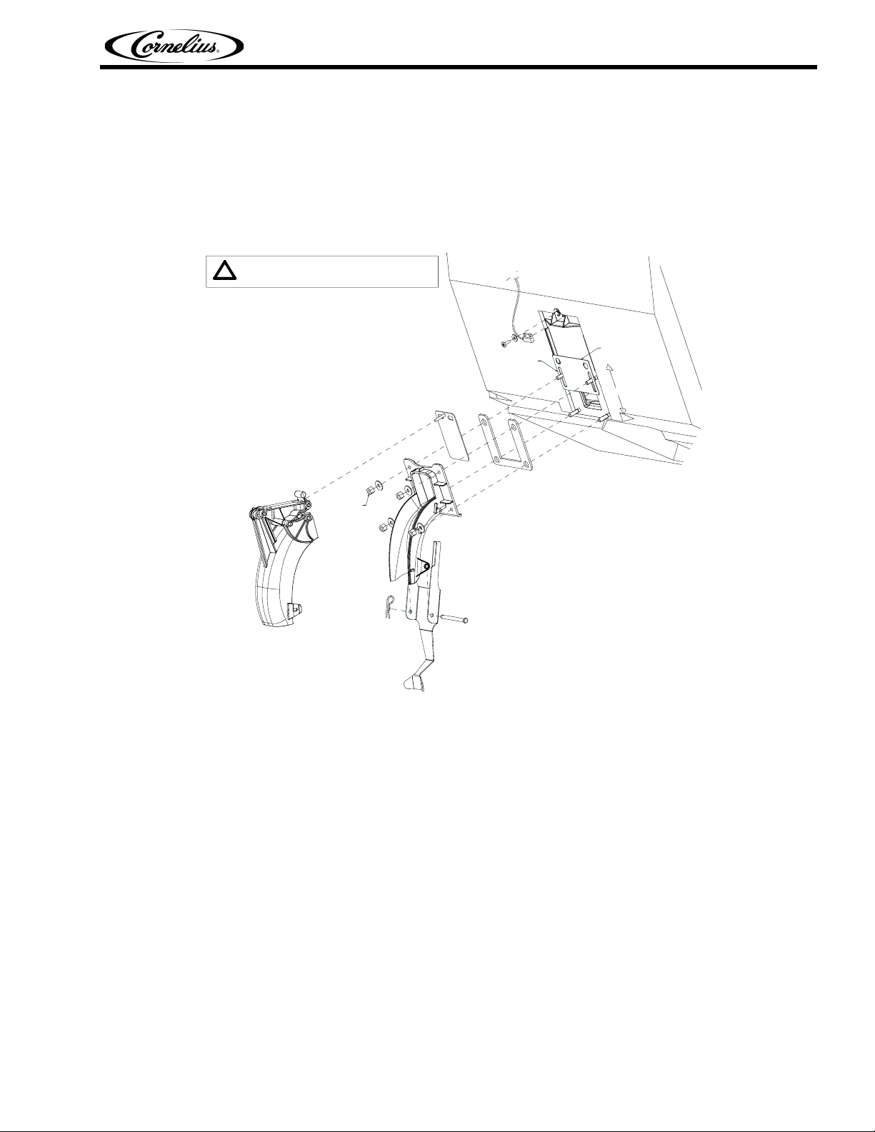
GATE RESTRICTOR PLATE AND ADJUSTMENT
The rate at which ice is dispensed can be adjusted by varying the opening of the gate restrictor plate as
illustrated in FIGURE 1. Reducing the dispense rate of ice is especially desirable when using glasses or
other containers with small openings. To adjust the gate restrictor plate, loosen the (4) nuts that hold the
ice chute assembly to the bin. The restrictor plate can now be moved up or down. When the restrictor
plate is fully up, the ice gate opening is 2-1/2” in height, and the maximum rate of ice dispense is
available (approximately 3 oz/sec). Retighten the (4) nuts to set the desired restrictor plate opening. DO
NOT EXCEED 40 IN-LB of torque.
FIGURE 1. Gate Restrictor Plate
NOTE: Tighten (4) nuts for fastening lower ice chute in place to 40 in-lbs (max). Draw all four nuts
tight uniformly.
ADJUSTMENT
INSTALL PLATE
ON STUDS AS
SHOWN
4X
MAX TORQUE
40 in.-lb.
DISCONNECT POWER BEFORE INSTALLING,
REMOVING, OR ADJUSTING RESTRICTOR.
!
RESTRICTOR
PLATE
FlavorFusion Installation Manual
Publication Number: 621057601INS - 6 - © 2005-2006, IMI Cornelius Inc.
PROGRAMMING MODE
The programming mode is exactly the same for both brand and bonus keypads.
To enter the programming mode, press and hold the two program buttons (see FIGURE 4) at the top of
the keypad for approximately 4 seconds. All keypad LEDs will flash off for approximately 1 second to
indicate the start of the programming mode.
To exit programming mode, press and hold the two program buttons for approximately 4 seconds. All
keypad LEDs will flash off for approximately 1 second, resuming normal operation mode.
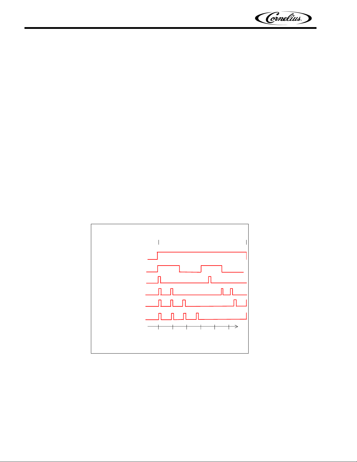
Programming Mode Flashing Sequences
Once in programming mode, each dispense button LED flashes in a sequence cycle according to one (1)
of six (6) dispense types. For Brand Keypads, only dispense types 1 and 2 are used. For Bonus Flavor
Keypads, dispense types 3 through 6 are used. The six (6) dispense types are described below, and
shown in a timing diagram in FIGURE 2:
• Dispense Type 1, Carbonated water dispense: Solid LED
• Dispense Type 2, Non-carbonated dispense: Flashing LED 1.5 seconds ON, 1.5 seconds OFF
• Dispense Type 3, 1-second flavor shot: LED flashes once for ¼ second, followed by 3 seconds
OFF
• Dispense Type 4, 2-second flavor shot: LED flashes twice for ¼ second ON, ½ second OFF,
followed by 3 seconds OFF
• Dispense Type 5, 3-second flavor shot: LED flashes three (3) times for ¼ second ON, ½ second
OFF, followed by 3 seconds OFF
• Dispense Type 6, 4-second flavor shot: LED flashes four (4) times for ¼ second ON, ½ second
OFF, followed by 3 seconds OFF
FIGURE 2
1. Carbonated water dispense
2. Non-carbonated dispense
3. 1-second flavor shot
012345
Time
(seconds)
Start
proramming
mode
Exit
programming
mode
4. 2-second flavor shot
5. 3-second flavor shot
6. 4-second flavor shot
 Loading...