


IMI CORNELIUS REMCOR INC g 500 REGENCY DRIVE g GLENDALE HEIGHTS, IL 60139--2268
Telephone (800) 551--4423 |
Facsimile (800) 519--4423 |
CHILLER (“CH” SERIES)
Models: CH 951-A
CH 1500-A
Operator’s Manual CH 1502-A
CH 1503-A
Part No. 92266
December 5, 1995
Revised: July, 1999
Revision C
THIS DOCUMENT CONTAINS IMPORTANT INFORMATION
This Manual must be read and understood before installing or operating this equipment
Ó IMI CORNELIUS INC; 1995--99
PRINTED IN U.S.A
TABLE OF CONTENTS
Page
GENERAL INFORMATION . . . . . . . . . . . . . . . . . . . . . . . . . . . . . . . . . . . . . . . . . . . . . . . . . . |
1 |
INTRODUCTION . . . . . . . . . . . . . . . . . . . . . . . . . . . . . . . . . . . . . . . . . . . . . . . . . . . . . . |
1 |
UNPACKING AND INSPECTION . . . . . . . . . . . . . . . . . . . . . . . . . . . . . . . . . . . . . . . . |
1 |
DESIGN DATA . . . . . . . . . . . . . . . . . . . . . . . . . . . . . . . . . . . . . . . . . . . . . . . . . . . . . . . . |
1 |
CHILLER INSTALLATION . . . . . . . . . . . . . . . . . . . . . . . . . . . . . . . . . . . . . . . . . . . . . . . |
1 |
LOCATION OF CHILLER . . . . . . . . . . . . . . . . . . . . . . . . . . . . . . . . . . . . . . . . . . . . . . |
1 |
ELECTRICAL CONNECTIONS . . . . . . . . . . . . . . . . . . . . . . . . . . . . . . . . . . . . . . . . . |
2 |
PROCESS CONNECTIONS . . . . . . . . . . . . . . . . . . . . . . . . . . . . . . . . . . . . . . . . . . . |
2 |
CHILLER OPERATION . . . . . . . . . . . . . . . . . . . . . . . . . . . . . . . . . . . . . . . . . . . . . . . . |
3 |
PROCESS LIQUID FLOW . . . . . . . . . . . . . . . . . . . . . . . . . . . . . . . . . . . . . . . . . . . . . |
3 |
PHASE PROTECTION / 3--PHASE MONITOR OPTION . . . . . . . . . . . . . . . . . . . |
3 |
PHASE PROTECTION / 3--PHASE OPTION ADJUSTMENT . . . . . . . . . . . . . . . |
3 |
COOLING OPERATION . . . . . . . . . . . . . . . . . . . . . . . . . . . . . . . . . . . . . . . . . . . . . . . . |
4 |
TEMPERATURE INDICATOR/CONTROLLER (THERMOSTAT) . . . . . . . . . . . . |
4 |
START--UP . . . . . . . . . . . . . . . . . . . . . . . . . . . . . . . . . . . . . . . . . . . . . . . . . . . . . . . . . . . |
5 |
THERMOSTAT CONTROL . . . . . . . . . . . . . . . . . . . . . . . . . . . . . . . . . . . . . . . . . . . . . |
5 |
CHILLER MAINTENANCE . . . . . . . . . . . . . . . . . . . . . . . . . . . . . . . . . . . . . . . . . . . . . . |
5 |
CONDENSER . . . . . . . . . . . . . . . . . . . . . . . . . . . . . . . . . . . . . . . . . . . . . . . . . . . . . . . . |
5 |
FAN MOTOR . . . . . . . . . . . . . . . . . . . . . . . . . . . . . . . . . . . . . . . . . . . . . . . . . . . . . . . . . |
5 |
PUMP MOTOR . . . . . . . . . . . . . . . . . . . . . . . . . . . . . . . . . . . . . . . . . . . . . . . . . . . . . . . |
6 |
CIRCULATION SYSTEM . . . . . . . . . . . . . . . . . . . . . . . . . . . . . . . . . . . . . . . . . . . . . . |
6 |
FILTERS/STRAINERS . . . . . . . . . . . . . . . . . . . . . . . . . . . . . . . . . . . . . . . . . . . . . . . . |
6 |
TROUBLESHOOTING . . . . . . . . . . . . . . . . . . . . . . . . . . . . . . . . . . . . . . . . . . . . . . . . . . . . . . |
7 |
CHILLER DOES NOT OPERATE, CONTROL POWER LIGHT “OFF” . . . . . . . . . |
7 |
PUMP DOES NOT OPERATE, BUT COOLING LIGHT IS ”ON”. . . . . . . . . . . . . . . |
7 |
CHILLER DOES NOT COOL, AND COOLING LIGHT IS ”OFF”. . . . . . . . . . . . . . |
7 |
PUMP RUNS, COMPRESSOR ”SHORT CYCLES”. . . . . . . . . . . . . . . . . . . . . . . . . |
7 |
UNIT RUNS CONTINUOUSLY, BUT IS NOT COOLING PROCESS LIQUID |
|
ENOUGH. . . . . . . . . . . . . . . . . . . . . . . . . . . . . . . . . . . . . . . . . . . . . . . . . . . . . . . . . . . . . |
7 |
CHILLER DOES NOT OPERATE, BUT COOLING LIGHT IS “ON”AND SAFETY |
|
LIGHT IS “ON”. . . . . . . . . . . . . . . . . . . . . . . . . . . . . . . . . . . . . . . . . . . . . . . . . . . . . . . . . |
8 |
WARRANTY . . . . . . . . . . . . . . . . . . . . . . . . . . . . . . . . . . . . . . . . . . . . . . . . . . . . . . . . . . . . . . |
14 |
LIST OF FIGURES |
|
FIGURE 1. “CH”SERIES CHILLERS . . . . . . . . . . . . . . . . . . . . . . . . . . . . . . . . . . . . . |
2 |
FIGURE 2. CONTROL PANEL . . . . . . . . . . . . . . . . . . . . . . . . . . . . . . . . . . . . . . . . . . . |
4 |
FIGURE 3. CH SERIES TEMPERATURE CONTROLLER . . . . . . . . . . . . . . . . . . . |
5 |
FIGURE 4. CABINET SECTION EXPLODED VIEW . . . . . . . . . . . . . . . . . . . . . . . . |
9 |
FIGURE 5. ELECTRICAL BOX ASSEMBLY EXPLODED VIEW . . . . . . . . . . . . . . |
11 |
FIGURE 6. PUMP AND TANK ASSEMBLY . . . . . . . . . . . . . . . . . . . . . . . . . . . . . . . |
12 |
LIST OF TABLES |
|
TABLE 1. DESIGN DATA . . . . . . . . . . . . . . . . . . . . . . . . . . . . . . . . . . . . . . . . . . . . . . . |
1 |
i |
92266 |

GENERAL INFORMATION
INTRODUCTION
The REMCOR ”CH”Series Recirculating Liquid Chiller is designed to provide an accurate, reliable, and user-- friendly system for cooling a continuous flow of pure liquid and keep that liquid at a constant temperature in various closed loop or tank cooling applications.
The ”CH”Series Chiller consists of an air--cooled refrigeration system housed in a sturdy sheet metal frame and cabinet. A standard pump and insulated liquid reservoir package provides a complete liquid cooling and circulating system.
The ”CH”Series Chiller is designed to operate in a clean laboratory or industrial environment where ambient temperatures range from 40 to100°F (5 to 38°C). With proper installation, operation, and maintenance, the ”CH”Series Chiller will provide years of trouble free service.
UNPACKING AND INSPECTION
This unit was thoroughly inspected before leaving the factory and the carrier has accepted and signed for it. Any damage or irregularities should be noted at the time of delivery and immediately reported to the carrier. Request a written inspection report from the Claims Inspector to substantiate any necessary claims. In the event that an immediate replacement is necessary, please contact REMCOR Chiller Sales at 1--800--551--4423.
DESIGN DATA
Table 1. Design Data
|
|
CH951 |
|
CH1500 |
CH1502 |
|
CH1503 |
Cooling Capacity: |
|
|
|
|
|
|
|
BTU/hr (W) at 80_F(27_C) and |
|
12,000 (3,515) |
|
18,000 (5,272) |
18,000 (5,272) |
|
18,000 (5,272) |
70_F (21_C) Liquid Temperature. |
|
|
|
|
|
|
|
|
|
|
|
|
|
|
|
Compressor Horsepower |
|
1 (.746 kW) |
|
1 1/2 (1.12 kW) |
1 1/2 (1.12 kW) |
|
1 1/2 (1.12 kW) |
|
|
|
|
|
|
|
|
Electrical Data: |
230/1/60 |
230/1/60 |
230/3/60 |
460/3/60 |
|||
Voltage/Phase/Hertz/Amperage |
|
11.0 Amps |
|
13.0 Amps |
16.4 Amps |
|
10.0 Amps |
|
|
|
|
|
|
|
|
Refrigerant Type: |
|
R134a |
|
R22 |
R22 |
|
R22 |
|
|
|
|
|
|
|
|
Reservoir Capacity |
|
6.0 gallons (22.7 |
|
6.0 gallons (22.7 |
6.0 gallons (22.7 |
|
6.0 gallons (22.7 |
|
|
liters) |
|
liters) |
liters) |
|
liters) |
|
|
|
|
|
|
|
|
Physical Dimensions, Width ¢ Depth |
|
22I¢ 26.5XI¢ |
|
22I¢ 26.5XI¢ |
22I¢ 26.5XI¢ |
|
22I¢ 26.5XI¢ |
¢ Height: |
|
38.25I |
|
38.25I |
38.25I |
|
38.25I |
|
|
(56cm ¢ 67cm |
|
(56cm ¢ 67cm |
(56cm ¢ 67cm |
|
(56cm ¢ 67cm |
|
|
¢ 97cm) |
|
¢ 97cm) |
¢ 97cm) |
|
¢ 97cm) |
|
|
|
|
|
|
|
|
Fittings: |
|
|
|
|
|
|
|
Process Connections |
|
3/4” FPT (S/S) |
|
3/4IFPT (S/S) |
3/4IFPT (S/S) |
|
3/4IFPT (S/S) |
CHILLER INSTALLATION
Location of Chiller
THE CHILLER MUST BE LOCATED NEAR A PROPERLY GROUNDED ELECTRICAL OUTLET. THE CIRCUIT SHOULD BE FUSED AND NO OTHER ELECTRICAL APPLIANCE SHOULD BE CONNECTED TO THE CIRCUIT. ALL ELECTRICAL WIRING MUST CONFORM TO NATIONAL AND LOCAL ELECTRICAL CODES.
The Chiller must be located in a well ventilated, indoor area where ambient temperatures will remain above 40_F (5_C) and will never increase above 100_F (38_C). To obtain optimum cooling capacity, the ambient temperature should be at or below 80_F (27_C).
1 |
92266 |
It is very important that the air intake and discharge sides of the chiller are not obstructed by other free standing objects. A minimum of two feet of space on all four sides of the chiller will be sufficient to prevent air flow obstructions.
It is also important to direct any hot air discharge from other equipment away from the air intake side of the chiller. Condenser air entering the “CH”unit should be below 100_F (38_C) .Condenser air temperatures above 100_F (38_C) can cause the high pressure safety control to shut down the unit.
Electrical Connections
All wiring must conform to the National Electric Code and any applicable local codes.
The “CH”unit must be PERMANENTLY wired by means of electrical conduit to a properly fused disconnect of proper amperage OR wired to a properly rated power cord and plugged into an outlet with the appropriate disconnect and amperage rating. The electrical junction box includes a four terminal strip for power supply connections. The DATA PLATE located beside the junction box indicates the phase, voltage and amperage of the chiller.
Process Connections
Follow standard plumbing practices and local codes in making liquid connections. The Chiller inlet and outlet connections are 3/4”--inch FPT couplings. It is recommended that 3/4--inch I.D. or larger flexible hose and tube fittings be used as process connections. Lines should be routed with as few bends as possible. Prevent lines from running near radiators, hot water pipes, etc. Any lengths of tubing that are exposed to high ambient temperatures should be insulated to prevent condensation and/or significant liquid heat gain.
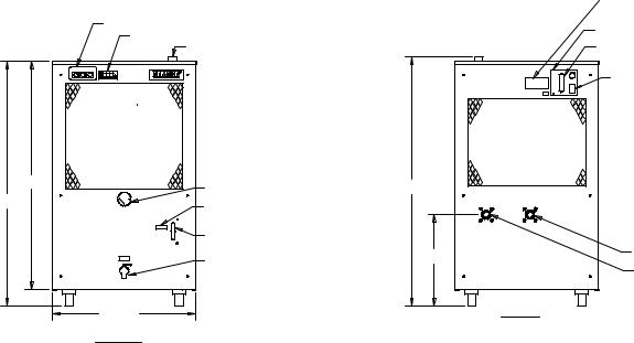
Once the system has been properly plumbed, it is important that the circulation system be filled with liquid. The reservoir can be filled by removing the fill port cap located on top of the Chiller. After ensuring that the drain is closed, fill the reservoir via the fill port with pure liquid until the liquid level sight glass on the front of the unit indicates ”FULL”. The fill port cap should then be replaced prior to operation.
CONTROL PANEL
TEMPERATURE CONTROLLER
FILL PORT
35.138
37.638
21.963 FRONT
PRESSURE GAUGE
”FULL”
RESERVOIR LEVEL INDICATOR
DRAIN
|
DATA PLATE/SERIAL NO. |
|
JUNCTION BOX |
|
TERMINAL STRIP |
|
INTERLOCK STRIP |
|
(IF APPLICABLE) |
38.224 |
|
14.000 |
OUTLET |
|
INLET |
|
REAR |
FIGURE 1. “CH” SERIES CHILLERS
92266 |
2 |
Chiller Operation
WARNING: NEVER OPERATE THE CHILLER WITH THE PANELS REMOVED.
ALWAYS USE THE POWER SWITCH TO TURN OFF THE CHILLER WHEN IT IS NOT BEING
USED.
ALWAYS ENSURE THAT ALL AIR INLETS AND OUTLETS ARE FREE FROM OBSTRUCTION. BE SURE THAT THE RESERVOIR IS FILLED WITH FLUID PRIOR TO POWERING UP THE UNIT.
Process Liquid Flow
After ensuring that the system piping is free from obstruction, that all valves are open, and the reservoir is full, push the CONTROL POWER switch to the ”ON”position. The pump should now be operating.
On three phase units such as the CH1502 and CH1503, it is important to check the pump rotation. Remove the left side panel, push the POWER button in, and observe the motor shaft. Make sure that the shaft is rotating in the direction of the arrow indicated on the pump housing. If the rotation is incorrect, reverse two of the three incoming power supply leads at the terminal strip.
NOTE: Running the pump in reverse for too long will result in permanent pump damage. The Phase Protection/3--Phase Monitor Option will prevent the pump from operating backwards. See the full description of the option for complete explanation.
All Chillers with pumps are supplied with a pressure regulating valve on the pump discharge. This valve is preset at the factory to ensure that system pressure does not exceed the capabilities of the pump motor and/or piping. If this valve requires adjustment, please contact the REMCOR Service Group for the proper setting procedure and pressures.
Once the flow has been established the thermostat can be programmed to the desired set--point.
Phase Protection / 3--Phase Monitor Option
The 3--Phase Monitor detects phase loss, low voltage, and phase reversal by continuously monitoring the 3--Phase power lines for abnormal conditions. When correct voltage and phase rotation are applied, the internal relay will energize. A fault condition will de--energize the relay. When the fault is corrected, the monitor will automatically reset. Both Trip and Norm condition indicators are provided on the relay to aid in adjustment and system trouble--shooting.
This control is located in the enclosure labeled “Monitor”on top of the electrical box.
Phase Protection / 3--Phase Option Adjustment
The following procedure will allow the 3--Phase Monitor to achieve a trip point just below the nominal phase-to- phase voltage, where the unit is applied.
Rotate the adjustment control fully clockwise, or until the red (Trip) indicator illuminated. Slowly rotate the adjustment control in a counter-clockwise direction, just until the green (Norm) indicator illuminates. At this point, the 3--Phase Monitor is the most sensitive to irregular power line conditions. If nuisance tripping occurs, turn the control slightly further counter--clockwise.
3 |
92266 |
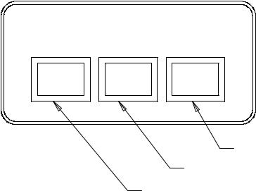
COOLING OPERATION
REMCOR CHXXX SERIES CHILLER
CONTROL
POWER |
COOLING |
SAFETY |
CONTROL PANEL
RED INDICATOR
GREEN INDICATOR
WHITE INDICATOR/PUSH BUTTON
FIGURE 2. CONTROL PANEL
Temperature Indicator/Controller (Thermostat)
Combines a precise temperature control and easy programmability with a convenient LED temperature readout that indicates system liquid temperature (2_F Differential). To adjust thermostat, see next section.
1.CONTROL POWER SWITCH/LIGHT
Asimple ON/OFF push--button that switches power to the 24 volt control circuit. When the switch is pressed, the white light on the push--button illuminates to indicate that Chiller Control Power is present. Light is no longer illuminated when button is returned to ”OFF”position.
2.COOLING LIGHT
Agreen light that illuminates to indicate that the refrigeration system is operating. This light may cycle on and off in response to the thermostat or in response to HOT GAS BYPASS if the unit is equipped with the hot--gas bypass option.
3.SAFETY LIGHT
Ared light that illuminates to indicate that a problem is present with the chiller. The safety light will illuminate under the following conditions:
A.High Refrigerant Pressure
B.Low Refrigerant Pressure
C.Low Reservoir Level (Alarm also sounds)
D.Low Evaporator Temperature
It is important to note that each of these conditions will shut down the ”CH”unit. For additional protection to your equipment, some models are equipped with a LOW FLOW INTERLOCK which terminates power to your equipment in the event that liquid flow from the ”CH”unit drops below 1.25 GPM.
92266 |
4 |
 Loading...