


www.conairnet.com
U S E R G U I D E
UGD024 /03 04
D Carousel Dryer - DC-1
Models 15, 25, 50, 75, and 100 with DC-1 Controls
INTRODUCTION • Purpose of the User Guide • How the guide is organized • Your responsibilities as a user • ATTENTION: Read this so no one gets hurt • How to use the lockout device • DESCRIPTION • What is the D Carousel Dryer? • Typical applications • How it works • Specifications: D Dryer • INSTALLATION • Unpacking the boxes • Preparing for installation • Mounting the dryer and hopper on a Processing Machine • Positioning the dryer on the floor; Mounting the hopper on the throat • Mounting the dryer on the floor stand; Hopper on the throat • Mounting the dryer and hopper on the mobile floor stand • Connecting the main power • Checking for proper air flow • Connecting the air hoses
•Connecting water hoses • Connecting the RTD probe • Mounting a loader on the hopper • OPERATION • How it works
• The DC-1 dryer control panel • D dryer DC-1 control functions • Control Function Description • To start drying • To stop drying • Using the auto start countdown function • Setting high and low setpoint limits • M A I N T E N A N C E
Corporate Office: 412.312.6000 l Instant Access 24/7 (Parts and Service): 800.458.1960 l Parts and Service: 814.437.6861

Please record your equipment’s model and serial number(s) and the date you received it in the spaces provided.
It’s a good idea to record the model and serial number(s) of your equipment and the date you received it in the User Guide. Our service department uses this information, along with the manual number, to provide help for the specific equipment you installed.
Please keep this User Guide and all manuals, engineering prints and parts lists together for documentation of your equipment.
Date:
Manual Number: UGD024/0304
Serial Number(s):
Model Number(s):
DISCLAIMER: The Conair Group, Inc., shall not be liable for errors contained in this User Guide or for incidental, consequential damages in connection with the furnishing, performance or use of this information. Conair makes no warranty of any kind with regard to this information, including, but not limited to the implied warranties of merchantability and fitness for a particular purpose.
C o p y r i g h t 2 0 0 4 l T h e C o n a i r G r o u p l A l l r i g h t s r e s e r v e d
Table of Contents
1-1 I n t r o d u c t i o n
Purpose of the User Guide . . . . . . . . . . . . . . . . . . . . . . . . . . . . . . 1-2 How the guide is organized . . . . . . . . . . . . . . . . . . . . . . . . . . . . . 1-2 Using the D series as a central dryer . . . . . . . . . . . . . . . . . . . . . . 1-3 Your responsibilities as a user . . . . . . . . . . . . . . . . . . . . . . . . . . . 1-3 ATTENTION: Read this so no one gets hurt . . . . . . . . . . . . . . . . . . 1-4 How to use the lockout device . . . . . . . . . . . . . . . . . . . . . . . . . . . 1-5
2-1 D e s c r i p t i o n
What is the D Carousel Dryer?. . . . . . . . . . . . . . . . . . . . . . . . . . . .2-2 Typical applications . . . . . . . . . . . . . . . . . . . . . . . . . . . . . . . . . . .2-2 How it works . . . . . . . . . . . . . . . . . . . . . . . . . . . . . . . . . . . . . . . .2-4 Specifications: D Dryer . . . . . . . . . . . . . . . . . . . . . . . . . . . . . . . . 2-6
3-1 I n s t a l l a t i o n
Unpacking the boxes . . . . . . . . . . . . . . . . . . . . . . . . . . . . . . . . . 3-2 Preparing for installation . . . . . . . . . . . . . . . . . . . . . . . . . . . . . . . 3-4 Mounting the dryer and hopper on a Processing Machine . . . . . . . 3-6 Positioning the dryer on the floor; Mounting the hopper
on the throat . . . . . . . . . . . . . . . . . . . . . . . . . . . . . . . . . . . 3-8 Mounting the hopper . . . . . . . . . . . . . . . . . . . . . . . . . . . . . . . . . . 3-9 Positioning the dryer on the floor . . . . . . . . . . . . . . . . . . . . . . . . . 3-9 Mounting the dryer on the floor stand; Hopper on the throat. . . . . 3-10 Mounting the dryer and hopper on the mobile floor stand . . . . . . 3-10 Connecting the main power . . . . . . . . . . . . . . . . . . . . . . . . . . . . 3-10
Ta b l e o f C o n t e n t s l i
Checking for proper air flow . . . . . . . . . . . . . . . . . . . . . . . . . . . . 3-12 Connecting the air hoses . . . . . . . . . . . . . . . . . . . . . . . . . . . . . . 3-15 Connecting water hoses. . . . . . . . . . . . . . . . . . . . . . . . . . . . . . . 3-15 Connecting the RTD probe . . . . . . . . . . . . . . . . . . . . . . . . . . . . . 3-16 Connecting the Optional Setback RTD . . . . . . . . . . . . . . . . . . . . . 3-16 Mounting a loader on the hopper . . . . . . . . . . . . . . . . . . . . . . . . 3-17 Testing the installation . . . . . . . . . . . . . . . . . . . . . . . . . . . . . . . . 3-17
4-1 O p e r a t i o n
The DC-1 dryer control panel . . . . . . . . . . . . . . . . . . . . . . . . . . . . 4-2 D dryer DC-1 control functions . . . . . . . . . . . . . . . . . . . . . . . . . . . 4-3 Control function flow chart . . . . . . . . . . . . . . . . . . . . . . . . . . . . . . 4-3 Control function descriptions . . . . . . . . . . . . . . . . . . . . . . . . . . . . 4-5 To start drying . . . . . . . . . . . . . . . . . . . . . . . . . . . . . . . . . . . . . . 4-17 To stop drying . . . . . . . . . . . . . . . . . . . . . . . . . . . . . . . . . . . . . . 4-18 Using the auto start countdown function . . . . . . . . . . . . . . . . . . . 4-19 How to enable the auto start on the DC-1 control . . . . . . . . . . . . 4-19 How to disable the auto start on the DC-1 control . . . . . . . . . . . . 4-19 Setting high and low setpoint limits . . . . . . . . . . . . . . . . . . . . . . 4-20
5-1 M a i n t e n a n c e
Preventative maintenance checklist . . . . . . . . . . . . . . . . . . . . . . . 5-2 Cleaning the hopper . . . . . . . . . . . . . . . . . . . . . . . . . . . . . . . . . . 5-3 Cleaning the process filter . . . . . . . . . . . . . . . . . . . . . . . . . . . . . . 5-4 Cleaning the regeneration filter . . . . . . . . . . . . . . . . . . . . . . . . . . 5-4 Cleaning the aftercooler coils . . . . . . . . . . . . . . . . . . . . . . . . . . . . 5-5 Cleaning the precooler coils . . . . . . . . . . . . . . . . . . . . . . . . . . . . . 5-5 Inspecting hoses and gaskets . . . . . . . . . . . . . . . . . . . . . . . . . . . 5-5
i i l Ta b l e o f C o n t e n t s
6-1 Tr o u b l e s h o o t i n g
Before beginning . . . . . . . . . . . . . . . . . . . . . . . . . . . . . . . . . . . . . 6-2 A few words of caution . . . . . . . . . . . . . . . . . . . . . . . . . . . . . . . 6-3 DIAGNOSTICS
How to identify the cause of a problem . . . . . . . . . . . . . . . . . . . . 6-4 Shut down alarms . . . . . . . . . . . . . . . . . . . . . . . . . . . . . . . . . . . 6-5 Passive alarms . . . . . . . . . . . . . . . . . . . . . . . . . . . . . . . . . . . . . 6-10 Setback . . . . . . . . . . . . . . . . . . . . . . . . . . . . . . . . . . . . . . . . . . 6-15 REPAIR
Replacing fuses. . . . . . . . . . . . . . . . . . . . . . . . . . . . . . . . . . . . . 6-17 Checking heater solid state relays . . . . . . . . . . . . . . . . . . . . . . . 6-18 Checking or replacing temperature sensors. . . . . . . . . . . . . . . . . 6-19 Adjusting the limit switch. . . . . . . . . . . . . . . . . . . . . . . . . . . . . . 6-20 Replacing the heaters . . . . . . . . . . . . . . . . . . . . . . . . . . . . . . . . 6-21 Replacing the desiccant tanks . . . . . . . . . . . . . . . . . . . . . . . . . . 6-25 Refilling the desiccant tanks. . . . . . . . . . . . . . . . . . . . . . . . . . . . 6-26
A A p p e n d i x
We’re Here to Help . . . . . . . . . . . . . . . . . . . . . . . . . . . . . . . . . . . A-1 How to Contact Customer Service . . . . . . . . . . . . . . . . . . . . . . . . A-1 Before You Call... . . . . . . . . . . . . . . . . . . . . . . . . . . . . . . . . . . . . A-1 Equipment Guarantee . . . . . . . . . . . . . . . . . . . . . . . . . . . . . . . . . A-2 Performance Warranty . . . . . . . . . . . . . . . . . . . . . . . . . . . . . . . . . A-2
B A p p e n d i x
Mounting the Dryer on a Floor Stand . . . . . . . . . . . . . . . . . . . . . . B-1 Mounting the Dryer and Hopper on a Mobile
Floor stand . . . . . . . . . . . . . . . . . . . . . . . . . . . . . . . . . . . . B-2
Ta b l e o f C o n t e n t s l i i i
C A p p e n d i x
Installing an aftercooler (optional) . . . . . . . . . . . . . . . . . . . . . . . . C-1 Cleaning the aftercooler . . . . . . . . . . . . . . . . . . . . . . . . . . . . . . . C-3
D A p p e n d i x
Installing the flow control (optional) . . . . . . . . . . . . . . . . . . . . . . . D-1
E Appendix
Installing a precooler (optional) . . . . . . . . . . . . . . . . . . . . . . . . . . E-1 Cleaning the precooler . . . . . . . . . . . . . . . . . . . . . . . . . . . . . . . . E-3
F Appendix
Installing the dew point sensor (optional) . . . . . . . . . . . . . . . . . . . F-1
G Appendix
What is the MDC? . . . . . . . . . . . . . . . . . . . . . . . . . . . . . . . . . . . G-1 Typical applications . . . . . . . . . . . . . . . . . . . . . . . . . . . . . . . . . . G-2 How conveying works. . . . . . . . . . . . . . . . . . . . . . . . . . . . . . . . . G-3 Specifications: MDC . . . . . . . . . . . . . . . . . . . . . . . . . . . . . . . . . . G-4 Unpacking the boxes . . . . . . . . . . . . . . . . . . . . . . . . . . . . . . . . . G-6 Preparing for installation . . . . . . . . . . . . . . . . . . . . . . . . . . . . . . . G-8 Installing the MDC . . . . . . . . . . . . . . . . . . . . . . . . . . . . . . . . . . . G-9 Connecting conveying lines . . . . . . . . . . . . . . . . . . . . . . . . . . . . G-10 Connecting the RTD probe . . . . . . . . . . . . . . . . . . . . . . . . . . . . G-11 Connecting the demand sensor . . . . . . . . . . . . . . . . . . . . . . . . . G-11 Connecting the main power . . . . . . . . . . . . . . . . . . . . . . . . . . . G-11 Connecting the water hoses . . . . . . . . . . . . . . . . . . . . . . . . . . . G-11 Mounting a loader on the hopper. . . . . . . . . . . . . . . . . . . . . . . . G-12 Testing the installation . . . . . . . . . . . . . . . . . . . . . . . . . . . . . . . G-12
i v l Ta b l e o f C o n t e n t s
The MDC control panel . . . . . . . . . . . . . . . . . . . . . . . . . . . . . . . G-12 MDC control functions . . . . . . . . . . . . . . . . . . . . . . . . . . . . . . . G-12 To start drying . . . . . . . . . . . . . . . . . . . . . . . . . . . . . . . . . . . . . G-12 To stop drying . . . . . . . . . . . . . . . . . . . . . . . . . . . . . . . . . . . . . G-12 Using the auto start countdown function . . . . . . . . . . . . . . . . . . G-12 Setting the high setpoint limits . . . . . . . . . . . . . . . . . . . . . . . . . G-12 To start conveying . . . . . . . . . . . . . . . . . . . . . . . . . . . . . . . . . . G-13 To stop conveying . . . . . . . . . . . . . . . . . . . . . . . . . . . . . . . . . . G-14 Transporting the MDC . . . . . . . . . . . . . . . . . . . . . . . . . . . . . . . . G-14 Preventative maintenance schedule . . . . . . . . . . . . . . . . . . . . . . G-15 Cleaning the hopper . . . . . . . . . . . . . . . . . . . . . . . . . . . . . . . . . G-15 Cleaning the conveying lines . . . . . . . . . . . . . . . . . . . . . . . . . . . G-15 Cleaning the vacuum receiver . . . . . . . . . . . . . . . . . . . . . . . . . . G-16 Cleaning the dust collector . . . . . . . . . . . . . . . . . . . . . . . . . . . . G-17 Cleaning the process filter . . . . . . . . . . . . . . . . . . . . . . . . . . . . G-18 Cleaning the regeneration filter . . . . . . . . . . . . . . . . . . . . . . . . . G-18 Cleaning the aftercooler coils . . . . . . . . . . . . . . . . . . . . . . . . . . G-18 Cleaning the precooler coils . . . . . . . . . . . . . . . . . . . . . . . . . . . G-18 Inspect hoses and gaskets . . . . . . . . . . . . . . . . . . . . . . . . . . . . G-18
Ta b l e o f C o n t e n t s l v
v i l Ta b l e o f C o n t e n t s

S E C T I O N
1
1 n o i t c u d o r t n I
I n t r o d u c t i o n
P u r p o s e o f t h e u s e r g u i d e . . . . . . . . . . . . . 1 - 2
H o w t h e g u i d e i s o r g a n i z e d . . . . . . . . . . . . 1 - 2
U s i n g t h e D s e r i e s a s a c e n t r a l d r y e r . . . . . . 1 - 3
Yo u r r e s p o n s i b i l i t i e s a s a u s e r . . . . . . . . . . 1 - 3
AT T E N T I O N :
R e a d t h i s s o n o o n e g e t s h u r t . . . . . . . . 1 - 4
H o w t o u s e t h e l o c k o u t d e v i c e . . . . . . . . . . 1 - 5
I n t r o d u c t i o n l 1 - 1
Purpose of the User Guide
This User Guide describes the Conair D series of carousel dehumidifying dryers and explains step-by-step how to install, operate, maintain and repair this equipment.
Before installing this product, please take a few moments to read the User Guide and review the diagrams and safety information in the instruction packet. You also should review manuals covering associated equipment in your system. This review won’t take long, and it could save you valuable installation and operating time later.
How the Guide is Organized
Symbols have been used to help organize the User Guide and call your attention to important information regarding safe installation and operation.
 Symbols within triangles warn of conditions that could be hazardous to users or could damage equipment. Read and take precautions before proceeding.
1
•
Numbers indicate tasks or steps to be performed by the user.
A diamond indicates the equipment’s response to an action performed by the user.
An open box marks items in a checklist.
A circle marks items in a list.
Indicates a tip. A tip is used to provide you with a suggestion that will help you with the maintenance and operation of this equipment.
Indicates a note. A note is used to provide additional information about the steps you are following throughout this manual.
1 - 2 l I n t r o d u c t i o n
Using the D Series as a Central Dr yer
This manual incorporates the information necessary to use the Conair D series dryer as a central dryer. Throughout this manual, information particular to central dyer application of the D series dryer is called out by the following treatment.
This box will contain information or highlight system differences particular to the application of the D series dryer as a central dryer.
Central
Your Responsibility as a User
You must be familiar with all safety procedures concerning installation, operation and maintenance of this equipment. Responsible safety procedures include:
•Thorough review of this User Guide, paying particular attention to hazard warnings, appendices and related diagrams.
•Thorough review of the equipment itself, with careful attention to voltage sources, intended use and warning labels.
•Thorough review of instruction manuals for associated equipment.
•Step-by-step adherence to instructions outlined in this User Guide.
1 n o i t c u d o r t n I
I n t r o d u c t i o n l 1 - 3

AT T E N T I O N :
Read this so no one gets hurt
We design equipment with the user’s safety in mind. You can avoid the potential hazards identified on this machine by following the procedures outlined below and elsewhere in the User Guide.
WARNING: Improper installation, operation, or ser vicing may result in equipment damage or personal injur y.
This equipment should be installed, adjusted, and serviced by qualified technical personnel who are familiar with the construction, operation, and potential hazards of this type of machine.
All wiring, disconnects, and fuses should be installed by qualified electrical technicians in accordance with electrical codes in your region. Always maintain a safe ground. Do not operate the equipment at power levels other than what is specified on the machine serial tag and data plate.
WARNING: Voltage hazard
This equipment is powered by three-phase alternating current, as specified on the machine serial tag and data plate.
A properly sized conductive ground wire from the incoming power supply must be connected to the chassis ground terminal inside the electrical enclosure. Improper grounding can result in severe personal injury and erratic machine operation.
Always disconnect and lock out the incoming main power source before opening the electrical enclosure or performing non-standard operating procedures, such as routine maintenance. Only qualified personnel should perform troubleshooting procedures that require access to the electrical enclosure while power is on.
1 - 4 l I n t r o d u c t i o n
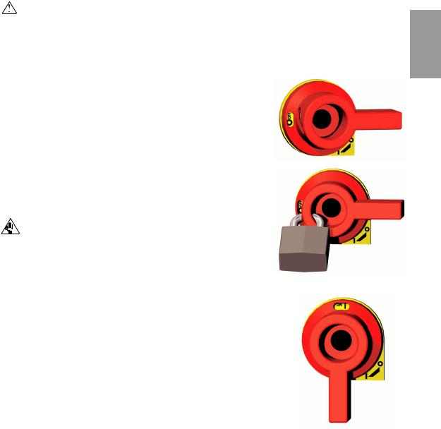
How to Use the Lockout Device
CAUTION: Before performing maintenance or repairs on this product, you should disconnect and lockout electrical power sources to prevent injury from unexpected energization or start-up. A lockable device has been provided to isolate this product from potentially hazardous electricity.
Lockout is the preferred method of isolating machines or equipment from energy sources. Your Conair product is equipped with the lockout device pictured below. To use the lockout device:
1 Stop or turn off the equipment.
2Isolate the equipment from the electric power. Turn the rotary disconnect switch to the OFF, or “O” position.
3Secure the device with an assigned lock or tag. Insert a lock or tag in the holes to prevent movement.
4 The equipment is now locked out.
WARNING: Before removing lockout devices and returning switches to the ON position, make sure that all personnel are clear of the machine, tools have been removed, and all safety guards reinstalled.
To turn the rotary disconnect back to the ON position:
1Remove the lock or tag.
2Turn the rotary disconnect switch to the ON or “I” position.
1 n o i t c u d o r t n I
I n t r o d u c t i o n l 1 - 5
1 - 6 l I n t r o d u c t i o n

D e s c r i p t i o n
W h a t i s t h e D c a r o u s e l d r y e r ? . . . . . |
. |
. |
. |
. . 2 - 2 |
||||
Ty p i c a l a p p l i c a t i o n s . . . . . . . . . . . . |
. |
. |
. |
. . 2 - 2 |
||||
H o w i t w o r k s . . . . . . . . . |
. |
. . . . . . . . . . . |
. |
2 - 4 |
||||
S p e c i f i c a t i o n s : D d r y e r . . |
. |
. . . . . . . . . . . |
. |
2 - 6 |
||||
S E C T I O N
2
2 n o i t p i r c s e D
D e s c r i p t i o n l 2 - 1
What is the D Carousel Dr yer?
The D carousel dehumidifying dryer produces hot, low-dew point air that removes moisture from hygroscopic plastics. The dryer pulls warm, moist air from a drying hopper and pumps it through dehumidifying desiccant. The dryer then heats the air to the drying temperature you selected and circulates it through the material in the hopper.
The dryer’s three-tank, closed-loop design ensures a continuous supply of hot, dehumidified air while preventing contamination from moisture in the plant.
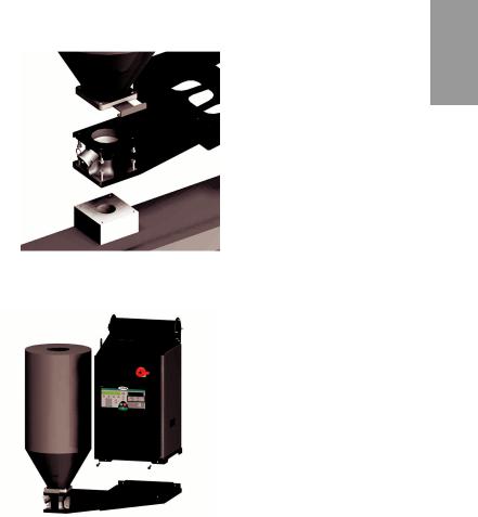
The D dryer can be mounted beside the hopper on the throat of a processing machine using the optional diving board support frame, or positioned on the floor near the machine using the standard casters. Two mobile floor stand designs are also available.
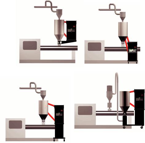
Typical Applications
Dryer and hopper on the processing |
Dryer on the floor; hopper on the throat. |
machine throat using the optional |
|
support frame. |
|
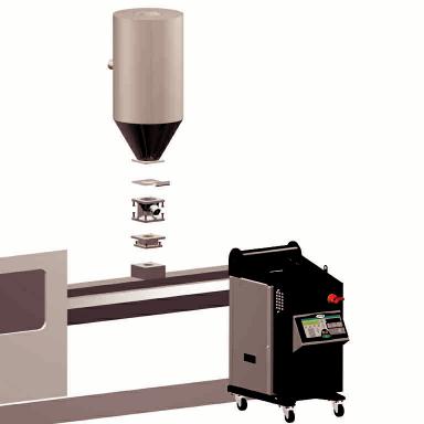
Dryer and hopper on a mobile floor stand (MDC version).
Dryer on a floor stand; hopper on the throat.
2 - 2 l D e s c r i p t i o n
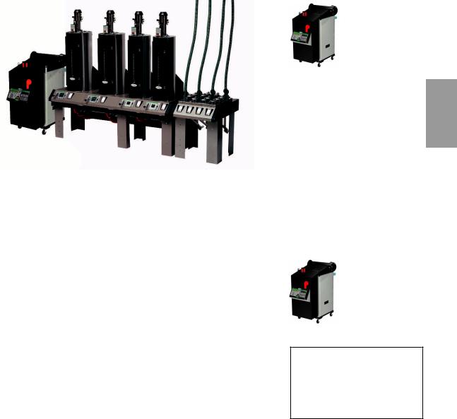
Typical Applications ( c o n t i n u e d )
Central
2 n o i t p i r c s e D
The D carousel dryer can be used successfully in applications that require:
•A contamination-free drying environment.
•Drying temperatures within the ranges shown in the following table:
Model |
Drying Temperature Range |
|
Low temperature (with precooler)* |
100° - 150°F (38° - 66°C) |
|
|
|
|
Standard |
150° - 250°F (66° - 121°C) |
|
|
|
|
High heat (with aftercooler) |
150° - 375°F (66° - 191°C) |
|
|
|
|
Low-high (with aftercooler & precooler)* |
100° - 375°F (38° - 191°C) |
|
|
|
|
*Note: See instruction on page 4-12 for setpoints over 150°F (66°C).
•Throughput rates of 15 to 100 lbs (6.8 to 37.3 kg) per hour (some materials can be run at a higher rate).
•Dew points of -40°F (-40°C).
If you are drying material at temperatures over 250°F (121°C), you will need the high-temperature package that includes an aftercooler. An aftercooler is standard equipment on the High heat and Low-high models.
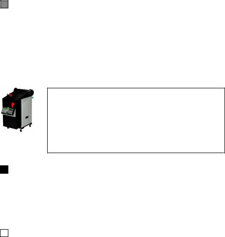
Central
When supplied for central drying applications, the D series dryer is not equipped with a process heater. Therefore, as a central dryer, the D dryer will only supply dry air to the hoppers.
D e s c r i p t i o n l 2 - 3
How It Works
The D carousel dryer achieves continuous, closed loop drying by passing air simultaneously through two heaters and three tanks of molecular sieve desiccant.
THE PROCESS (DRYING) CYCLE
The process blower pulls moist air from the top of the drying hopper. The air passes through the process filter (and optional aftercooler, if installed) into the dryer’s desiccant tank, where moisture is removed. The now dry air moves through the process heater, where it is heated to the drying temperature selected by the operator. The hot, dry air is delivered to the hopper (after it passes through the optional precooler, if installed) where a spreader cone evenly distributes the air through the material.
THE PROCESS (DRYING) CYCLE
The process blower pulls moist air from the top of the drying hopper. The air passes through the process filter (and optional aftercooler, if installed) into the dryer’s desiccant tank, where moisture is
Central
removed. The dry air is delivered to the hopper (after it passes through the optional precooler, if installed) where a spreader cone evenly distributes the air through the material.
The Regeneration Cycle
The regeneration blower pulls air through the regeneration filter into the dryer’s regeneration heater. The air is heated to 425°F (218°C) before it is pushed into the “wet” desiccant tank. The hot air purges moisture from the desiccant. The moist air is blown out the exhaust at the back of the dryer.
The Cooling Cycle
A regenerated desiccant tank must be cooled before it is moved back into the process cycle. The process blower pushes a small amount of air through the regenerated desiccant tank. The cooling air then passes through the optional aftercooler, if installed, and repeats the circuit.
2 - 4 l D e s c r i p t i o n

How It Works ( c o n t i n u e d )
1 |
1 |
6 |
|
||
|
|
PROCESS
RTD
9
HOPPER
 5
5
3
 9
9
RETURN
AIR
FILTER
8 |
RETURN AIR |
|
RTD |
DRYER OPTIONS
10 |
|
11 |
|
||
|
REGENERATION |
|
|
|
|
|
|
BLOWER |
7
REGENERATION
AIR FILTER
HIGH TEMP
HIGH TEMP  SHUTOFF
SHUTOFF
4 |
|
4 |
REGENERATION |
|
PROCESS |
HEATER |
|||
|
||||
|
HEATER BOX |
|
|
|
|
|
|
REGENERATION |
|
|
|
|
RTD |
DESICCANT |
TANKS |
BEDPLATE
2
|
PROCESS |
PROCESS |
COOLING |
BLOWER |
|
REGENERATION
1 |
SET BACK TEMPERATURE |
4 |
CURRENT METER |
7 |
PRECOOLER |
10 |
ALARM HORN |
2 |
PROCESS CFM MONITOR |
5 |
PROCESS FILTER STATUS |
8 |
AFTERCOOLER |
11 |
ALARM LIGHTS |
3 |
PM1 / DEW POINT MONITOR |
6 |
PHASE ROTATION PROTECTION |
9 |
FLOW CONTROL VALVE |
|
|
The components identified by this type of box in the drawing are not supplied with the D dryer when it is configured as a central dryer.
2 n o i t p i r c s e D
Central
D e s c r i p t i o n l 2 - 5
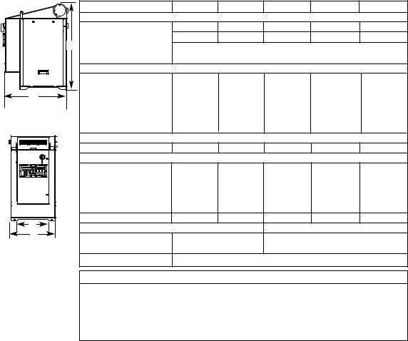
Specifications: D Carousel
DEHUMIDIFYING DRYERS
D Small Series Carousel Dryers
|
|
MODEL |
D15 |
D25 |
D50 |
D75 |
D100 |
|
|
Performance characteristics (with full hopper) |
|
|
|
|
|
|
|
Air flow {SCFM}* |
12 |
20 |
35 |
50 |
80 |
|
A |
Air flow {ACFM @ 250°}* |
16 |
27 |
47 |
67 |
107 |
|
Drying temperature |
|
All models |
100 - 375° F {38 - 191° C} with options |
|
||
|
|
|
|
||||
|
|
Dew point |
|
All models |
-40° F {-40° C} |
|
|
|
|
Dimensions inches {cm} |
|
|
|
|
|
|
|
A - Height |
35.5 {90.2} |
35.5 {90.2} |
35.5 {90.2} |
42.1 {107} |
42.1 {107} |
|
|
B - Overall width |
17.3 {43.9} |
17.3 {43.9} |
17.3 {43.9} |
22.0 {55.9} |
22.0 {55.9} |
D |
|
C - Control width |
15.7 {39.9} |
15.7 {39.9} |
15.7 {39.9} |
15.7 {39.9} |
15.7 {39.9} |
|
|
D - Depth |
24.8 {63.0} |
24.8 {63.0} |
24.8 {63.0} |
30.3 {77.0} |
30.3 {77.0} |
|
|
Control depth |
7.3 {18.5} |
7.3 {18.5} |
7.3 {18.5} |
7.3 {18.5} |
7.3 {18.5} |
|
|
Outlet/inlet tube size OD |
2.5 |
2.5 |
2.5 |
2.5 |
2.5 |
|
|
Weight lbs {kg} |
|
|
|
|
|
|
|
Installed |
225 {102} |
225 {102} |
240 {109} |
310 {141} |
340 {155} |
|
|
Voltage † Total Amps |
|
|
|
|
|
|
|
208 V/3 phase/60 Hz |
6.6 |
7.5 |
10.1 |
18.2 |
NA |
|
|
240 V/3 phase/60 Hz |
5.7 |
6.5 |
8.8 |
15.8 |
25.3 |
|
|
400 V/3 phase/50 Hz |
3.5 |
3.9 |
5.4 |
9.5 |
14 |
|
|
480 V/3 phase/60 Hz |
2.8 |
3.2 |
4.4 |
7.9 |
11.7 |
|
|
575 V/3 phase/60 Hz |
2.4 |
2.7 |
3.7 |
6.6 |
9.7 |
C |
|
Total kilowatts kw {BTU/min} |
2.2 {125} |
2.5 {142} |
3.4 {193} |
6.1 {347} |
9.0 {512} |
|
Water requirements {for optional aftercooler or precooler} |
|
|
||||
B |
|
|
|
||||
|
Recommended temperature* |
45° - 85° F |
|
45° - 85° F |
|
||
|
|
|
|
||||
|
|
Water flow gal./min. {liters/min.} |
|
1 {3.8} |
|
2 {7.6} |
|
|
|
Water connections NPT |
|
1/2 inch NPT |
|
|
|
SPECIFICATION NOTES:
*SCFM stands for standard cubic feet per minute, referenced to a pre-specified pressure, temperature and relative humidity. In most cases, SCFM is referenced to 14.7 PSIA 68° F and 0% relative humidity. ACFM stands for actual cubic feet per minute, and must be supplied with a temperature reference, due to the change in air density with temperature. Because dryers operate at a relatively low pressure the effects on air density are negligible.
† Dryers running at 50 HZ will have 17% less airflow, and a 17% reduction in material throughput.
Specifications may change without notice. Consult a Conair representative for the most current information.
2 - 6 l D e s c r i p t i o n
Specifications: D Carousel ( c o n t i n u e d )
OPTIONAL HOPPERS AND MOUNTING BRACKET
|
|
|
HOPPER MODEL |
CH10-0.5 |
CH10-1 |
CH10-1.5 |
CH14-2 |
CH14-3 |
CH14-4 |
|||||
|
|
|
Hopper / Mounting Frame Dimensions inches {cm} |
|
|
|
|
|
|
|
|
|||
|
|
|
|
A - Insulated hopper diameter |
12.5 {13.8} |
12.5 {31.8} |
12.5 {31.8} |
17 {43.2} |
17 {43.2} |
17 {43.2} |
||||
|
|
|
|
B - Overall height |
32 {81.3} |
43 {109.2} |
54 {137.2} |
45 {114.3} |
56 {142.2} |
67 {170.2} |
||||
|
A |
|
|
C - Base plate, square |
7.5 {19} |
7.5 {19} |
7.5 {19} |
6.5 {16.5} |
6.5 {16.5} |
6.5 {16.5} |
||||
|
|
|
|
D - Width with insulated hopper |
39 {99.1} |
39 {99.1} |
39 {99.1} |
41 {104.1} |
41 {104.1} |
41 {104.1} |
||||
|
|
|
Volume ft3 {liters} |
0.5 {9.4} |
1 {28.3} |
1.5 {42.5} |
2 {56.6} |
3 {85} |
4 {113.2} |
|||||
|
|
|
Capacity lb {kg} @40 lb/ft3 |
20 {9.0} |
40 {18.1} |
60 {27.2} |
80 {36.3} |
120 {54.4} |
160 {72.5} |
|||||
|
|
|
Mounting Frame Weight lb {kg} |
30 {13.6} |
30 {13.6} |
30 {13.6} |
35 {15.9} |
35 {15.9} |
35 {15.9} |
|||||
B |
|
|
Hopper Weight lb {kg} |
|
|
|
|
|
|
|
|
|
|
|
|
|
|
|
Insulated |
40 {18.1} |
50 {22.7} |
70 {31.7} |
80 {36.32} |
95 {43.1} |
110 {48.9} |
||||
|
|
|
HOPPER MODEL |
CH18-4 |
CH18-6 |
|
CH24-8 |
|
CH24-12 |
CH24-15 |
||||
|
|
|
Hopper / Mounting Frame Dimensions inches {cm} |
|
|
|
|
|
|
|
|
|||
|
C |
|
|
A - Insulated hopper diameter |
21 {53.3} |
21 {53.3} |
|
27 {68.58} |
|
27 {68.58} |
27 {68.58} |
|||
|
|
|
|
|
|
|||||||||
|
D |
|
|
B - Overall height |
48 {121.9} |
68 {172.7} |
|
64 {162.6} |
|
79 {200.7} |
90 {228.6} |
|||
|
|
|
|
C - Base plate, square |
6.5 {16.5} |
6.5 {16.5} |
|
6.5 {16.5} |
|
6.5 {16.5} |
6.5 {16.5} |
|||
|
|
|
|
D - Width |
47.63 {121.0} |
47.63 {121.0} |
47.63 |
{121.0} |
50.63 {128.6} |
50.63 {128.6} |
||||
|
|
|
Volume ft3 {liters} |
4 {113.3} |
6 {169.9} |
|
8 {226.5} |
|
12 {339.8} |
15 {424.8} |
||||
|
|
|
Capacity lb {kg} @40 lb/ft3 |
160 {72.5} |
240 {108.9} |
320 {145.1} |
|
480 {217.7} |
600 {272.2} |
|||||
|
|
|
Mounting Frame Weight lb {kg} |
50 {22.7} |
50 {22.7} |
|
70 {31.7} |
|
70 {31.7} |
70 {31.7} |
||||
|
|
|
Hopper Weight lb {kg} |
|
|
|
|
|
|
|
|
|
|
|
|
|
|
|
Insulated |
145 {66} |
165 {75} |
|
210 {95} |
|
235 {107} |
255 {116} |
|||
MOUNTING PATTERNS |
5 inches {12.7 cm} square |
Optional Base Plate |
|
3 inches {7.6 cm} square |
||||||||||
Standard Base Plate |
|
|||||||||||||
IB01 |
|
|
|
|||||||||||
|
▲ |
▲ |
|
|
|
|||||||||
IB02 |
2 inches {5.1 cm} |
|
|
1 inch {2.5 cm} |
▲ |
▲ |
|
|
||||||
(for mounting CH10 |
|
|
|
|||||||||||
|
▲ |
|
|
|
▲ 4 inches |
|||||||||
|
|
diameter |
|
6 inches |
and CH14 hoppers |
|
|
diameter |
▲ |
|
||||
|
7/16 inches {1.1 cm} |
▲ |
{15.2 cm} |
independent of dryer |
|
|
|
|
|
|
{10.2 cm} |
|||
|
▲ |
square |
only) |
7/16 inches {1.1 cm} |
▲ |
|
▲ |
square |
||||||
|
|
diameter |
▲ |
|
|
|
|
diameter |
|
|
||||
|
|
|
|
|
|
|
|
|
|
|||||
|
|
|
|
|
|
|
|
|
|
|
|
|
|
|
2 n o i t p i r c s e D
D e s c r i p t i o n l 2 - 7
2 - 8 l D e s c r i p t i o n

I n s t a l l a t i o n
U n p a c k i n g t h e b o x e s . . . . . . . . . . . . . . . . . 3 - 2 P r e p a r i n g f o r i n s t a l l a t i o n . . . . . . . . . . . . . . 3 - 4
M o u n t i n g t h e d r y e r a n d h o p p e r o n a
p r o c e s s i n g m a c h i n e . . . . . . . . . . . . . . 3 - 6
Po s i t i o n i n g t h e d r y e r o n t h e f l o o r ;
m o u n t i n g t h e h o p p e r o n t h e t h r o a t . . . . . 3 - 8 M o u n t i n g t h e h o p p e r . . . . . . . . . . . . . . . . . 3 - 9 Po s i t i o n i n g t h e d r y e r o n t h e f l o o r . . . . . . . . 3 - 9
M o u n t i n g t h e d r y e r o n t h e f l o o r s t a n d ;
h o p p e r o n t h e t h r o a t . . . . . . . . . . . . . 3 - 1 0
M o u n t i n g t h e d r y e r a n d h o p p e r o n t h e m o b i l e
f l o o r s t a n d . . . . . . . . . . . . . . . . . . . 3 - 1 0 C o n n e c t i n g t h e m a i n p o w e r . . . . . . . . . . . 3 - 1 0 C h e c k i n g f o r p r o p e r a i r f l o w . . . . . . . . . . . 3 - 1 2 C o n n e c t i n g t h e a i r h o s e s . . . . . . . . . . . . . 3 - 1 5 C o n n e c t i n g t h e w a t e r h o s e s . . . . . . . . . . . 3 - 1 5 C o n n e c t i n g t h e RT D p r o b e . . . . . . . . . . . . 3 - 1 6 C o n n e c t i n g t h e O p t i o n a l S e t b a c k RT D . . . . . 3 - 1 6 M o u n t i n g a l o a d e r o n t h e h o p p e r . . . . . . . . 3 - 1 7 Te s t i n g t h e i n s t a l l a t i o n . . . . . . . . . . . . . . 3 - 1 7
S E C T I O N
3
3 n o i t a l l a t s n I
I n s t a l l a t i o n l 3 - 1
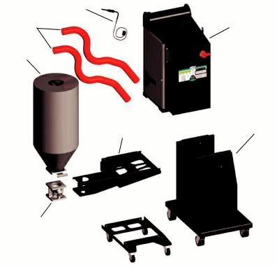
Unpacking the Boxes
The D carousel dryer comes in one to four boxes, depending on the model and options ordered. The boxes could include (depends on options selected):
RTD Probe
Mounting
Hardware:
Hoses |
D Carousel Dryer |
|
Hopper
Floor stand option:
four 5/16-18 self-locking bolts
four hose clamps
Support frame option: |
Support Frame |
Mobile Floor Stand |
|
eight 3/8-16 self-locking bolts
four 5/16-18 self-locking bolts
four hose clamps
NOTE: You must position the dryer on the floor or mount it to a floor stand if your processing machine throat opening is 1 inch (2.54 cm) diameter or smaller and requires a 3x3 inch (7.6x7.6 cm) or smaller bolt pattern.
Slide Gate
Frame  with Casters
1Carefully remove the dryer and components from their shipping containers, and set upright. Note that the dryer is secured to its shipping container with four bolts that pass through the bottom of the dryer frame. These bolts are accessed by removing the side panels of the dryer.
2Remove all packing material, protective paper, tape, and plastic, including any inserted in the top section of the dryer. Be sure to remove the side panels from the dryer and cut and remove three (3) tie wraps securing the bedplates. Also cut and remove the tie wrap on the bedplate limit switch.
3Carefully inspect all components to make sure no damage occurred during shipping, and that you have all the necessary hardware.
3 - 2 l I n s t a l l a t i o n

Unpacking the Boxes ( c o n t i n u e d )
4Take a moment to record serial numbers and electrical power specifications in the blanks provided on the back of the the User Guide’s title page. The information will be helpful if you ever need service or parts.
5You are now ready to begin installation.
Follow the preparation steps on the next page, then choose one of the four mounting options:
•Dryer and hopper on the processing machine throat using the optional support frame (see page 3-6).
•Dryer on the floor; hopper on the throat (see page 3-8).
•Dryer and hopper on a mobile floor stand (MDC mounting, see Appendix B).
•Dryer on a floor stand; hopper on the throat (see Appendix B).
3 n o i t p i r c s e D
I n s t a l l a t i o n l 3 - 3
Preparing for Installation
The D carousel dryer is easy to install if you plan the location and prepare the mounting area properly.
1Make sure the mounting area provides:
A grounded power source supplying the correct current for your dryer model. Check the dryer’s serial tag for the correct amps, voltage, phase, and cycles. Field wiring should be completed by qualified personnel to the planned location for the dryer. All electrical wiring should comply with your region’s electrical codes.
A source of water, if you have an aftercooler and / or precooler.
The D dryer’s optional aftercooler and precooler can use 1-2 gals./min. (3.8- 7.6 liters/min.) tower, city, or chiller water at temperatures of 40° to 85°F (4° to 29°C). Pipe should be run to the planned dryer location. Use flexible hose to connect the water pipes to the aftercooler and precooler. If the dryer has an optional flow control, see Appendix D for connection information.
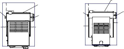
Minimum clearance for safe operation and maintenance.
You should maintain 24 in. (61 cm) clearance on at least three sides of the dryer. If the dryer is mounted with a hopper on a processing machine throat, clearance between the dryer and hopper can be 4 in. (10.2 cm).
|
Regeneration exhaust |
|
high temperature |
|
6 in. (15.24 cm) |
6 in. (15.24 cm) |
|
needed to change |
12 in. (30.48 cm) |
filter |
needed to remove |
|
optional aftercooler |
3 in. (7.62 cm) |
coil for cleaning |
|
3 in. (7.62 cm) |
|
D-15, D-25 & D-100 |
|
Minimum |
|
Clearance |
3 - 4 l I n s t a l l a t i o n |
|
|
Regeneration exhaust |
|
|
high temperature |
|
6 in. (15.24 cm) |
6 in. (15.24 cm) |
|
needed to change |
||
12 in. (30.48 cm) |
||
filter |
||
|
needed to remove |
|
|
optional aftercooler |
|
3 in. (7.62 cm) |
coil for cleaning |
|
3 in. (7.62 cm) |
||
|
||
|
D-75 & D-100 |
|
|
Minimum |
|
|
Clearance |

Preparing for Installation ( c o n t i n u e d )
A mounting surface that will support the weight of the dryer, support |
NOTE: If your mounting |
|
frame, and a fully-loaded hopper, or just the fully-loaded hopper. See the |
surface does not match |
|
specifications tables for weights and volumes. |
the standard bolt pat- |
|
|
terns available, you will |
|
Material and conveying lines installed. If you plan to use vacuum or |
need an adapter. You |
|
compressed air loaders to fill the hopper, install conveying lines to the drying |
can make an adapter |
|
using the dimensions |
||
hopper location. |
||
provided or purchase |
||
|
||
2 Drill and tap mounting holes or make adapter. |
one from Conair. |
|
|
||
Available discharge assemblies and slide gates fit mounting surfaces with |
|
|
these bolt patterns and diameters. |
|
7/16 inches |
|
7/16 inches |
|
(1.11 cm) |
|
||
|
(1.11 cm) |
||
diameter |
|
||
|
diameter |
||
|
|
||
2 inches |
6 inches |
|
4 inches |
(15.24 cm) |
|
||
|
(10.16 cm) |
||
(5.08 cm) |
square |
|
|
|
square |
||
diameter |
|
1 inch |
|
|
|
||
|
|
|
|
|
|
(2.54 cm) |
|
5 inches |
|
diameter |
3 inches |
|
|
||
(12.7 cm) |
|
|
(7.62 cm) |
square |
|
|
square |
3 n o i t p i r c s e D
I n s t a l l a t i o n l 3 - 5
Mounting the Dr yer and Hopper on a Processing Machine
 WARNING: You are responsible for the structural integrity of this installation.
We recommend that you:
Use bolts no smaller than 3/8 inch (M 10) when mounting the hopper/dryer combination to the throat of a processing machine.
Do not mount the hopper/dryer combination on a plate that swings away or slides away from the processing machine throat. Either remove the swing or slide plate, position the dryer on the floor, or mount the dryer to an optional floor stand.
Tools for installation:
Flathead screwdriver
9/16” and 1/2” wrench
Hoist
NOTE: You must position the dryer on the floor or mount it to
an optional floor stand if your processing machine throat requires the small discharge assembly or a mounting plate with less than a 3 x 3 in.
(7.6 x 7.6 cm) bolt pattern and
1 in. (2.54 cm) diameter opening.
3 - 6 l I n s t a l l a t i o n
The dryer and hopper mount on a support frame / discharge assembly that bolts to the throat of the processing machine, as pictured above.
CAUTION: To prevent accident and injury, lift the empty hopper and support frame onto the throat of the processing machine using a hoist and the lifting lugs provided. After the hopper is mounted, then lift the dryer onto the support frame using a hoist and the lifting lugs provided.
Mounting the Dr yer and Hopper on a Processing Machine
The drying hopper, slide gate, support frame, and discharge assembly may have been shipped fully assembled. You can remove the hopper from the support frame, if you find it easier to lift and bolt the frame and then the hopper to the throat of the processing machine.
1Lift the hopper, support frame, and discharge assembly onto the processing machine throat. Use a hoist to lift the support frame and hopper. Position the frame and discharge assembly so that its bolt holes line up with the holes drilled in the throat. If hole patterns do not match, you can place a mounting adapter between the throat and the support frame.
2Bolt the frame and discharge assembly to the throat. Using four 3/8 in. -16 (M 10) self-locking bolts, fasten the support frame and discharge assembly to the throat. The bolts must be long enough to reach at least 1/2 in. (1.25 cm) into the processing machine throat or mounting adapter after passing through the discharge assembly and support frame.
NOTE: If you removed the hopper from the support frame, lift the hopper onto the frame using
a hoist. Make sure the slide gate is positioned in the recess on the bottom of the hopper base plate. Align the bolt holes and fasten the base plate to the discharge assembly using the four 3/8 in. -16 (M 10) self-locking bolts
provided.
3Lift the dryer onto the support frame using a hoist and the lifting lugs provided. Align the four bolt holes on the bottom of the dryer with the four bolt holes on the top of the support frame. Fasten the dryer to the frame with 5/16 in. -18 bolts.
3 n o i t p i r c s e D
I n s t a l l a t i o n l 3 - 7
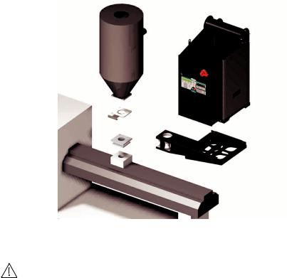
Positioning the Dr yer on the Floor; Mounting the Hopper on the Throat
 WARNING: You are responsible for the structural integrity of this installation.
We recommend that you:
•Use bolts no smaller than 3/8 in. (M 10) to mount the hopper on the throat of a processing machine.
Tools for installation:
9/16” wrench
Flathead screwdriver
Hoist
The hopper bolts to the throat of the processing machine, as pictured above. The dryer can be positioned on the floor near the processing machine.
3 - 8 l I n s t a l l a t i o n
 Loading...