


Deskpro
Table of contents
 Loading...
Technical
Reference
Guide
For the
Compaq Deskpro EN Series of Personal Computers
Desktop and Minitower Form Factors

This hardcopy is designed to be placed into a standard 3-ring binder. Provided below is a title block that
can be copied and cut out and placed into the slip or taped onto the edge of the binder.
Deskpro EN Series of Personal Computers
Deskto
p
and Minitower Form Factors
TRG

Reader Feedback
Please feel free to send any questions, suggestions, corrections, or comments regarding this
document please to the following email address:
Desktop.training.feedback@Compaq.com
When responding, please state the title of the referenced document.

Technical Reference Guide
Compaq Deskpro EN Series of Personal Computers
Desktop and Minitower Form Factors
Third Edi tion - September 1998
i
NOTICE
The information in this document is subject to change without notice.
COMPAQ COMPUTER CORPORATION SHALL NOT BE LIABLE FOR TECHNICAL OR
EDITORIAL ERRORS OR OMISSIONS HEREIN; NOR FOR INCIDENTAL OR
CONSEQUENTIAL DAMAGES RESULTING FROM THE FURNISHING, PERFORMANCE,
OR USE OF THIS MATERIAL. IT IS THE RESPONSIBILITY OF MANUFACTURERS TO
ENSURE THAT DEVICES DESIGNED TO BE USED WITH COMPAQ PRODUCTS
COMPLY WITH FCC CLASS B EMISSIONS REQUIREMENTS.
This guide contains information protected by copyright. No part of this document may be
photocopied or reproduced in any form without prior written consent from Compaq Computer
Corporation.
1998 Compaq Co mputer Cor poration
All rights reserved. Printed in the US A
Compaq, Deskpro, LTE, Contura, Presario, ProLinea
Registered U.S. Patent and Trademark Office
Product names mentioned in this document may be trademarks and/or registered trademarks of other companies.
“Pentium” and “MMX ” are trad emarks of Intel Corporation.
“Windows” is a trademark of Microsoft Corporation.
For more information regarding specifications and Compaq-specific parts please contact Compaq
Computer Corporation.
Technical Reference Guide
for
Compaq Deskpro EN Series of Personal Computers, Desktop and Minitower Form Factors
Third Edition - Se ptember 1998
Documen t Number DSK-113C /0498

Technical Reference Guide
Compaq Deskpro EN Series of Personal Computers
Desktop and Minitower Form Factors
Third Edi tion–- September1998
ii

Technical Reference Guide
Compaq Deskpro EN Series of Personal Computers
Desktop and Minitower Form Factors
Third Edi tion - September 1998
iii
TABLE OF CONTENTS
CHAPTER 1 INTRODUCTION.............................................................................................................
1.1 ABOUT THIS GUIDE...........................................................................................................1-1
1.1.1 USING THIS GUIDE.....................................................................................................1-1
1.1.2 ADDITIONAL INFORMATION SOURCES.................................................................. 1-1
1.2 NOT ATIONAL CONVENTIONS .......................................................................................... 1-2
1.2.1 VALUES........................................................................................................................ 1-2
1.2.2 RANGES........................................................................................................................ 1-2
1.2.3 SIGNAL LABELS.......................................................................................................... 1-2
1.2.4 REGISTER NOTATION AND USAGE .........................................................................1-2
1.2.5 BIT NOTATION............................................................................................................1-2
1.3 C OMMON ACRONYMS AND ABBREVIATIONS..............................................................1-3
CHAPTER 2 SYSTE M OVERVIEW .....................................................................................................
2.1 INTRODUCTION..................................................................................................................2-1
2.2 FE ATURES AND OPTIONS................................................................................................. 2-2
2.2.1 STANDARD FEATURES..............................................................................................2-2
2.2.2 OPTIONS.......................................................................................................................2-3
2.3 MECHANICAL DESIGN......................................................................................................2-4
2.3.1 CABINET LAYOUTS.................................................................................................... 2-4
2.3.2 CHASSIS LAYOUTS..................................................................................................... 2-6
2.3.3 BOARD LAYOUTS....................................................................................................... 2-8
2.4 SYSTEM ARCHITECTURE................................................................................................2-10
2.4.1 PROCESSOR...............................................................................................................2-12
2.4.2 SYSTEM MEMORY....................................................................................................2-13
2.4.3 SUPPORT CHIPSET.................................................................................................... 2-13
2.4.4 MASS STORAGE........................................................................................................ 2-13
2.4.5 SERIAL AND PARALLEL INTERFACES .................................................................. 2-14
2.4.6 UNIVERSAL SERIAL BUS INTERFACE................................................................... 2-14
2.4.7 GRAPHICS SUBSYSTEM........................................................................................... 2-14
2.4.8 AUDIO SUBSYSTEM.................................................................................................2-14
2.5 SPECIFICATIONS..............................................................................................................2-15
CHAPTER 3 PROCESSOR/MEMORY SUBSYSTEM........................................................................
3.1 INTRODUCTION..................................................................................................................3-1
3.2 PROCE SSOR/ME MORY SUBSYSTEM .............................................................................. 3-2
3.2.1 PROCESSOR.................................................................................................................3-3
3.2.2 PROCESSOR CHANGING/UPGRADING..................................................................... 3-5
3.2.3 SYSTEM MEMORY......................................................................................................3-6
3.2.4 SUBSYSTEM CONFIGURATION.................................................................................3-9

Technical Reference Guide
Compaq Deskpro EN Series of Personal Computers
Desktop and Minitower Form Factors
Third Edi tion–- September1998
iv
CHAPTER 4 SYSTEM SUPPORT.........................................................................................................
4.1 INTRODUCTION..................................................................................................................4-1
4.2 PCI BUS OVERVIEW........................................................................................................... 4-2
4.2.1 PCI CONNECTOR ......................................................................................................... 4-3
4.2.2 PCI BUS MASTER ARBITRATION..............................................................................4-4
4.2.3 PCI BUS TRANSACTIONS...........................................................................................4-5
4.2.4 OPTION ROM MAPPING ............................................................................................. 4-8
4.2.5 PCI INTERRUPT MAPPING.........................................................................................4-9
4.2.6 PCI POWER MANAGEMENT SUPPORT.....................................................................4-9
4.2.7 PCI CONFIGURATION............................................................................................... 4-10
4.3 AGP BUS OVERVIEW ....................................................................................................... 4-11
4.3.1 BUS TRANSACTIONS................................................................................................ 4-11
4.3.2 AGP CONFIGURATION.............................................................................................4-14
4.3.3 AGP CONNECTOR.....................................................................................................4-15
4.4 ISA BUS OVERVIEW.........................................................................................................4-16
4.4.1 ISA CONNECTOR ...................................................................................................... 4-17
4.4.2 ISA BUS TRANSACTIONS......................................................................................... 4-18
4.4.3 DIRECT MEMORY ACCESS......................................................................................4-20
4.4.4 INTERRUPTS.............................................................................................................. 4-23
4.4.5 INTERVAL TIMER..................................................................................................... 4-27
4.4.6 ISA CONFIGURATION............................................................................................... 4-27
4.5 SYSTEM CLOCK DISTRIBUTION....................................................................................4-28
4.6 REAL-T I ME C LOCK AND C ONFIGURATION MEMORY............................................... 4-29
4.7 I / O MAP AND REGI ST E R ACCESSING............................................................................ 4-46
4.7.1 SYSTEM I/O MAP ...................................................................................................... 4-46
4.7.2 GPIO UTILIZATION................................................................................................... 4-47
4.8 SYST EM MANAGEMENT SUPPORT ............................................................................... 4-51
4.8.1 FLASH ROM WRITE PROTECT ................................................................................ 4-52
4.8.2 PASSWORD PROTECTION........................................................................................ 4-52
4.8.3 I/O SECURITY............................................................................................................ 4-53
4.8.4 USER SECURITY........................................................................................................ 4-53
4.8.5 TEMPERATURE SENSING........................................................................................4-54
4.8.6 SMART COVER LOCK............................................................................................... 4-55
4.8.7 SMART COVER REMOVAL SENSOR ....................................................................... 4-55
4.8.8 POWER MANAGEMENT ........................................................................................... 4-56
CHAPTER 5 INPUT/OUTPUT INTERFACES.....................................................................................
5.1 INTRODUCTION..................................................................................................................5-1
5.2 ENHANCED IDE INTERFACE............................................................................................5-1
5.2.1 IDE PROGRAMMING................................................................................................... 5-1
5.2.2 IDE CONNECT OR ........................................................................................................ 5-8
5.3 DISKETTE DRIVE INTERFACE..........................................................................................5-9
5.3.1 DISKETTE DRIVE PROGRAMMING ........................................................................ 5-10
5.3.2 DISKETTE DRIVE CONNECTOR.............................................................................. 5-13
5.4 SERIAL INTERFACES.......................................................................................................5-14
5.4.1 RS-232 INTERFACE ................................................................................................... 5-14
5.4.2 SERIAL INTERFACE PROGRAMMING.................................................................... 5-15

Technical Reference Guide
Compaq Deskpro EN Series of Personal Computers
Desktop and Minitower Form Factors
Third Edi tion - September 1998
v
5.5 PARALLEL INTERFACE................................................................................................... 5-20
5.5.1 STANDARD PARALLEL PORT MODE.....................................................................5-20
5.5.2 ENHANCED PARALLEL PORT MODE..................................................................... 5-21
5.5.3 EXTENDED C APABILIT IES PORT MODE...............................................................5-21
5.5.4 PARALLEL INTERFACE PROGRAMMING.............................................................. 5-22
5.5.5 PARALLEL INTERFACE CONNECT OR ................................................................... 5-26
5.6 KEYBOARD/POINTING DEVICE INTERFACE ............................................................... 5-27
5.6.1 KEYBOARD INTERFACE OPERATION ................................................................... 5-27
5.6.2 POINTING DEVICE INTERFACE OPERATION ....................................................... 5-29
5.6.3 KEYBOARD/POINTING DEVICE INTERFACE PROGRAMMING ......................... 5-29
5.6.4 KEYBOARD/POINTING DEVICE INTERFACE CONNE C T OR................................ 5-33
5.7 UNIVERSAL SERIAL BUS INTERFACE...........................................................................5-34
5.7.1 USB KEYBOARD CONSIDERATIONS...................................................................... 5-34
5.7.2 USB CONFIGURATION..............................................................................................5-34
5.7.3 USB CONTROL........................................................................................................... 5-35
5.7.4 USB CONNECTOR ..................................................................................................... 5-35
CHAPTER 6 AUDIO SUBSYSTEM ......................................................................................................
6.1 INTRODUCTION..................................................................................................................6-1
6.2 FUNCTI ONAL DESC RIPT ION............................................................................................. 6-2
6.2.1 PCM AUDIO PROCESSING..........................................................................................6-4
6.2.2 FM SYNTHESIS AUDIO PROCESSING....................................................................... 6-7
6.3 PROGRAMMING.................................................................................................................. 6-8
6.3.1 CONFIGURATION........................................................................................................ 6-8
6.3.2 CONTROL..................................................................................................................... 6-9
6.4 SPECIFICATIONS .............................................................................................................. 6-11
CHAPTER 7 POWER SUPPLY AND DIST RIBUTION.......................................................................
7.1 INTRODUCTION..................................................................................................................7-1
7.2 POWE R SUPPLY ASSEMBLY/CONTROL ..........................................................................7-1
7.2.1 POWER SUPPLY ASSE MB L Y.....................................................................................7-2
7.2.2 POWER CONTROL....................................................................................................... 7-3
7.3 POWER DISTRIBUTION......................................................................................................7-5
7.3.1 3.5/5/12 VDC DISTRIBUTION......................................................................................7-5
7.3.2 LOW VOLTAGE DISTRIBUTION................................................................................ 7-6
7.4 SI GNAL DIST RIBUTION.....................................................................................................7-7
CHAPTER 8 BIOS ROM .......................................................................................................................
8.1 INTRODUCTION..................................................................................................................8-1
8.2 BOOT/RESET FUNCTIONS................................................................................................. 8-2
8.2.1 BOOT BLOCK...............................................................................................................8-2
8.2.2 QUICKBOOT.................................................................................................................8-2
8.2.3 SILENTBOOT ............................................................................................................... 8-2
8.2.4 RESET...........................................................................................................................8-2

Technical Reference Guide
Compaq Deskpro EN Series of Personal Computers
Desktop and Minitower Form Factors
Third Edi tion–- September1998
vi
8.3 MEMORY DETECTION AND CONFIGURATION.............................................................. 8-3
8.4 DE SKTOP MANAGEMENT SUPPORT ............................................................................... 8-4
8.4.1 SYSTEM ID...................................................................................................................8-6
8.4.2 SYSTEM INFORMATION TABLE ............................................................................... 8-6
8.4.3 EDID RETRIEVE........................................................................................................8-13
8.4.4 DRIVE FAULT PREDICTION.....................................................................................8-13
8.4.5 SYSTEM MAP RETRIEVAL....................................................................................... 8-14
8.4.6 FLASH ROM FUNCTIONS......................................................................................... 8-15
8.4.7 POWER BUTTON FUNCTIONS................................................................................. 8-15
8.4.8 ACCESSING CMOS.................................................................................................... 8-16
8.4.9 ACCESSING CMOS FEATURE BITS......................................................................... 8-16
8.4.10 SECURITY FUNCTIONS............................................................................................ 8-18
8.5 PNP SUPPORT.................................................................................................................... 8-19
8.5.1 SMBIOS....................................................................................................................... 8-20
8.6 POWE R MANAGEME NT FUNCTI ONS ............................................................................ 8-21
8.6.1 INDEPENDENT PM SUPPORT .................................................................................. 8-21
8.6.2 ACPI SUPPORT........................................................................................................... 8-21
8.6.3 APM SUPPORT........................................................................................................... 8-22
8.7 USB LEGACY SUPPORT ................................................................................................... 8-24
8.8 BIOS UPGRADING............................................................................................................. 8-24
APPENDIX A ERROR MESSAGES AND CODES...............................................................................
A.1 INTRODUCTION.................................................................................................................A-1
A.2 POWER-ON MESSAGES..................................................................................................... A-1
A.3 BEEP/KEYBOARD LED CODES........................................................................................ A-1
A.4 POWER-ON SELF TEST (POST) MESSAGES.................................................................... A-2
A.5 PROCESSOR ERROR MESSAGES (1
XX
-
XX
) ...................................................................... A-3
A.6 MEMORY ERROR MESSAGES (2
XX
-
XX
)........................................................................... A-4
A.7 KEYBOARD ERROR MESSAGES (30
X
-
XX
)....................................................................... A-4
A.8 PRINTER ERROR MESSAGES (4
XX
-
XX
)............................................................................ A-5
A.9 VIDEO (GRAPHICS) ERROR MESSAGES (5
XX
-
XX
).......................................................... A-5
A.10 DISKETTE DRIVE ERROR MESSAGES (6
XX
-
XX
) ......................................................... A-6
A.11 SERIAL INTERFACE ERROR MESSAGES (11
XX
-
XX
)................................................... A-6
A.12 MODEM COMMUNICATIONS ERROR MESSAGES (12
XX
-
XX
).................................... A-7
A.13 HARD DRIVE ERROR MESSAGES (17
XX
-
XX
)............................................................... A-8
A.14 HARD DRIVE ERROR MESSAGES (19
XX
-
XX
)............................................................... A-9
A.15 VIDEO (GRAPHICS) ERROR MESSAGES (24
XX
-
XX
) .................................................... A-9
A.16 AUDIO ERROR MESSAGES (3206-
XX
)......................................................................... A-10
A.17 NETWORK INTERFACE E RROR MESSAGES (60
XX
-
XX
) ........................................... A-10
A.18 SCSI INTERFACE E RROR MESSAGES (65
XX
-
XX
, 66
XX
-
XX
, 67
XX
-
XX
) ....................... A-11
A.19 POINTING DEVICE INTERFACE ERROR MESSAGES (8601-
XX
).............................. A-11
A.20 CEMM PRIVILEDGED OPS ERROR MESSAGES........................................................ A-12
A.21 CEMM EXCEPT I ON E RROR MESSAGES ................................................................... A-12
APPENDIX B ASCII CHARACTER SET .............................................................................................
B.1 INTRODUCTION..................................................................................................................B-1

Technical Reference Guide
Compaq Deskpro EN Series of Personal Computers
Desktop and Minitower Form Factors
Third Edi tion - September 1998
vii
APPENDIX C KEYB O ARD ...................................................................................................................
C.1 INTRODUCTION..................................................................................................................C-1
C.2 KEYSTROKE PROCESSING................................................................................................C-2
C.2.1 TRANSMISSIONS TO THE SYSTEM ..........................................................................C-3
C.2.2 KEYBOARD LAYOUTS...............................................................................................C-4
C.2.3 KEYS .............................................................................................................................C-6
C.2.4 KEYBOARD COMMANDS...........................................................................................C-9
C.2.5 SCAN CODES...............................................................................................................C-9
APPENDIX D COMPAQ 10/100 TX PCI INTEL WOL UTP CONTROLLER CARD.......................
D.1 INTRODUCTION.................................................................................................................D-1
D.2 FUNCTIONAL DESCRIPTION............................................................................................ D-2
D.2.1 STATUS INDICATORS................................................................................................D-2
D.2.2 CARD POWER AND CLOCK...................................................................................... D-3
D.2.3 82558 CONTROLLER.................................................................................................. D-3
D.2.4 POWER MANAGEMENT SUPPORT........................................................................... D-4
D.3 CONFIGURATION/CONTROL ........................................................................................... D-5
D.4 RJ-45 CONNECTOR............................................................................................................ D-5
D.5 SPECIFICATIONS ...............................................................................................................D-5
APPENDIX E WIDE ULTRA SCSI HOST ADAPTE R ........................................................................
E.1 INTRODUCTION..................................................................................................................E-1
E.2 FUNCTIONAL DESCRIPTION.............................................................................................E-2
E.3 SCSI ADAPTER PROGRAMMING...................................................................................... E-3
E.3.1 SCSI ADAPTER CONFIGURATION ............................................................................ E-3
E.3.2 SCSI ADAPTER CONTROL .........................................................................................E-3
E.4 SPECIFCATIONS.................................................................................................................E-3
E.5 USER GUIDELINES.............................................................................................................E-4
E.6 SCSI
CONNECTORS ............................................................................................................E-5
APPENDIX F ATI RAGE PRO AGP 1X/2X GRAPHICS CARDS.......................................................
F.1 INTRODUCTION.................................................................................................................. F-1
F.2 FUNCTIONAL DESCRIPTION.............................................................................................F-2
F.2.1 ATI RAGE PRO TURBO AGP GRAPHICS CONTROLLER.........................................F-3
F.3 DISPLAY MODES................................................................................................................F-4
F.4 PROGRAMMING..................................................................................................................F-5
F.4.1 CONFIGURATION........................................................................................................F-5
F.4.2 CONTROL.....................................................................................................................F-5
F.5 MONITOR POWER MANAGEMENT CONT ROL ...............................................................F-6
F.6 CONNECTORS.....................................................................................................................F-6
F.6.1 MEMORY EXPANSI ON CONNECTOR.......................................................................F-6
F.6.2 MONIT OR CONNEC T OR............................................................................................. F-7
F.6.3 ATI MULTIMEDI A C HANNEL CONNEC T OR............................................................F-8

Technical Reference Guide
Compaq Deskpro EN Series of Personal Computers
Desktop and Minitower Form Factors
Third Edi tion–- September1998
viii
LIST OF FIGURES
F
IGURE
2–1. C
OMPAQ
D
ESKPRO
EN P
ERSONAL
C
OMP UTER WITH
M
ONITOR
...........................................2-1
F
IGURE
2–2. C
ABINET
L
AYOUTS
, F
RONT
V
IEW
......................................................................................2-4
F
IGURE
2–3. C
ABINET
L
AYOUTS
, R
EAR
V
IEW
........................................................................................2-5
F
IGURE
2–4. D
ESKTOP
C
HASSIS
L
AYOUT
, T
OP
V
IEW
..............................................................................2-6
F
IGURE
2–5. M
INITOWER
C
HASSIS
L
AYOUT
, L
EFT
S
IDE
V
IEW
................................................................2-7
F
IGURE
2–6. S
YSTEM
B
OARD
C
ONNECTOR AND
S
WITCH
L
OCATIONS
......................................................2-8
F
IGURE
2–7. B
ACKLPANE
B
OARD
C
ONNECTOR
, H
EADER
,
AND
S
WITCH
L
OCATIONS
................................2-9
F
IGURE
2–8. S
YSTEM
A
RCHITECTURE
, B
LOCK DIAGRAM
...................................................................... 2-11
F
IGURE
2–9. P
ROCESSOR
P
ACKAGE
C
OMPARISON
................................................................................ 2-12
F
IGURE
3–1. P
ROCESSOR
/M
EMORY
S
UBSYSTEM
A
RCHITECTURE
............................................................3-2
F
IGURE
3–2. P
ENTIUM
II P
ROCESSOR
I
NTERNAL
A
RCHITECTURE
............................................................3-3
F
IGURE
3–3. C
ELERON
P
ROCESSOR
I
NTERNAL
A
RCHITECTURE
...............................................................3-4
F
IGURE
3–4. S
YSTEM
M
EMORY
M
AP
.....................................................................................................3-8
F
IGURE
4–1. PCI B
US
D
EVICES AND
F
UNCTIONS
....................................................................................4-2
F
IGURE
4–2. PCI B
US
C
ONNECTOR
(32-B
IT
T
YPE
).................................................................................4-3
F
IGURE
4–3. T
YPE
0 C
ONFIGURATION
C
YCLE
........................................................................................4-6
F
IGURE
4–4. PCI C
ONFIGURATION
S
PACE
M
AP
......................................................................................4-7
F
IGURE
4–5. AGP 1X D
ATA
T
RANSFER
(P
EAK
T
RANSFER
R
ATE
: 266 MB/
S
)........................................4-12
F
IGURE
4–6. AGP 2X D
ATA
T
RANSFER
(P
EAK
T
RANSFER
R
ATE
: 532 MB/
S
)........................................4-13
F
IGURE
4–7. AGP B
US
C
ONNECTOR
...................................................................................................4-15
F
IGURE
4–8. ISA B
US
B
LOCK
D
IAGRAM
.............................................................................................4-16
F
IGURE
4–9. ISA E
XPANSION
C
ONNECTOR
..........................................................................................4-17
F
IGURE
4–10. M
ASKABLE
I
NTERRUPT
P
ROCESSING
, B
LOCK
D
IAGRAM
.................................................. 4-23
F
IGURE
4–11. C
ONFIGURATION
M
EMORY
M
AP
.................................................................................... 4-29
F
IGURE
5–1. 40-P
IN
IDE C
ONNECTOR
. ................................................................................................. 5-8
F
IGURE
5–2. 34-P
IN
D
ISKETTE
D
RIVE
C
ONNECTOR
.............................................................................. 5-13
F
IGURE
5–3. S
ERIAL
I
NTERFACES
B
LOCK
D
IAGRAM
............................................................................. 5-14
F
IGURE
5–4. S
ERIAL
I
NTERFACE
C
ONNECTOR
(M
ALE
DB-9
AS VIEWED FROM REAR OF CHASSIS
)...........5-14
F
IGURE
5–5. P
ARALLEL
I
NTERFACE
C
ONNECTOR
(F
EMALE
DB-25
AS VIEWED FROM REAR OF CHASSIS
).. 5-26
F
IGURE
5–6. 8042-T
O
-K
EYBOARD
T
RANSMISS I ON OF
C
ODE
ED
H
, T
IMING
D
IAGRAM
............................ 5-27
F
IGURE
5–7. K
EYBOARD OR
P
OINTING
D
EVICE
I
NTERFACE
C
ONNECTOR
............................................... 5-33
F
IGURE
5–8. U
NIVERSAL
S
ERIAL
B
US
C
ONNECTOR
(
ONE OF TWO AS VIEWED FROM REAR OF CHASSIS
).....5-35
F
IGURE
6–1. A
UDIO
S
UBSYSTEM
B
LOCK
D
IAGRAM
................................................................................6-3
F
IGURE
6–2. A
NALOG
S
IGNAL
S
AMPLING
/Q
UANTIZING
..........................................................................6-4
F
IGURE
6–3. DAC O
PERATION
.............................................................................................................6-5
F
IGURE
6–4. A
UDIO
S
UBSYSTEM
-
TO
-ISA B
US
PCM A
UDIO
D
ATA
F
ORMATS
/ B
YTE
O
RDERING
..............6-6
F
IGURE
6–5. FM S
YNTHESIS
P
ATCH
......................................................................................................6-7
F
IGURE
6–6. A
UDIO
C
AR
-
TO
-ISA B
US
FM A
UDIO
D
ATA
F
ORMAT
..........................................................6-7
F
IGURE
7–1. P
OWER
D
ISTRIBUTION AND
C
ONTROL
, B
LOCK
D
IAGRAM
....................................................7-1
F
IGURE
7–2. P
OWER
C
ABLE
D
IAGRAM
..................................................................................................7-5
F
IGURE
7–3. L
OW
V
OLTAGE
S
UPPLY
, B
LOCK
D
IAGRAM
.........................................................................7-6
F
IGURE
7–4. S
IGNAL
D
ISTRIBUTION
D
IAGRAM
.......................................................................................7-7
F
IGURE
7–5. B
ACKPLANE
H
EADER
P
INOUTS
...........................................................................................7-8

Technical Reference Guide
Compaq Deskpro EN Series of Personal Computers
Desktop and Minitower Form Factors
Third Edi tion - September 1998
ix
F
IGURE
C–1. K
EYSTROKE
P
ROCESSING
E
LEMENTS
, B
LOCK
D
IAGRAM
....................................................C-2
F
IGURE
C–2. K
EYBOARD
-T
O
-S
YSTEM
T
RANSMISS I ON OF
C
ODE
58
H
, T
IMING
D
IAGRAM
..........................C-3
F
IGURE
C–3. U.S. E
NGLISH
(101-K
EY
) K
EYBOARD
K
EY
P
OSITIONS
.......................................................C-4
F
IGURE
C–4. N
ATIONAL
(102-K
EY
) K
EYBOARD
K
EY
P
OSITIONS
............................................................C-4
F
IGURE
C–5. U.S. E
NGLISH
W
INDOWS
(101W-K
EY
) K
EYBOARD
K
EY
P
OSITIONS
...................................C-5
F
IGURE
C–6. N
ATIONAL
W
INDOWS
(102W-K
EY
) K
EYBOARD
K
EY
P
OSITIONS
........................................C-5
F
IGURE
D–1. C
OMPAQ
10/100 TX WOL C
ONTROLLER
C
ARD
L
AYOUT
(PCA# 323550-001)................. D-1
F
IGURE
D–2. C
OMPAQ
10/100 TX PCI I
NTEL
WOL UTP C
ONTROLLER
C
ARD
B
LOCK
D
IAGRAM
........... D-2
F
IGURE
D–3. 82558 C
ONTROLLER
I
NTERNAL
A
RCHITECTURE
............................................................... D-3
F
IGURE
D–4. E
THERNET
TPE C
ONNECTOR
(RJ-45,
VIEWED FROM CARD EDGE
) ..................................... D-5
F
IGURE
E–1. W
IDE
U
LTRA
SCSI H
OST
A
DAPTER
C
ARD
L
AYOUT
...........................................................E-1
F
IGURE
E–2. A
DAPTEC
AHA-2940U U
LTRA
SCSI A
DAPTER
C
ARD
B
LOCK
D
IAGRAM
.............................E-2
F
IGURE
E–3. U
LTRA
SCSI C
ONNECTOR
(50-
PIN
,
AS SEEN FROM REAR OF CARD
)........................................E-5
F
IGURE
E–4. W
IDE
U
LTRA
SCSI C
ONNECTOR
(68-
PIN
,
AS SEEN FROM TOP OF CARD
).................................E-6
F
IGURE
F–1. ATI RAGE PRO AGP G
RAPHICS
C
ARD
L
AYOUT
(NLX
VERSION SHOWN
)...........................F-1
F
IGURE
F–2. ATI RAGE PRO AGP G
RAPHICS
C
ARD
B
LOCK DIAGRAM
.................................................F-2
F
IGURE
F–3. ATI 3DR
AGE
P
RO
G
RAPHICS
C
ONTROLLER
I
NTERNAL
A
RCHITECTURE
...............................F-3
F
IGURE
F–4. VGA M
ONITOR
C
ONNECTOR
, (F
EMALE
DB-15,
AS VIEWED FROM REAR
)..............................F-7
F
IGURE
F–5. AMC C
ONNECTOR
(40-P
IN
H
EADER
P1)...........................................................................F-8

Technical Reference Guide
Compaq Deskpro EN Series of Personal Computers
Desktop and Minitower Form Factors
Third Edi tion–- September1998
x
LIST OF TABLES
T
ABLE
1–1. A
CRONYMS AND
A
BBREVIATIONS
.......................................................................................1-3
T
ABLE
2–1. M
ODEL
D
IFFERENCES
.......................................................................................................2-10
T
ABLE
2–2. S
UPPORT
C
HIPSETS
..........................................................................................................2-13
T
ABLE
2–3. G
RAPHICS
S
UBSYSTEM
C
OMPARISON
................................................................................ 2-14
T
ABLE
2–4. E
NVIRONMENTAL
S
PECIFICATIONS
.................................................................................... 2-15
T
ABLE
2–5. E
LECTRICAL
S
PECIFICATIONS
...........................................................................................2-15
T
ABLE
2–6. P
HYSICAL
S
PECIFICATIONS
...............................................................................................2-15
T
ABLE
2–7. D
ISKETTE
D
RIVE
S
PECIFICATIONS
..................................................................................... 2-16
T
ABLE
2–8. 24
X
CD-ROM D
RIVE
S
PECIFICATIONS
.............................................................................. 2-16
T
ABLE
2–9. H
ARD
D
RIVE
S
PECIFICATIONS
...........................................................................................2-17
T
ABLE
3–1. P
ROCESSOR
C
OMPARISON
...................................................................................................3-3
T
ABLE
3–2. B
US
/C
ORE
S
PEED
S
WITCH
S
ETTINGS
...................................................................................3-5
T
ABLE
3–3. SPD A
DDRESS
M
AP
(SDRAM DIMM)...............................................................................3-7
T
ABLE
3–4. H
OST
/PCI B
RIDGE
C
ONFIGURATION
R
EGISTERS
(443BX, F
UNCTION
0) ............................... 3-9
T
ABLE
4–1. PCI B
US
C
ONNECTOR
P
INOUT
............................................................................................4-3
T
ABLE
4–2. PCI B
US
M
ASTERING
D
EVICES
...........................................................................................4-4
T
ABLE
4–3. PCI D
EVICE
C
ONFIGURATION
A
CCESS
................................................................................4-6
T
ABLE
4–4. PCI F
UNCTION
C
ONFIGURATION
A
CCES
..............................................................................4-7
T
ABLE
4–5. PCI D
EVICE
I
DENTIFICATION
.............................................................................................4-8
T
ABLE
4–6. PCI/ISA B
RIDGE
C
ONFIGURATION
R
EGISTERS
(82371, F
UNCTION
0)................................. 4-10
T
ABLE
4–7. PCI/AGP B
RIDGE
C
ONFIGURATION
R
EGISTERS
(82371, F
UNCTION
1)...............................4-14
T
ABLE
4–8. AGP B
US
C
ONNECTOR
P
INOUT
....................................................................................... 4-15
T
ABLE
4–9. ISA E
XPANSION
C
ONNECTOR
P
INOUT
............................................................................. 4-17
T
ABLE
4–10. D
EFAULT
DMA C
HANNEL
A
SSIGNMENTS
....................................................................... 4-20
T
ABLE
4–11. DMA P
AGE
R
EGISTER
A
DDRESSES
................................................................................. 4-21
T
ABLE
4–12. DMA C
ONTROLLER
R
EGISTERS
...................................................................................... 4-22
T
ABLE
4–13. M
ASKABLE
I
NTERRUPT
P
RIORITIES AND
A
SSIGNMENTS
.................................................... 4-24
T
ABLE
4–14. M
ASKABLE
I
NTERRUPT
C
ONTROL
R
EGISTERS
.................................................................. 4-24
T
ABLE
4–15. I
NTERVAL
T
IMER
F
UNCTIONS
.........................................................................................4-27
T
ABLE
4–16. I
NTERVAL
T
IMER
C
ONTROL
R
EGISTERS
........................................................................... 4-27
T
ABLE
4–17. C
LOCK
G
ENERATION AND
D
ISTRIBUTION
........................................................................ 4-28
T
ABLE
4–18. C
ONFIGURATION
M
EMORY
(CMOS) M
AP
....................................................................... 4-30
T
ABLE
4–19. S
YSTEM
I/O M
AP
...........................................................................................................4-46
T
ABLE
4–20. 82371 S
OUTH
B
RIDGE
G
ENERAL
P
URPOSE
I
NPUT
P
ORT
U
TILIZATION
............................... 4-47
T
ABLE
4–21. 82371 S
OUTH
B
RIDGE
G
ENERAL
P
URPOSE
O
UTPUT
P
ORT
U
TILIZATION
............................ 4-48
T
ABLE
4–22. 87307 I/O C
ONTROLLER
P
N
P S
TANDARD
C
ONTROL
R
EGISTERS
...................................... 4-49
T
ABLE
4–23. S
YSTEM
M
ANAGEMENT
C
ONTROL
R
EGISTERS
................................................................. 4-51
T
ABLE
5–1. IDE PCI C
ONFIGURATION
R
EGISTERS
..............................................................................5-2
T
ABLE
5–2. IDE B
US
M
ASTER
C
ONTROL
R
EGISTERS
...........................................................................5-2
T
ABLE
5–3. IDE ATA C
ONTROL
R
EGISTERS
.......................................................................................5-3
T
ABLE
5–4. IDE C
ONTROLLER
C
OMMANDS
........................................................................................5-6
T
ABLE
5–5. 40-P
IN
IDE C
ONNECTOR
P
INOUT
......................................................................................5-8
T
ABLE
5–6. D
ISKETTE
D
RIVE
C
ONTROLLER
C
ONFIGURATION
R
EGISTERS
............................................ 5-10
T
ABLE
5–7. D
ISKETTE
D
RIVE
C
ONTROLLER
R
EGISTERS
...................................................................... 5-11
T
ABLE
5–8. 34-P
IN
D
ISKETTE
D
RIVE
C
ONNECTOR
P
INOUT
.................................................................. 5-13

Technical Reference Guide
Compaq Deskpro EN Series of Personal Computers
Desktop and Minitower Form Factors
Third Edi tion - September 1998
xi
T
ABLE
5–9. DB-9 S
ERIAL
C
ONNECTOR
P
INOUT
.................................................................................. 5-14
T
ABLE
5–10. S
ERIAL
I
NTERFACE
C
ONFIGURATION
R
EGISTERS
.............................................................. 5-15
T
ABLE
5–11. S
ERIAL
I
NTERFACE
C
ONTROL
R
EGISTERS
........................................................................ 5-16
T
ABLE
5–12. P
ARALLEL
I
NTERFACE
C
ONFIGURATION
R
EGISTERS
......................................................... 5-22
T
ABLE
5–13. P
ARALLEL
I
NTERFACE
C
ONTROL
R
EGISTERS
................................................................... 5-23
T
ABLE
5–14. DB-25 P
ARALLEL
C
ONNECTOR
P
INOUT
.......................................................................... 5-26
T
ABLE
5–15. 8042-T
O
-K
EYBOARD
C
OMMANDS
.................................................................................. 5-28
T
ABLE
5–16. K
EYBOARD
/M
OUSE
I
NTERFACE
C
ONFIGURATION
R
EGISTERS
........................................... 5-29
T
ABLE
5–17. CPU C
OMMANDS
T
O
T
HE
8042...................................................................................... 5-31
T
ABLE
5–18. K
EYBOARD
/P
OINTING
D
EVICE
C
ONNECTOR
P
INOUT
........................................................ 5-33
T
ABLE
5–19. USB I
NTERFACE
C
ONFIGURATION
R
EGISTERS
................................................................. 5-34
T
ABLE
5–20. USB C
ONTROL
R
EGISTERS
.............................................................................................5-35
T
ABLE
5–21. USB C
ONNECTOR
P
INOUT
..............................................................................................5-35
T
ABLE
6–1. A
UDIO
M
ODE
D
IFFERENCES
...............................................................................................6-6
T
ABLE
6–2. A
UDIO
S
UBSYSTEM
I/O M
AP
..............................................................................................6-9
T
ABLE
6–3. C
OMPATIBILITY
M
ODE
A
UDIO
M
IXER
C
ONTROL
R
EGISTER
M
APPING
...................................6-9
T
ABLE
6–4. E
XTENDED
M
ODE
A
UDIO
M
IXER
C
ONTROL
R
EGISTER
M
APPING
........................................ 6-10
T
ABLE
6–5. FM S
YNTHESIZER
C
ONTROL
R
EGISTER
M
APPING
.............................................................. 6-10
T
ABLE
6–6. A
UDIO
S
UBSYSTEM
S
PECIFICATIONS
................................................................................. 6-11
T
ABLE
7–1. P
OWER
S
UPPLY
A
SSEMBLY
S
PECIFICATIONS
........................................................................7-2
T
ABLE
8–1. D
ESKTOP
M
ANAGEMENT
F
UNCTIONS
(INT15) .................................................................... 8-4
T
ABLE
8–1. P
N
P BIOS F
UNCTIONS
.....................................................................................................8-19
T
ABLE
8–2. APM BIOS F
UNCTIONS
(INT15) ..................................................................................... 8-23
T
ABLE
A–1. P
OWER
-O
N
M
ESSAGES
..................................................................................................... A-1
T
ABLE
A–2. B
EEP
/K
EYBOARD
LED C
ODES
.......................................................................................... A-1
T
ABLE
A–3. P
OWER
-O
N
S
ELF
T
EST
(POST) M
ESSAGES
........................................................................ A-2
T
ABLE
A–4. P
ROCESSOR
E
RROR
M
ESSAGES
......................................................................................... A-3
T
ABLE
A–5. M
EMORY
E
RROR
M
ESSAGES
............................................................................................. A-4
T
ABLE
A–6. K
EYBOARD
E
RROR
M
ESSAGES
.......................................................................................... A-4
T
ABLE
A–7. P
RINTER
E
RROR
M
ESSAGES
.............................................................................................. A-5
T
ABLE
A–8. V
IDEO
(G
RAPHICS
) E
RROR
M
ESSAGES
.............................................................................. A-5
T
ABLE
A–9. D
ISKETTE
D
RIVE
E
RROR
M
ESSAGES
.................................................................................. A-6
T
ABLE
A–10.
S
ERIAL
I
NTERFACE
E
RROR
M
ESSAGES
............................................................................. A-6
T
ABLE
A–11. S
ERIAL
I
NTERFACE
E
RROR
M
ESSAGES
............................................................................. A-7
T
ABLE
A–12. H
ARD
D
RIVE
E
RROR
M
ESSAGES
...................................................................................... A-8
T
ABLE
A–13. H
ARD
D
RIVE
E
RROR
M
ESSAGES
...................................................................................... A-9
T
ABLE
A–14. H
ARD
D
RIVE
M
ESSAGES
................................................................................................. A-9
T
ABLE
A–15. A
UDIO
E
RROR
M
ESSAGES
............................................................................................. A-10
T
ABLE
A–16. N
ETWORK
I
NTERFACE
E
RROR
M
ESSAGES
...................................................................... A-10
T
ABLE
A–17. SCSI I
NTERFACE
E
RROR
M
ESSAGES
............................................................................. A-11
T
ABLE
A–18. P
OINTING
D
EVICE
I
NTERFACE
E
RROR
M
ESSAGES
........................................................... A-11
T
ABLE
A–19. CEMM P
RIVILEGED
O
PS
E
RROR
M
ESSAGES
.................................................................. A-12
T
ABLE
A–20. CEMM E
XCEPTION
E
RROR
M
ESSAGES
......................................................................... A-12
T
ABLE
B–1. ASCII C
HARACTER
S
ET
....................................................................................................B-1
T
ABLE
C–1. K
EYBOARD
-
TO
-S
YSTEM
C
OMMANDS
.................................................................................C-9
T
ABLE
C–2. K
EYBOARD
S
CAN
C
ODES
.................................................................................................C-10

Technical Reference Guide
Compaq Deskpro EN Series of Personal Computers
Desktop and Minitower Form Factors
Third Edi tion–- September1998
xii
T
ABLE
D–1. O
PERATING
S
PECIFICATIONS
............................................................................................. D-5
T
ABLE
E–1. U
LTRA
SCSI H
OST
A
DAPTER
C
ARD
C
ONTROL
R
EGISTER
M
APPING
......................................E-3
T
ABLE
E–2.
U
LTRA
SCSI H
OST
A
DAPTER
C
ARD
S
PECIFICATIONS
...........................................................E-3
T
ABLE
E–3. W
IDE
U
LTRA
SCSI A
DAPTER
C
ARD
T
YPICAL
C
ONFIGURATION
............................................E-4
T
ABLE
E–4. SCSI C
ONNECTOR
P
INOUT
................................................................................................E-5
T
ABLE
E–5. W
IDE
U
LTRA
SCSI C
ONNECTOR
P
INOUT
............................................................................E-6
T
ABLE
F–1. 2D G
RAPHICS
D
ISPLAY
M
ODES
(
W
/SGRAM)......................................................................F-4
T
ABLE
F–2. 3D G
RAPHICS
D
ISPLAY
M
ODES
..........................................................................................F-4
T
ABLE
F–3. ATI RAGE PRO PCI C
ONFIGURATION
S
PACE
R
EGISTERS
..................................................F-5
T
ABLE
F–4. S
TANDARD
VGA M
ODE
I/O M
APPING
................................................................................F-5
T
ABLE
F–5. M
ONITOR
P
OWER
M
ANAGEMENT
C
ONDITIONS
....................................................................F-6
T
ABLE
F–6. DB-15 M
ONITOR
C
ONNECTOR
P
INOUT
...............................................................................F-7
T
ABLE
F–7. M
ULTIMEDIA
I
NTERFACE
C
ONNECTOR
P
INOUT
...................................................................F-8

Technical Reference Guide
Compaq Deskpro EN Series of Personal Computers
Desktop and Minitower Form Factors
Third Edi tion - September 1998
1-1
Chapter 1
INTRODUCTION
1.
Chapter 1 INTRODUCTION
1.1
ABOUT THIS G UIDE
This guide provides technical information about the Compaq Deskpro EN Series of Personal
Computers in desktop and minitower form factors. This document includes information
regarding system design, function, and features that can be used by programmers, engineers,
technicians, and system administrators.
This and other support documentation is available online and can be downloaded in .PDF format
from the following WEB site: http://www.compaq.com/support/index.htm.
1.1.1
USING THIS G U ID E
This guide consists of chapters and appendices. The chapters primarily describe the hardware
and firmware elements contained within the chassis and specifically deal with the system board
and the power supply assembly. The appendices contain general information about standard
peripheral devices such as the keyboard as well as separate audio or other interface cards, as well
as other general information in tabular format.
1.1.2
ADDITIONAL INFORMATION SOURCES
This guide does not describe in detail other manufacturer’s components used in the product
covered. For more information on individual commercial-off-the-shelf (COTS) components refer
to the indicated manufacturers’ documentation. The products covered by this guide use
architecture based on industry-standard specifications that can be referenced for detailed
information.
Hardcopy documentation sources:
♦ The Lotus/Intel/Microsoft Expanded Memory Specification, Ver. 4.0
♦ PCI Local Bus Specification Revision 2.1
Online information sources:
♦ Compaq Computer Corporation: http://www.compaq.com
♦ Intel Corporation: http://www.intel.com
♦ National Semiconductor Incorporated: http://www.national.com
♦ ATI Incorporated: http://www.atitech.com

Chapter 1 Introduction
Compaq Deskpro EN Series of Personal Computers
Desktop and Minitower Form Factors
Third Edi tion – September 1998
1-2
1.2 NOTATIONAL CONVENTIONS
1.2.1 VALUES
Hexadecimal values are indicated by the letter “h” following an alpha-numerical value. Binary
values are indicated by the letter “b” following a value of ones and zeros. Memory addresses
expressed as “SSSS:OOOO” (SSSS = 16-bit segment, OOOO = 16-bit offset) can be assumed as
a hexadecimal value. Values that have no succeeding lett er can be a s s u med to be decimal.
1.2.2 RANGES
Ranges or limits for a parameter are shown as a pair of values separated by two dots:
Example: Bits <7..4> = bits 7, 6, 5, and 4.
1.2.3 SIGNAL LABELS
Signal names are indicated using abbreviations, acronyms, or, if possible, the full signal name in
all capital letters. Signals that are meant to be active low are indicated with a dash immediately
following the name.
1.2.4 REGISTER NOTATION AND USAGE
This guide uses standard Intel naming conventions in discussing the microprocessor’s (CPU)
internal registers. Registers that are accessed through programmable I/O using an indexing
scheme are indicated using the following format:
03C5.17h
Index port
Data port
In the exam ple a bove , re gister 03C5. 17h is accessed by writing the index port value 17h to the
index address (03C4h), followed by a write to or a read from port 03C5h.
1.2.5 BIT NOTATION
Bit values are labeled with bit <0> representing the least-significant bit (LSb) and bit <7>
representing the most-significant bit (MSb) of a byte. Bytes, words, double words, and quad
words are typically shown with most-significant portions on the left or top and the least-
significant portions on the right or bottom respectively.

Technical Reference Guide
Compaq Deskpro EN Series of Personal Computers
Desktop and Minitower Form Factors
Third Edi tion - September 1998
1-3
1.3 COMM ON ACRONYMS AND ABBREVIATIONS
Table 1-1 lists the acronyms and abbreviations used in this guide.
Table 1–1.
Acronyms and Abbreviations
Table 1-1.
Acronyms and Abbreviations
Acronym/Abbreviation Description
A ampere
AC alternating current
ACPI Advanced Configuration and Power Interface
A/D analog-to-digital
AGP Accelerated graphics port
API application programming interface
APM advanced power management
ASIC application-specific integrated circuit
AT 1. attention (commands) 2. 286-based PC architecture
ATA AT attachment (mode)
AVI audio-video interleaved
AVGA Advanced VGA
BCD binary-coded decimal
BIOS basic input/out put system
bis second/new revision
BitBLT bit block transfer
BNC Bayonet Neill-Concelman (connector)
bps or b/s bits per second
BSP Bootstrap processor
BTO Built to order
CAS column address strobe
CD compact disk
CD-ROM compact disk read-only memory
CDS compct disk system
CF carry flag
CGA color graphics adapter
Ch channel
CLUT color look-up table (pallete)
cm centimeter
CMC cache/memory controller
CMOS complimentary metal-oxide semiconductor (configuration memory)
Cntlr controller
codec compressor/decompressor
CPQ Compaq
CPU central processing unit
CRT cathode ray tube
CSM Compaq system management / Compaq server management
CTO Configure to order
DAA direct access arrangement
DAC digital-to-analog converter
db decibel
DC direct current
DCH DOS compatibility hole
DDC Display Data Channel
DF direction flag
Continued

Chapter 1 Introduction
Compaq Deskpro EN Series of Personal Computers
Desktop and Minitower Form Factors
Third Edi tion – September 1998
1-4
Table 1-1. Acronyms and Abbreviations
Continued
Acronym/Abbreviation Description
DIMM dual inline memory module
DIN Deutche IndustriNorm (connector standard)
DIP dual inline package
DMA direct mem ory acce ss
DMI Desktop management interface
dpi dots per inch
DRAM dynamic random access memory
DRQ data request
EDID extended display identification data
EDO extended data out (RAM type)
EEPROM electrically eraseable PROM
EGA enhanced graphics adapter
EIA Electronic Industry Association
EISA extended ISA
EPP enhanced parallel port
EIDE enhanced IDE
ESCD Extended System Configuration Data (format)
EV Environmental Variable (data)
ExCA Exchangeable Card Architecture
FIFO first in / first out
FL flag (register)
FM frequency modulation
FPM fast page mode (RAM type)
FPU Floating point unit (numeric or math coprocessor)
ft foot
GB gigabyte
GND ground
GPIO general purpose I/O
GPOC general purpose open-collector
GART Graphics address re-mapping table
GUI graphics user interface
h hexadecimal
HW hardware
hex hexadecimal
Hz hertz
IDE integrated drive element
IEEE Institute of Electrical and Electronic Engineers
IF interrupt flag
I/F interface
in inch
INT interrupt
I/O input/output
IPL initial program loader
IrDA Infra Red Data Association
IRQ interrupt request
ISA industry standard architecture
JEDEC Joint Electron Device Engineering Council
Kb / KB kilobits / kilobytes (x 1024 bits / x 1024 bytes)
Kb/s kilobits per second
kg kilogram
KHz kilohertz
kv kilovolt
Continued

Technical Reference Guide
Compaq Deskpro EN Series of Personal Computers
Desktop and Minitower Form Factors
Third Edi tion - September 1998
1-5
Table 1-1. Acronyms and Abbreviations
Continued
Acronym/Abbreviation Description
lb pound
LAN local area network
LCD liquid crystal display
LED light-emitting diode
LIF low insertion force (socket)
LSI large scale integration
LSb / LSB least significant bit / least significant byte
LUN logical unit (SCSI)
MMX multimedia extensions
MPEG Motion Picture Experts Group
ms millisecond
MSb / MSB most significant bit / most significant byte
mux multiplex
MVA motion video acceleration
MVW motion video window
n
variable parameter/value
NIC network interface card/controller
NiCad nickel cadmium
NiMH nickel-metal hydride
NMI non-maskable interrupt
ns nanosecond
NT nested task flag
NTSC National Television Standards Committee
NVRAM non-volatile random access memory
OEM original equipment manufacturer
OS operating system
PAL 1. programmable array logic 2. phase altering line
PC personal computer
PCI peripheral component interconnect
PCM pulse code modulation
PCMCIA Personal Computer Memory Card International Association
PF parity flag
PIN personal identification number
PIO Programmed I/O
POST power-on self test
PROM programmable read-only memory
PTR pointer
RAM random access memory
RAS row address strobe
rcvr receiver
RF resume flag
RGB red/green/blue (monitor input)
RH Relative humidity
RMS root mean square
ROM read-only memory
RPM revolutions per minute
RTC real time clock
R/W read/write
Continued

Chapter 1 Introduction
Compaq Deskpro EN Series of Personal Computers
Desktop and Minitower Form Factors
Third Edi tion – September 1998
1-6
Table 1-1. Acronyms and Abbreviations
Continued
Acronym/Abbreviation Description
SCSI small co mputer system in terface
SDRAM Synchronous Dynamic RAM
SEC Single Edge-Connector
SECAM sequential colour avec memoire (sequential color with memory)
SF sign flag
SGRAM Synchronous Graphics RAM
SIMM single in-line memory module
SIT system information ta ble
SMART Self Monitor Analysis Report Technology
SMI system management interrupt
SMM system management mode
SMRAM system m anagement RAM
SPD serial presence detect
SPP standard parallel port
SRAM static RAM
STN super twist pneumatic
SVGA super VGA
SW software
TAD telephone answering device
TAM telephone answering machine
TCP tape carrier package
TF trap flag
TFT thin-film transistor
TIA Telecommunications Information Administration
TPE twisted pair ethernet
TPI track per inch
TTl transistor-transistor logic
TV television
TX transmit
UART universal asynchronous receiver/transmitter
UDMA Ultra DMA
us /
µ
s microsecond
USB Universal Serial Bus
UTP unshielded twisted pair
Vvolt
VESA Video Electronic Standards Association
VGA video graphics adapter
vib vibrato
VLSI very large scale integration
VRAM Video RAM
Wwatt
WOL Wake on LAN
WRAM Windows RAM
ZF zero flag
ZIF zero insertion force (socket)
Technical Reference Guide
Compaq Deskpro EN Series of Personal Computers
Desktop and Minitower Form Factors
Third Edi tion - September 1998
2-1
Chapter 2
SYSTEM OVERVIEW
2.
Chapter 2 SYSTEM O VERVIEW
2.1
INTRODUCTION
The Compaq Deskpro EN Series of desktop and minitower Personal Computers (Figure 2-1)
delivers an outstanding combination of manageability, serviceability, and consistency for
enterprise environments. Based on Intel Pentium II and Celeron processors, the Deskpro EN
Series emphasizes performance and industry compatibility. These models feature architectures
incorporating the PCI, AGP, and ISA buses. All m odels are easily upgradable and expan d a ble to
keep pa ce with the need s of t he office ent erpr ise.
Figure 2–1.
Compaq Deskpro EN Desktop Personal Computers with Monitor
This chapter includes the following topics:
♦ Features and options (2.2) page 2-2
♦ Mechanical design (2.3) page 2-4
♦ System architectur e (2.4) page 2-8
♦ Specifications (2.5) page 2-13

Chapter 2 System Overview
Compaq Deskpro EN Series of Personal Computers
Desktop and Minitower Form Factors
Third Edi tion – September 1998
2-2
2.2 FEATURES AND OPTIONS
This section describes the standard features and available options.
2.2.1 STANDARD FEATURES
The following standard features are included on all models:
♦ Pentium II or Celeron processor
♦ High-per form ance 2D/3D AGP graphics card
♦ Embedded 16-bit full-duplex audio with Compaq Premier Sound
♦ 3.5 inch, 1. 44-MB diskette drive
♦ Extended IDE controller support for up to four IDE drives
♦ Hard drive fault prediction
♦ Two serial interfaces
♦ Parallel interface
♦ Two universal serial bus ports
♦ Two PCI slots
♦ Two combo PCI/ISA s lots
♦ 10/100 NIC card
♦ Compaq Enhanced keyboard w/Windows support
♦ Mouse
♦ APM 1.2 power management support
♦ Plug ’n Play compatible (with ESCD support)
♦ Intelligent Manageability support
♦ Energy Star compliant
♦ Security features including:
• Flash ROM Boot Bl oc k
• Diskette drive disable, boot disable , write p rotec t
• Power-on password
• Administrator password
• QuickLock/QuickBlank
• Smart Cover lock
• Smart Cover removal sense
• Serial port disable
• Parallel port disable

Technical Reference Guide
Compaq Deskpro EN Series of Personal Computers
Desktop and Minitower Form Factors
Third Edi tion - September 1998
2-3
2.2.2 OPTIONS
The following items are available as options for all models and may be included in the standard
configuration of some models:
♦ System Memory: 16-MB DIMM (ECC and non-ECC)
32-MB DIMM (ECC and non-ECC)
64-MB DIMM (ECC and nonECC)
128-MB DIMM (ECC and non-ECC)
♦ Hard drives/controllers: 3.2 GB UATA
4.3 GB Wide Ultra SCSI
9.1 GB Wide Ultra SCSI
Wide Ultra SCSI PCI controller
6.4 GB UATA
♦ Removeable media drives:1.44 MB diskette drive
32x CD-ROM drive
PS-120 Power Drive
♦ Communications cards: Compaq 10/100TX PCI Intel with WOL UTP
Netelligent 10/100, TX PCI UTP TLAN
3COM Fast EtherLink XL 10/100TX PCI
Compaq Netelligent 56.6 Baud ISA Modem
♦ Graphics cards/memory: ATI RAGE PRO Turbo AGP card
ATI RAGE PRO Turbo AGP 2X card
4-MB SGRAM SODIMM (for RAGE PRO AGP 2X card)
Matrox MGA-G100A car d
Matrox Millennium G200-SD card
8-MB SDRAM SODIMM (for Millennium G200-SD card)
Compaq Deskpro Computers are easily upgraded and enh a nced with peripheral devices designed
to meet PCI and ISA standards. The Compaq Deskpro Personal Computers are compatible with
peripherals designed for Plug ’n Play operation.
Chapter 2 System Overview
Compaq Deskpro EN Series of Personal Computers
Desktop and Minitower Form Factors
Third Edi tion – September 1998
2-4
2.3 MECHANICAL DESIGN
The Compaq Deskpro EN Series uses a desktop form factor. This section illustrates the
mechanical particulars of the bezel, chassis, and major board assemblies.
2.3.1 CABINET LAYOUTS
Item Function
1 1.44 MB Diskette Drive (5.25” drive bay)
2 CD-ROM Drive (CDS models) (5.25“ drive bay)
3 Internal Drive (5.25”) bay
4 Internal Drive (3.5”) bay
5 Power Button
6 Power On/Sleep Indicator
7 Hard Drive Activity Indicator
Figure 2–2.
Cabinet La youts, Front View
31 52
6
7
1
2
3
5
6
7
Desktop Minitower
4
Technical Reference Guide
Compaq Deskpro EN Series of Personal Computers
Desktop and Minitower Form Factors
Third Edi tion - September 1998
2-5
Item Function
1 AC Line In Connector
2 Smart Cover Lock Screws
3 Line Voltage Switch
4 USB Interface Port B
5 USB Interface Port A
6 100TX speed LED
7 Activity LED
8Link LED
9 NIC Connector
10 SCSI connector
11 Audio Headphone Input
12 Audio Microphone Input
13 Audio Line Output
14 Audio Line Input
15 Keyboard Connector
16 Mouse Connector
17 Parallel Interface Connector
18 Serial Interface Connector (COM1)
19 Serial Interface Connector (COM2)
20 Graphics Monitor Connector
Figure 2–3. Cabinet Layouts, Rear View
Minitower
1
8
7
6
5
4
2
3
9
11
12
13
15
2
3 5
7
8
94
1 16
11 13
10 12 14
6
15
Desktop
17 18 19
20
10
14
16
20
17
18
19
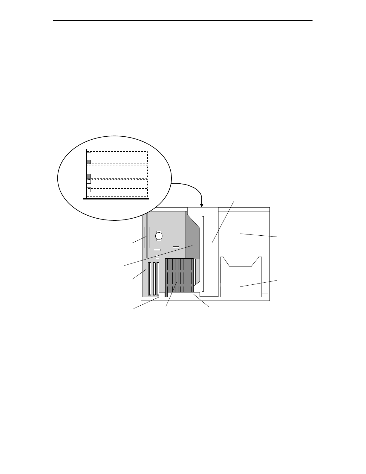
Chapter 2 System Overview
Compaq Deskpro EN Series of Personal Computers
Desktop and Minitower Form Factors
Third Edi tion – September 1998
2-6
2.3.2 CHASSIS LAYOUTS
Figures 2-4 and 2-5 show the layout of key assemblies within the desktop and minitower chassis
respectively. For serviceability this system features an expansion card cage that allows easy
removal of the backplane and expansion cards as a single assembly. The tilt drive cage tilts up for
easy removal/replacement of drives. For detailed information on servicing the chassis refer to the
multimedia training CD-ROM and/or the maintenance and service guide for this system.
Figure 2–4.
Desktop Chassis Layout, Top View
Front
Back
Power Supply
Tilt Drive Cage
System Board
Expansion Card Cage
Chassi s Fan
AGP NLX
Graphics Card
Processor
PCI Slot 4 (SCSI Card)
ISA Slot
PCI Slot 1 (NIC Card)
Slots On Backplane,
Rear View
PCI Slot 2
PCI Slot 3
ISA Slot
Wide-Ultra
SCSI Card
Speaker
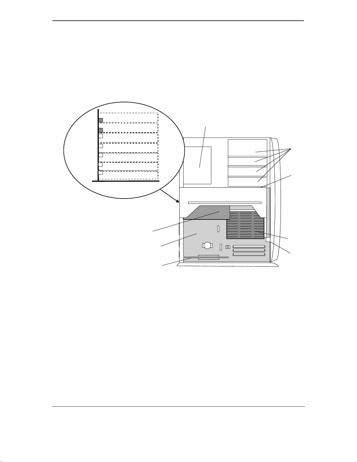
Technical Reference Guide
Compaq Deskpro EN Series of Personal Computers
Desktop and Minitower Form Factors
Third Edi tion - September 1998
2-7
Figure 2–5. Minit ower Chassis Layout, Left Side View
Front
Back
Power Supply
Drive Bays
System Board
Speaker
AGP NLX
Graphics Card
Processor
Wide-Ultra
SCSI Card
PCI Slot 1 (NIC Card)
Slots On Backplane,
Rear View @ 90
°
PCI Slot 3
PCI Slot 4
PCI Slot 5
ISA Slot
ISA Slot
Expansion Card Cage
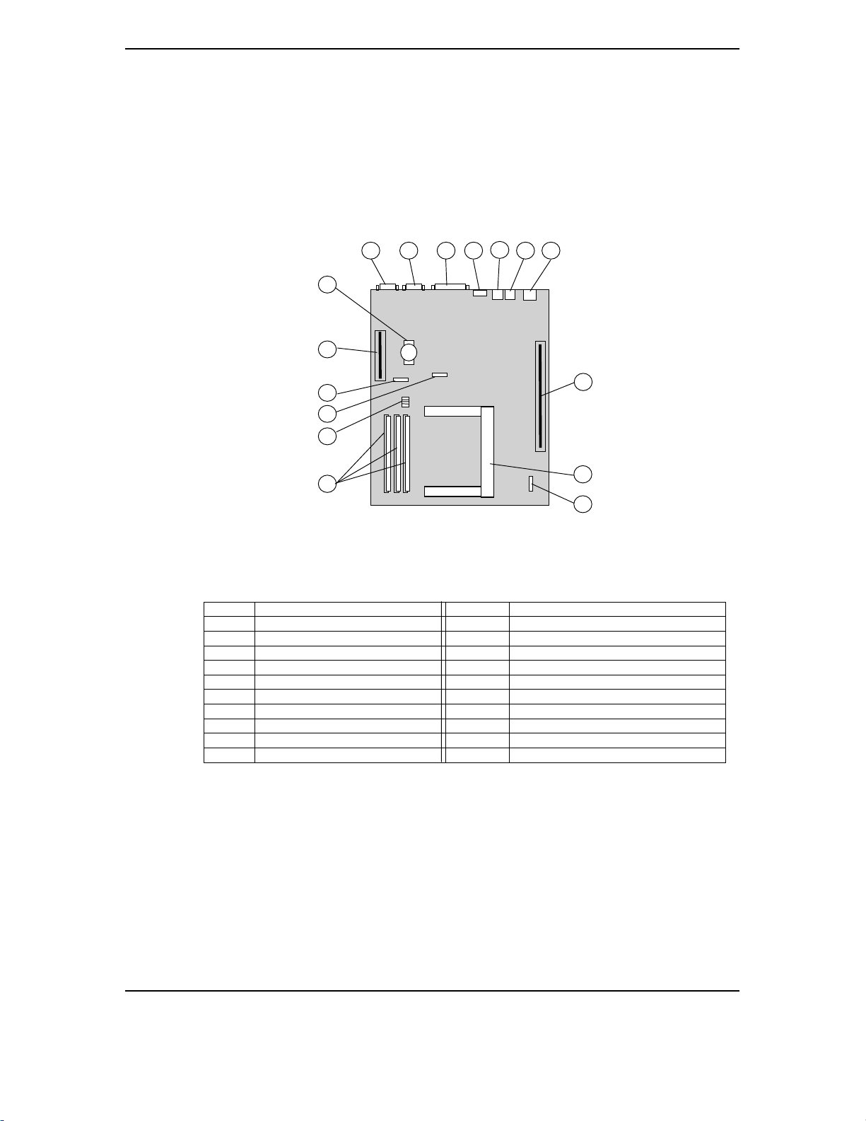
Chapter 2 System Overview
Compaq Deskpro EN Series of Personal Computers
Desktop and Minitower Form Factors
Third Edi tion – September 1998
2-8
2.3.3 BOARD LAYOUTS
Figure 2-6 shows the location of connectors and switches for the system board, which is the same
for all models and both formfactors.
Item Function Item Function
1 Serial I/F (COM2) 7 (bottom) USB Port A I/F
2 Serial I/F (COM1) 8 Backplane Connector
3 Parallel I/F 9 Processor Slot 1
4 (top) Mouse connector 10 Heat Sink Thermal Diode Connector [2]
4 (bottom) Keyboard connector 11 DIMM Sockets
5 (top) Audio Line Input 12 Frequency/Password DIP Switch
5 (bottom) Audio Line Output 13 Heat Sink Thermal Diode Connector [3]
6 (top) Audio Mic Input 14 CMOS Clear Jumper
6 (bottom) Audio Headphone Output 15 AGP Slot (NLX-type)
7 (top) USB Port B I/F 16 Battery
NOTE:
[1] T he two system boards are electrically identical. There are slight differences in the location of some
components. Later production units use the 008123-xxx board.
[2] PCA # 008123
[3] PCA # 007998
Figure 2–6.
System Board Connector and Switch Locations
System Board (NLX-Type)
1 3
4
5
2
8
9
6 7
(P/N 007998-xxx
or 008123-xxx [1])
11
12
13
14
15
16
10
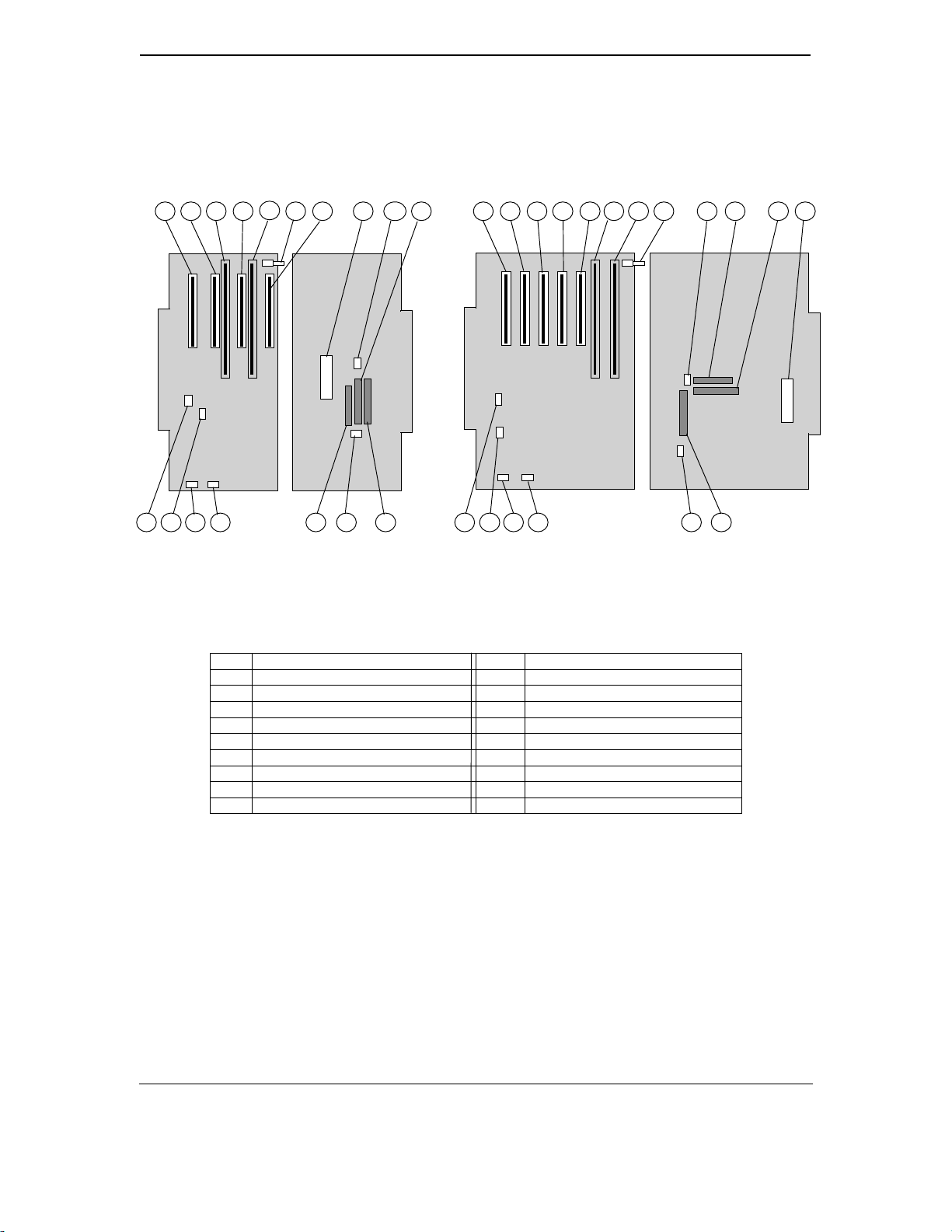
Technical Reference Guide
Compaq Deskpro EN Series of Personal Computers
Desktop and Minitower Form Factors
Third Edi tion - September 1998
2-9
Figure 2-7 shows the connector and switch locations for the two types of backplane boards.
Item Function Item Function
1 PCI connector J20 (slot 1) 10 CD audio input header P7
2 PCI connector J21 (slot 2) 11 Secondary EIDE connector P21
3 ISA connector J10 [1] 12 Diskette drive connector P10
4 PCI connector J22 (slot 3) [2] 13 Primary EIDE connector P20
5 ISA connector J11 [3] 14 Power button/LED header P5
6 Smart Cover sensor switch 15 Fan header P8
7 PCI connector J23 (slot 4) [4] 16 Speaker header P6
8 PCI connector J24 (slot 5) 17 SCSI LED header P29
9 Power supply connector P1 18 NIC WOL header P9
NOTES:
[1] Shares slot with item 4 on desktop backplane (combo slot 1)
[2] Shares slot with item 3 on desktop backplane (combo slot 1)
[3] Shares slot with item 7 on desktop backplane (combo slot 2)
[4] Shares slot with item 5 on desktop backplane (combo slot 2)
[5] Later production units use the 009663-001 board
Figure 2–7. Backplane Board Connector, Header, and Switch Locations
1 3
4
5
2 8
1312
11
9
15
10
16
1210
6 7
14
11
Desktop Backplane Boar d
(P/N 008001-xxx
or 009663-xxx [5])
System Board Side Power Supply Side
17
Power Supply SideSystem Board Side
Minitower Backplane Boar d
(P/N 008058-xxx)
1 2
4
7 3 5 9
18 131415161718
6
Loading...