


 Loading...
MAINTENANCE
& SERVICE GUIDE
Compaq Deskpro 2000
Series of Personal Computers
Pentium Processor with MMX Technology and Pentium II Processor
September 1997 Edition

278041-001
278785-002
Notice
The information in this guide is subject to change without notice.
COMPAQ COMPUTER CORPORATION SHALL NOT BE LIABLE FOR TECHNICAL OR EDITORIAL ERRORS OR OMISSIONS CONTAINED HEREIN; NOR FOR INCIDENTAL OR CONSEQUENTIAL DAMAGES RESULTING FROM THE FURNISHING, PERFORMANCE, OR USE OF THIS MATERIAL.
This guide contains information protected by copyright. No part of this guide may be photocopied or reproduced in any form without prior written consent from Compaq Computer Corporation.
© 1997 Compaq Computer Corporation. All rights reserved. Printed in the U.S.A.
Compaq, Deskpro
Registered U. S. Patent and Trademark Office.
Microsoft, MS-DOS, and Windows are registered trademarks of Microsoft Corporation.
The software described in this guide is furnished under a license agreement or nondisclosure agreement. The software may be used or copied only in accordance with the terms of the agreement.
Product names mentioned herein may be trademarks and/or registered trademarks of their respective companies.
Maintenance and Service Guide
Compaq Deskpro 2000 Series of Personal Computers Pentium Processor with MMX Technology
and Pentium II Processor
Second Edition (September 1997)
Part Number 278785-002
Spare Part Number 278041-001
Compaq Computer Corporation
CPS

CONTENTS
preface |
|
|
|
About this Guide |
|
|
|
Symbols and Conventions............................................................................................ |
ix |
||
Technician Notes........................................................................................................... |
x |
||
System Serial Number................................................................................................... |
x |
||
Locating Additional Information .................................................................................. |
x |
||
chapter 1 |
|
|
|
Product Description |
|
|
|
1.1 Compaq Deskpro 2000 Series of Personal Computer Models ........................... |
1-2 |
||
|
1.1.1 |
Desktop Models..................................................................................... |
1-2 |
|
1.1.2 |
Minitower Models ................................................................................. |
1-2 |
1.2 |
Features .............................................................................................................. |
1-3 |
|
|
1.2.1 |
Pentium System Feature Summary ....................................................... |
1-3 |
|
1.2.2 |
Pentium II System Feature Summary.................................................... |
1-3 |
|
1.2.3 |
Features Common to Both..................................................................... |
1-4 |
1.3 |
System Design.................................................................................................... |
1-5 |
|
|
1.3.1 |
Design Overview................................................................................... |
1-5 |
|
1.3.2 |
System Board ........................................................................................ |
1-6 |
|
1.3.3 |
Processor ............................................................................................... |
1-6 |
|
1.3.4 |
System Memory .................................................................................... |
1-6 |
|
1.3.5 |
Cache Memory ...................................................................................... |
1-6 |
|
1.3.6 |
Graphics Controllers ............................................................................. |
1-7 |
|
1.3.7 |
Chipsets ................................................................................................. |
1-7 |
|
1.3.8 |
System I/O............................................................................................. |
1-8 |
|
1.3.9 |
System BIOS ......................................................................................... |
1-8 |
|
1.3.10 |
Expansion Slots ..................................................................................... |
1-9 |
|
1.3.11 |
Power Supply ........................................................................................ |
1-9 |
|
1.3.12 |
Diskette Drive Interface ........................................................................ |
1-9 |
|
1.3.13 |
Serial Port .............................................................................................. |
1-9 |
|
1.3.14 |
Parallel Port ........................................................................................... |
1-9 |
|
1.3.15 |
System Security................................................................................... |
1-10 |
|
1.3.16 |
Keyboard/Mouse Controller................................................................ |
1-10 |
|
1.3.17 |
Real-Time Clock and CMOS RAM .................................................... |
1-10 |
|
1.3.18 |
Power Supply Fan ............................................................................... |
1-10 |
|
1.3.19 |
Speaker ................................................................................................ |
1-10 |
|
1.3.20 |
Software .............................................................................................. |
1-10 |
|
1.3.21 |
Ordering Additional Operating System Drivers.................................. |
1-11 |
|
1.3.22 |
Intelligent Manageability .................................................................... |
1-12 |
1.4 |
Desktop Computer Features ............................................................................. |
1-14 |
|
Contents iii

|
1.4.1 Front Panel Controls and LEDs .......................................................... |
1-14 |
|
|
1.4.2 |
Drive Positions .................................................................................... |
1-15 |
|
1.4.3 |
Rear Panel Connectors ........................................................................ |
1-16 |
1.5 |
Minitower Computer Features.......................................................................... |
1-17 |
|
|
1.5.1 Front Panel Lights and Controls.......................................................... |
1-17 |
|
|
1.5.2 |
Drive Positions .................................................................................... |
1-18 |
|
1.5.3 |
Rear Panel Connectors ........................................................................ |
1-20 |
1.6 |
Enhanced Keyboard ......................................................................................... |
1-22 |
|
1.7 |
Options |
............................................................................................................. |
1-24 |
|
1.7.1 |
Cache Upgrade .................................................................................... |
1-24 |
|
1.7.2 |
System Memory .................................................................................. |
1-24 |
|
1.7.3 |
Audio Upgrade .................................................................................... |
1-24 |
|
1.7.4 |
Mass Storage Options.......................................................................... |
1-24 |
|
1.7.5 |
Monitor Options .................................................................................. |
1-25 |
|
1.7.6 Graphics Controllers and Memory Options ........................................ |
1-25 |
|
|
1.7.7 |
Serial/Parallel Interface Board ............................................................ |
1-25 |
|
1.7.8 |
PD-CD Drive....................................................................................... |
1-26 |
|
1.7.9 |
Modems............................................................................................... |
1-26 |
chapter 2
Compaq Utilities
2.1 |
Getting Ready..................................................................................................... |
2-1 |
|
|
2.1.1 |
Preparing the Computer ........................................................................ |
2-1 |
|
2.1.2 Create a Diagnostics Diskette .............................................................. |
2-2 |
|
|
2.1.3 |
Accessing the Compaq Utilities Menu.................................................. |
2-2 |
2.2 |
Computer Setup.................................................................................................. |
2-3 |
|
|
2.2.1 |
Security Features ................................................................................... |
2-5 |
|
2.2.2 |
QuickLock/QuickBlank ........................................................................ |
2-9 |
2.3 |
Computer Checkup (TEST) ............................................................................. |
2-10 |
|
2.4 |
View System Information (INSPECT)............................................................. |
2-11 |
|
2.5 |
Create a Diagnostics Diskette........................................................................... |
2-12 |
|
2.6 |
Managing the Diagnostics Partition ................................................................. |
2-12 |
|
2.7 |
Exiting the Compaq Utilities Menu ................................................................. |
2-13 |
|
2.8 |
Compaq Enhanced Insight Personal Edition (Diagnostics for Windows)........ |
2-13 |
|
2.9 |
Power-On Self-Test (POST) ............................................................................ |
2-13 |
|
2.10 ROMPaq........................................................................................................... |
2-14 |
||
2.11 Compaq Intelligent Manageability................................................................... |
2-15 |
||
|
2.11.1 Asset Management .............................................................................. |
2-15 |
|
|
2.11.2 Fault Management............................................................................... |
2-16 |
|
|
2.11.3 Security Management.......................................................................... |
2-17 |
|
|
2.11.4 Configuration Management................................................................. |
2-18 |
|
|
2.11.5 Integration Management ..................................................................... |
2-24 |
|
2.12 Protecting Your Software................................................................................. |
2-26 |
||
|
2.12.1 Ordering Backup Diskettes ................................................................. |
2-26 |
|
|
2.12.2 Restoring Your Hard Drive in Windows 95........................................ |
2-27 |
|
2.13 Prefailure Warranty .......................................................................................... |
2-27 |
||
iv Contents

chapter 3
Illustrated Parts Catalog
3.1 |
System Unit ........................................................................................................ |
3-2 |
3.2 |
Mass Storage Devices ........................................................................................ |
3-6 |
3.3 |
Cables ................................................................................................................. |
3-8 |
3.4 |
Standard and Optional Boards.......................................................................... |
3-10 |
3.5 |
Keyboards......................................................................................................... |
3-14 |
3.6 |
Monitors ........................................................................................................... |
3-16 |
3.7 |
Miscellaneous Hardware Kit ............................................................................ |
3-19 |
3.8 |
Miscellaneous Plastics Kit ............................................................................... |
3-20 |
3.9 |
Miscellaneous Parts.......................................................................................... |
3-22 |
3.10 Shipping Boxes ................................................................................................ |
3-24 |
|
3.11 Documentation ................................................................................................. |
3-25 |
|
3.12 Software ........................................................................................................... |
3-26 |
|
chapter 4
Removal and Replacement Prelinimaries
4.1 |
Electrostatic Discharge Information................................................................... |
4-1 |
|
|
4.1.1 |
Generating Static ................................................................................... |
4-1 |
|
4.1.2 Preventing Electrostatic Damage to Equipment.................................... |
4-2 |
|
|
4.1.3 |
Personal Grounding Methods................................................................ |
4-2 |
|
4.1.4 |
Grounding Workstations ....................................................................... |
4-3 |
|
4.1.5 |
Personal Grounding Equipment ............................................................ |
4-3 |
|
4.1.6 Recommended Materials and Equipment.............................................. |
4-3 |
|
4.2 |
Routine Care....................................................................................................... |
4-4 |
|
|
4.2.1 General Cleaning Safety Precautions .................................................... |
4-4 |
|
|
4.2.2 Cleaning the Computer Case................................................................. |
4-4 |
|
|
4.2.3 |
Cleaning the Keyboard.......................................................................... |
4-5 |
|
4.2.4 |
Cleaning the Monitor ............................................................................ |
4-5 |
|
4.2.5 |
Cleaning the Mouse............................................................................... |
4-5 |
4.3 |
Service Considerations ....................................................................................... |
4-6 |
|
|
4.3.1 Tools and Software Requirements ........................................................ |
4-6 |
|
|
4.3.2 |
Screws ................................................................................................... |
4-6 |
|
4.3.3 |
Cables and Connectors .......................................................................... |
4-6 |
|
4.3.4 |
Hard Drives ........................................................................................... |
4-7 |
|
4.3.5 |
Plastic Parts ........................................................................................... |
4-7 |
|
4.3.6 |
Lithium Battery ..................................................................................... |
4-7 |
chapter 5
Removal and Replacement Procedures - Desktop
5.1 |
Serial Number .................................................................................................... |
5-1 |
5.2 |
Disassembly Sequence Chart ............................................................................. |
5-2 |
5.3 |
Preparation for Disassembly .............................................................................. |
5-3 |
5.4 |
Feet ..................................................................................................................... |
5-4 |
5.5 |
Cable Lock ......................................................................................................... |
5-5 |
5.6 |
System Unit Cover ............................................................................................. |
5-6 |
5.7 |
Speaker ............................................................................................................... |
5-7 |
5.8 |
Expansion Board ................................................................................................ |
5-9 |
|
5.8.1 Inboard Expansion Board.................................................................... |
5-10 |
Contents v

|
5.8.2 |
Outboard Expansion Board ................................................................. |
5-11 |
5.9 |
System Board Components ............................................................................. |
5-12 |
|
|
5.9.1 |
Memory Modules ................................................................................ |
5-12 |
|
5.9.2 System Board Graphics Memory Module Upgrade ............................ |
5-13 |
|
|
5.9.3 |
Microprocessor.................................................................................... |
5-14 |
|
5.9.4 Cache Memory (Pentium System Only) ............................................. |
5-17 |
|
5.10 |
Riser Board ..................................................................................................... |
5-18 |
|
5.11 |
Riser Brace ...................................................................................................... |
5-19 |
|
5.12 |
Expansion Board Guide .................................................................................. |
5-20 |
|
5.13 |
Replacement Battery ....................................................................................... |
5-21 |
|
5.14 |
Front Bezel Assembly ..................................................................................... |
5-23 |
|
|
5.14.1 |
Front Bezel ......................................................................................... |
5-23 |
|
5.14.2 |
Power Button...................................................................................... |
5-24 |
|
5.14.3 |
Bezel Blank ........................................................................................ |
5-25 |
|
5.14.4 |
Compaq Logo..................................................................................... |
5-26 |
5.15 |
Power Supply Assembly ................................................................................. |
5-27 |
|
|
5.15.1 |
Power Switch Assembly..................................................................... |
5-27 |
|
5.15.2 |
Power Supply ..................................................................................... |
5-29 |
5.16 |
Mass Storage Devices ..................................................................................... |
5-30 |
|
|
5.16.1 |
3.5-Inch Drive Bays ........................................................................... |
5-30 |
|
5.16.2 |
5.25-Inch Drive Bays ......................................................................... |
5-32 |
|
5.16.3 Installing a New Drive ....................................................................... |
5-34 |
|
5.17 |
Drive Cage ...................................................................................................... |
5-37 |
|
5.18 |
LED Cable....................................................................................................... |
5-38 |
|
5.19 |
System Board .................................................................................................. |
5-40 |
|
chapter 6
Removal and Replacement Procedures - Minitower
6.1 |
Serial Number ................................................................................................... |
6-1 |
|
6.2 |
Disassembly Sequence Chart ............................................................................ |
6-2 |
|
6.3 |
Preparation for Disassembly ............................................................................. |
6-3 |
|
6.4 |
Feet .................................................................................................................... |
|
6-3 |
6.5 |
Cable Lock ........................................................................................................ |
6-4 |
|
6.6 |
Exposing the Chassis......................................................................................... |
6-5 |
|
|
6.6.1 |
Access Panel......................................................................................... |
6-5 |
|
6.6.2 |
Minitower J Hood................................................................................. |
6-6 |
6.7 |
Riser Brace ........................................................................................................ |
6-7 |
|
6.8 |
Expansion Board ............................................................................................... |
6-8 |
|
6.9 |
Expansion Board Guide .................................................................................. |
6-10 |
|
6.10 |
Riser Board ..................................................................................................... |
6-11 |
|
6.11 |
Speaker |
............................................................................................................ |
6-12 |
6.12 System Board Components ............................................................................. |
6-13 |
||
|
6.12.1 |
Memory Module................................................................................. |
6-13 |
|
6.12.2 |
Microprocessor................................................................................... |
6-14 |
|
6.12.3 Cache Memory (Pentium System Only) ............................................ |
6-17 |
|
|
6.12.4 System Board Graphics Memory Module Upgrade ........................... |
6-18 |
|
6.13 System Board .................................................................................................. |
6-19 |
||
6.14 |
Replacement Battery ....................................................................................... |
6-22 |
|
6.15 ISA Option Board Retainer ............................................................................. |
6-24 |
||
vi Contents

6.16 |
Front Bezel Assembly..................................................................................... |
6-25 |
|
6.16.1 Front Bezel .......................................................................................... |
6-25 |
|
6.16.2 Power Button....................................................................................... |
6-26 |
|
6.16.3 Bezel Blank ......................................................................................... |
6-27 |
|
6.16.4 Compaq Logo...................................................................................... |
6-28 |
6.17 |
Power Supply Assembly................................................................................. |
6-29 |
|
6.17.1 Power Supply Switch Assembly ......................................................... |
6-29 |
|
6.17.2 Power Supply ...................................................................................... |
6-31 |
6.18 |
LED Cable ...................................................................................................... |
6-32 |
6.19 |
Mass Storage Devices..................................................................................... |
6-34 |
|
6.19.1 3.5-Inch Drive Bays ............................................................................ |
6-34 |
|
6.19.2 5.25-Inch Drive Bays .......................................................................... |
6-36 |
|
6.19.3 Installing a New Drive ........................................................................ |
6-38 |
chapter 7
Jumper and Switch Information
7.1 |
System Board Switches ...................................................................................... |
7-2 |
|
|
7.1.1 |
Pentium-Based System Boards ............................................................. |
7-2 |
|
7.1.2 |
Switch Settings ...................................................................................... |
7-5 |
7.2 |
System Board Jumpers ....................................................................................... |
7-6 |
|
|
7.2.1 Setting Power-On Password Jumpers.................................................... |
7-7 |
|
|
7.2.2 |
Clearing Configuration.......................................................................... |
7-8 |
|
7.2.3 Changing the Real-Time Clock (RTC) Battery..................................... |
7-9 |
|
7.3 |
Hard Drives ...................................................................................................... |
7-10 |
|
|
7.3.1 2.1-GB EIDE Hard Drive Jumper Settings ......................................... |
7-10 |
|
|
7.3.2 3.2-GB EIDE Hard Drive Jumper Settings ......................................... |
7-12 |
|
|
7.3.3 Optional Ultra SCSI Hard Drive Jumper Settings............................... |
7-14 |
|
|
7.3.4 Optional Ultra ATA Hard Drives Jumper Settings ............................. |
7-16 |
|
7.4 |
CD-ROM Drive Jumper Settings ..................................................................... |
7-18 |
|
7.5 |
Optional PD-CD Drives ................................................................................... |
7-18 |
|
|
7.5.1 SCSI PD-CD Drive Jumper Settings................................................... |
7-18 |
|
7.6 |
Diskette Drive .................................................................................................. |
7-19 |
|
chapter 8
Specifications
8.1 |
System ................................................................................................................ |
8-1 |
8.2 |
Drives ................................................................................................................. |
8-7 |
8.3 |
Audio System ................................................................................................... |
8-14 |
8.4 |
Keyboard .......................................................................................................... |
8-14 |
8.5 |
Mouse ............................................................................................................... |
8-15 |
8.6 |
Supported Graphics Resolutions ...................................................................... |
8-15 |
Contents vii

appendix A |
|
Connector Pin Assignments......................................................................................................... |
A-1 |
appendix B |
|
Power Cord Set Requirements |
|
General Requirements............................................................................................... |
B-1 |
Country-Specific Requirements ................................................................................ |
B-2 |
appendix C |
|
Hard Drives |
|
Device 0/Device 1 Relationship................................................................................ |
C-1 |
Cable Select............................................................................................................... |
C-1 |
SMART ..................................................................................................................... |
C-2 |
Automatic Soft-Drive Types ..................................................................................... |
C-2 |
appendix D |
|
SCSI Guidelines ............................................................................................................................ |
D-1 |
appendix E |
|
Diagnostic Error Codes |
|
SCSI Error Codes....................................................................................................... |
E-9 |
appendix F |
|
POST Error Messages................................................................................................................... |
F-1 |
appendix G |
|
Troubleshooting Without Diagnostics |
|
Checklist for Solving Minor Problems ..................................................................... |
G-1 |
Power Problems ........................................................................................................ |
G-2 |
Diskette Drive Problems ........................................................................................... |
G-3 |
Display Problems ...................................................................................................... |
G-4 |
Printer Problems........................................................................................................ |
G-5 |
Hard Drive Problems................................................................................................. |
G-6 |
Hardware Installation Problems ................................................................................ |
G-7 |
CD-ROM Drive Problems......................................................................................... |
G-8 |
Memory Problems..................................................................................................... |
G-9 |
SCSI Problems .......................................................................................................... |
G-9 |
Network Problems................................................................................................... |
G-10 |
Resolving Audio Hardware Conflicts ..................................................................... |
G-12 |
appendix H |
|
Intel 440LX Chipset Memory Limitations .................................................................................... |
H-1 |
Index ............................................................................................................................................... |
I-1 |
viii Contents
preface
ABOUT THIS GUIDE
This Maintenance and Service Guide is a troubleshooting and repair guide that can be used for reference when servicing the Compaq Deskpro 2000 Series of Personal Computers. Only authorized technicians trained by Compaq should attempt to repair this equipment.
Compaq Computer Corporation reserves the right to make changes to the Compaq Deskpro 2000 Series of Personal Computers without notice.
Symbols and Conventions
The following text and symbols mark special messages throughout this guide:
!in bodily harm or loss of life.
CAUTION: Text set off in this manner indicates that failure to follow directions could result in damage to equipment or loss of data.WARNING: Text set off in this manner indicates that failure to follow directions in the warning could result
Text set off in this manner presents commentary, sidelights, clarifying information, or specific instructions.
The following format conventions distinguish elements of the text throughout this guide:
„ Drive letters that are not in command lines are presented in uppercase type as shown here: drive A.
„ Directory or folder names that are not in command lines are presented in uppercase type as shown here: DIRECTORY or FOLDER.
„ The file names are presented in uppercase italic type as shown here: FILENAME.
„ The names of commands are presented in lowercase as shown here: install or a:\install.
„ Commands that are to be entered at the system prompt may be shown on a separate line:
a:install
„ When you need to type information without pressing Enter, you are directed to “type” the information.
„ When you need to type the information and press Enter, you are directed to “enter” the information.
Preface ix

Technician Notes
!troubleshooting and repair procedures are detailed to allow only subassembly/module level repair. Because of the complexity of the individual boards and subassemblies, no one should attempt to make repairs at the component level or to make modifications to any printed wiring board, Improper repairs can create a safety hazard. Any indications of component replacement or printed wiring board modifications may void any warranty.
CAUTION: To properly ventilate your system, you must provide at least 3-inches (7.62-cm) of clearance at the front and back of the computer.
CAUTION: The computer is designed to be electrically grounded, To ensure proper operation, plug the AC power cord into a properly grounded AC outlet only.WARNING: Only authorized technicians trained by Compaq should attempt to repair this equipment. All
System Serial Number
The location of the serial number for the desktop computer is found in Chapter 5 and for the minitower computer in Chapter 6 in this guide.
For the purpose of AssetControl, the serial number is embedded in the CMOS on the system board.
Locating Additional Information
The following documentation is available to support these products:
„ User Documentation
„ Technical Training Guides
„ Compaq Service Advisories and Bulletins
„ Compaq QuickFind
„ Technical Reference Guide
„ Compaq Service Quick Reference Guide
„ Compaq SmartStart for Workstations CD online documentation
x Preface
chapter 1
PRODUCT DESCRIPTION
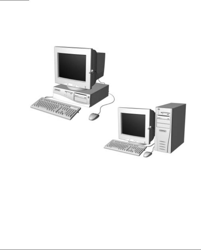
This chapter describes the model offerings and features of the Compaq Deskpro 2000 Series of Personal Computers.
Figure 1-1. Compaq Deskpro 2000 Series Personal Computer
Compaq Deskpro 2000 Series of Personal Computers |
1-1 |

1.1Compaq Deskpro 2000 Series of Personal Computer Models
The Compaq Deskpro 2000 Series of Personal Computers is available in both desktop and minitower configurations. This series of personal computers uses the Intel family of Pentium processors consisting of the Intel Pentium processor and the Intel Pentium II processor. Both processors utilize MMX technology. These configurations are described in the following sections.
1.1.1Desktop Models
Table 1-1
Desktop Models
Configuration |
|
|
|
|
Maximum |
Internal |
|
Code |
Processor |
Hard Drive |
CD-ROM |
Memory |
Memory |
Cache |
Graphics |
|
|
|
|
|
|
|
|
Pentium Processor |
|
|
|
|
|
|
|
BK52 |
P55C/166 |
2.1-GB |
|
16-MB |
384-MB |
256K |
S3 Trio64V2/GX |
BK53 |
P55C/166 |
2.1-GB |
16X |
32-MB |
384-MB |
256K |
S3 Trio64V2/GX |
BK54 |
P55C/166 |
3.2-GB |
|
32-MB |
384-MB |
256K |
S3 Trio64V2/GX |
BK55 |
P55C/166 |
3.2-GB |
|
16-MB |
384-MB |
256K |
S3 Trio64V2/GX |
BK62 |
P55C/200 |
2.1-GB |
|
16-MB |
384-MB |
256K |
S3 Trio64V2/GX |
BK63 |
P55C/200 |
3.2-GB |
16X |
32-MB |
384-MB |
256K |
S3 Trio64V2/GX |
BK64 |
P55C/200 |
3.2-GB |
|
32-MB |
384-MB |
256K |
S3 Trio64V2/GX |
BNT2 |
P55C/233 |
3.2-GB |
16X |
32-MB |
384-MB |
256K |
S3 Trio64V2/GX |
Pentium II Processor |
|
|
|
|
|
|
|
BMJ2 |
PII/233 |
2.1-GB |
|
32-MB |
384-MB |
512K |
Matrox MGA-1064SG |
BMK2 |
PII/233 |
3.2-GB |
24X |
32-MB |
384-MB |
512K |
Matrox MGA-1064SG |
BML2 |
PII/266 |
3.2-GB |
24X |
32-MB |
384-MB |
512K |
Matrox MGA-1064SG |
Some models may not be available in all countries.
1.1.2Minitower Models
Table 1-2
Minitower Models
Configuration |
|
|
|
|
Maximum |
Internal |
|
Code |
Processor |
Hard Drive |
CD-ROM |
Memory |
Memory |
Cache |
Graphics |
|
|
|
|
|
|
|
|
Pentium Processor |
|
|
|
|
|
|
|
BK72 |
P55C/166 |
3.2-GB |
16X |
32-MB |
384-MB |
256K |
S3 Trio64V2/GX |
BK82 |
P55C/200 |
3.2-GB |
16X |
32-MB |
384-MB |
256K |
S3 Trio64V2/GX |
Pentium II Processor |
|
|
|
|
|
|
|
BMM2 |
PII/266 |
3.2-GB |
24X |
32-MB |
384-MB |
512K |
Matrox MGA-1064SG |
BR32 |
PII/300 |
3.2-GB |
24X |
32-MB |
384-MB |
512K |
Matrox MGA-1064SG |
Some models may not be available in all countries.
1-2 Product Description

1.2 Features
The Compaq Deskpro 2000 Series of Personal Computers have the following standard features:
1.2.1Pentium System Feature Summary
■Intel Pentium Processor with MMX technology running at speeds of 166, 200, and 233 megahertz
■256-KB (L2) cache secondary standard, expandable to 512-KB
■16or 32-megabyte synchronous dynamic random access memory (SDRAM) standard depending on the model, expandable to 384 megabytes of SDRAM installed in dual inline memory modules (DIMMs)
■One Enhanced IDE (EIDE) SMART II hard drive installed
■One 16X Max EIDE CD-ROM drive, Compaq Business Pro 16-bit audio board, and an enhanced speaker installed on select models
■S3 Trio64V2/GX enhanced 64-bit graphics controller with 1 MB of memory installed on the system board, expandable to 2 megabytes
■Microsoft Windows 95 operating system software
1.2.2Pentium II System Feature Summary
■Intel Pentium II Processor with MMX technology running at speeds of 233, 266, and 300 megahertz
■One Ultra ATA (ultra direct memory access or UDMA) SMART II hard drive installed
■32-megabyte SDRAM standard, expandable to 384 megabytes of SDRAM installed in dual inline memory modules (DIMMs)
■512-KB (L2) cache secondary standard, not upgradable
■One 24X Max EIDE CD-ROM drive, Compaq Business Pro 16-bit audio board, and an enhanced speaker installed on select models
■Matrox MGA-1064SG graphics accelerator controller with 2 MB of synchronous graphics random access memory (SGRAM) installed on the system board, expandable to 4 MB
■Microsoft Windows NT 4.0 operating system software
Compaq Deskpro 2000 Series of Personal Computers |
1-3 |

1.2.3Features Common to Both
One 1.44-megabyte, 3.5-inch high-density diskette drive installed
Peripheral Components Interconnect (PCI) chipset used for PCI/ISA, two USB ports, memory, and peripheral control
Super I/O controller which integrates a serial port, parallel port, diskette drive interface, realtime clock, CMOS RAM, and mouse and keyboard controller
PCI and ISA peripheral connectors on the expansion riser board
BIOS in a flash memory device which supports PCI auto-configuration
Desktop chassis, including expansion slots for up to five expansion boards
Two dedicated half-length PCI slots
Two dedicated ISA-bus slots (one half-length and one full-length)
One full-length "combination" slot for either a PCI or an ISA expansion board
Surge-tolerant continuous power supply, switch-selectable for 115 and 230 VAC operation
Minitower chassis, including expansion slots for up to five expansion boards
Two dedicated full-length PCI slots
Two dedicated full-length ISA-bus slots
One full-length "combination" slot for either a PCI or an ISA expansion board
Surge-tolerant continuous power supply, switch-selectable for 115 and 230 VAC operation
One RS-232C compatible 9-pin serial connector
One multimode, 25-pin enhanced parallel connector
Two Universal Serial Bus (USB) connectors on all models
Five drive bays on desktop models:
One external 3.5-inch, one-third height diskette drive bay
One internal 3.5-inch, one-third height drive bay
Two external 5.25-inch, one-half height drive bays or one full-height drive
One internal 5.25-inch one-third height hard drive bay
Five drive bays on minitower models:
One external 3.5-inch, one-third height diskette drive bay
One internal 3.5-inch, one-third height drive bay
Three external 5.25-inch, one-half height drive bays
Compaq Business Pro 16-bit audio board and an enhanced speaker installed on select models
Hard drive fault protection standard on all SMART II hard drives
Compaq Enhanced Keyboard, featuring the Microsoft Windows–specific keys
1-4 Product Description

■Mouse
■Keyboard and mouse connectors on the back panel
■Internal piezo speaker mounted on system board
■Intelligent Manageability and security features, including password and cable lock provision
■Compaq Diagnostics and Configuration utilities, support software, and device drivers
1.3System Design
This section presents a design overview and functional descriptions of the key components of the Compaq Deskpro 2000 Series of Personal Computers. All replaceable components are identified in Chapter 3, and removal/replacement instructions are presented in Chapters 5 and 6.
1.3.1Design Overview
The desktop models of the Compaq Deskpro 2000 Series of Personal Computers have a conventional design that uses a pan-type chassis to house the system board, expansion cards, power supply, and mass storage devices. The chassis is supplemented by a riser board attached to the riser brace. The riser board provides a mounting location for the expansion cards.
All internal components are accessible when the hood, held in place by two thumbscrews, is removed. The front bezel is mounted to the front of the chassis. Torx T-15 screws are used throughout the system.
The system board is easily removed from the side of the chassis after the hood and riser board are removed. Details of the disassembly procedure for desktop models are found in Chapter 5, “Removal and Replacement Procedures.”
The riser board mounts perpendicularly to the system board. Expansion boards are installed horizontally into the riser board. A single screw attaches each expansion board to the rear panel of the chassis.
The power supply is mounted in the right rear corner of the chassis. The power supply is held in place by three Torx screws that are installed through the rear panel of the chassis.
The minitower models have a chassis designed to house the system board, riser board, option cards, power supply, and mass storage devices. The use of a riser brace to hold the riser board, and any expansion boards installed, allows for easy access to the system board. The power supply is mounted in the top of the unit.
All internal components are immediately accessible when the side panel is removed.
The minitower’s tray-mounted system board is easily removed after taking off the side panel and riser brace. Details of the disassembly procedure for minitower models are found in Chapter 6, “Removal and Replacement Procedures.”
Detailed descriptions of the system components are presented in the sections that follow.
Compaq Deskpro 2000 Series of Personal Computers |
1-5 |

1.3.2System Board
The desktop and minitower models of the Compaq Deskpro 2000 Series of Personal Computers have a single system board configuration. The Pentium system board uses an Intel Pentium processor. The Pentium II system board uses the Intel Pentium II processor. The processors are designed using MMX technology. The desktop units of both systems have the I/O panel mounted to the system board and is spared with the I/O panel. On the minitower, the system board is attached to a sliding tray and is spared with the tray.
1.3.3Processor
The Pentium system boards run at processor speeds of 166 MHz, 200 MHz, or 233 MHz depending on the model. A computer with a processor speed of 166 MHz can be upgraded to a processor speed of either 200 MHz or 233 MHz. A computer with processor speed 200 MHz can be upgraded to a processor speed of 233 MHz.
The Pentium II system boards run at speeds of 233 MHz, 266 MHz, or 300 MHz. A Pentium II system with a processor speed of 233 MHz can be upgraded to a processor speed of either 266 MHz or 300 MHz, and a Pentium II system with a processor speed 266 MHz can be upgraded to a processor speed of 300 MHz.
Utilizing MMX technology in the design of the processors enhances the systems’ ability to take advantage of the MMX instructions while preserving compatibility with existing software and operating systems
1.3.4System Memory
The system supports base (conventional) and extended memory. Operating systems such as MS-DOS, OS/2, UNIX, and all application programs use base memory. For better performance, Windows NT, OS/2, and UNIX, as well as many MS-DOS applications, use extended memory.
For proper system operation, the DIMMs must be industry standard 168-pin, 66-MHz or faster unbuffered SDRAM DIMMs. The memory modules may also be unbuffered extended data out (EDO) DIMMs. SDRAM DIMMs must support CAS Latency 2 or 3 (CL = 2 or CL = 3) with a data access time (clock to data out) of 9.0 ns or less. The DIMMs must also contain Joint Electron Device Engineering Council (JEDEC) Serial Presence Detect (SPD) information. SDRAMS on DIMMs must have a data width of x8, x16, or x32; x4 is not supported. The system will not start using unsupported DIMMs or incompatible DIMM configurations. See Appendix H, “Intel 440LX Chipset Memory limitations,” for incompatible and unsupported DIMM configurations. Refer to Chapters 5 and 6, “Removal and Replacement Procedures,” for information on how to upgrade system memory.
1.3.5Cache Memory
Cache memory is very fast memory used for temporarily storing data for fast access by the processor. The faster the processor, the more need there is for faster temporary data storage. A 256 KB writethrough, direct-mapped secondary (L2) cache is integrated onto the system board on all Pentium models. The L2 cache memory for the Pentium models may be increased to 512 KB with the addition of an optional plug-in module on the system board.
1-6 Product Description

L2 cache memory for all Pentium II models is integrated in the processor module with a capacity of 512 KB and is not upgradable.
1.3.6Graphics Controllers
The purpose of a graphics controller is to generate the text and graphics images for the monitor screen. The quality of the picture you see depends on the resolution of the monitor, the number of colors the graphics controller can display, and the amount of graphics memory available. High resolution graphics with many colors require that the graphics controller have its own memory system.
The Pentium computers come with the S3 Trio64V2/GX Enhanced 64-bit graphics controller integrated onto the system board and have 1 MB of SGRAM installed. Graphics memory on these models may be upgraded to 2 MB with the addition of an optional memory module.
The Pentium II computer comes with the Matrox MGA-1064SG graphics accelerator integrated onto the system board and has 2 MB of SGRAM installed. Graphics memory on these models may be upgraded to 4 MB with the addition of an optional memory module.
Supported screen resolutions for the controller are listed in Chapter 8, “Specifications.”
1.3.7Chipsets
VIA Chipset
The Pentium system uses the VIA Apollo VP2/AMD-640 chipset. This provides a high-speed, 32-bit PCI/IDE (EIDE) interface, which supports the following:
■Up to four PCI/IDE (EIDE) devices on the PCI bus
■SDRAM and EDO DIMM support
■ECC DIMM support
440LX Chipset
The Intel 440LX chipset is designed specifically for the Pentium II system. This provides support for the latest technologies, including the following:
■Up to four PCI/IDE (EIDE) devices on the PCI bus or four Ultra ATA devices
■Ultra ATA Mode 2 support
■SDRAM and EDO DIMM support
■ECC DIMM support
Compaq Deskpro 2000 Series of Personal Computers |
1-7 |

1.3.8System I/O
The onboard I/O controller integrates the functions for the serial and parallel ports, diskette drives, the keyboard and mouse. This component provides support for the following:
■Multimode bidirectional parallel port
Standard mode: Centronics-compatible operation
High-speed mode with support for an enhanced capabilities port (ECP) and enhanced parallel port (EPP)
■One RS-232C compatible 9-pin serial port
■Integrated real-time clock
■242-byte, battery-backed CMOS RAM
■Integrated 8042-compatible keyboard controller
■Industry-standard diskette drive controller that supports 360-kilobyte and 1.2-megabyte 5.25-inch drives
1.3.9System BIOS
The system BIOS provides ISA and PCI compatibility. Contained in a flash memory device on the system board, the BIOS provides both the Power-On Self-Test (POST) and PCI and EIDE autoconfiguration utilities.
The system BIOS is always “shadowed.” Shadowing allows any BIOS routines to be executed from fast 64-bit onboard DRAM instead of from the slower 8-bit flash device.
PCI Auto-Configuration
The PCI auto-configuration utility works in conjunction with the Setup program to support using PCI expansion boards in the system. When you turn on the computer power after installing a PCI board, the BIOS automatically configures interrupts, I/O space, and PCI devices. If problems arise or you wish to reconfigure the device, refer to Chapter 2, “Compaq Utilities,” which explains how to use the Setup program. The PCI auto-configuration program complies with version 2.1 of the PCI BIOS specification.
IDE/EIDE Auto-Configuration
If you install an IDE/EIDE drive into the computer, the IDE/EIDE auto-configuration utility automatically detects and configures the drive for operation in the computer. This utility eliminates the need to run the Setup program after you install an IDE/EIDE drive.
ISA Plug and Play Capability
ISA Plug and Play capability provides auto-configuration of Plug and Play ISA boards and resource management for legacy (non–Plug and Play) ISA boards when used with Computer Setup or a Plug and Play–compatible operating system like Microsoft’s Windows 95.
1-8 Product Description
BIOS Upgrades
Because the BIOS is stored in a flash memory device, you can easily upgrade the BIOS without having to disassemble the system. The flash upgrade process can be accomplished by running a utility from a diskette, a hard drive, or over a network.
The section on Flash ROM in Chapter 2, “Compaq Utilities,” explains how to run the BIOS upgrade utility.
1.3.10 Expansion Slots
The computer has two dedicated 16-bit ISA-compatible slots, two dedicated PCI-compatible expansion slots, and one “combination slot” that can be used by either a PCI or an ISA board. For more information about expansion slots and installing expansion boards, see Chapters 5 and 6, “Removal and Replacement Procedures.”
1.3.11 Power Supply
The power supply provides power for system requirements including onboard resources, expansion boards, and drives. The desktop system supports a maximum of 145-watts of continuous power. The minitower system supports a maximum of 185-watts of continuous power. The same power supply, rated at 200-watts maximum output, provides for both system requirements. The power supply has integrated surge protection to withstand a 2,000 volt power surge. A switch on the computer back panel sets the power supply to operate at:
■115 VAC (in the range of 100-120 VAC)
■230 VAC (in the range of 200-240 VAC)
1.3.12Diskette Drive Interface
The diskette drive interface is 8477 compatible and supports two storage devices (diskette or tape drive).
1.3.13 Serial Port
The serial port is RS-232C compatible.
1.3.14 Parallel Port
The following parallel support modes are supported:
■Bidirectional Standard Parallel Port (SPP)
■Enhanced Parallel Port (EPP)
■Extended Capabilities Port (ECP)
Compaq Deskpro 2000 Series of Personal Computers |
1-9 |

1.3.15 System Security
The system BIOS provides a power-on password option that is enabled through the Setup program. The computer includes a cable lock provision that makes it possible to lock the computer cover in place to prevent unauthorized access to the system jumpers and other internal components (a padlock is not included). For more information on this and additional security features, refer Chapter 2, “Compaq Utilities.”
1.3.16 Keyboard/Mouse Controller
The onboard 8042 I/O controller stores the keyboard and mouse controller code. Connectors for the keyboard and mouse are located on the back panel.
1.3.17 Real-Time Clock and CMOS RAM
The onboard I/O controller provides a real-time clock and CMOS RAM. Chapters 5 and 6, “Removal and Replacement,” provide information about installing a new battery.
You can set the time for the clock and the CMOS values by using the Setup program described in Chapter 2, “Compaq Utilities.”
1.3.18 Power Supply Fan
For cooling, a fan is incorporated as part of the power supply at the rear of the computer chassis. The fan draws air in through the front of the chassis and exhausts air out the rear of the chassis. This provides adequate air flow across the processor.
To insure that the processor in a Pentium II minitower system receives adequate ventilation, an internal air duct is installed in the front of the unit.
1.3.19 Speaker
An internal piezo speaker is mounted on the system board. The speaker provides audible error code information (beep codes) during the Power-On Self-Test (POST) and as required by the software. See Appendix F, “POST Error Messages,” for beep code information.
1.3.20 Software
The Pentium computer configurations are shipped with Windows 95 installed as the operating system. The Pentium II configurations ship with Windows NT 4.0 as the operating system.
Preloaded Software
The following Compaq software is preloaded on the computer:
■Partition-based Compaq Diagnostics utilities
■Compaq Diagnostics for Windows
■Compaq Insight Management Agent
■Desktop Management Interface (DMI) Support
1-10 Product Description

■Compaq support software and device drivers
■Online Safety & Comfort Guide
■Intelligent Manageability
■Power Management with Energy Saver features
■Security Management
Certain drivers and utilities are available only in select languages.
1.3.21Ordering Additional Operating System Drivers
If you plan to run any of the following operating systems on the computer, you must install the corresponding Compaq device drivers and utilities before attempting to use the computer:
■IBM OS/2 or NetWare
■A version of Microsoft Windows 95 or Windows NT Workstation that is different from the version included with the computer
There are three methods to obtain copies of suitable device drivers and utilities:
■Order the Support Software CD for Compaq Desktop Products. This compact disc contains the latest device drivers, utilities, and flashable ROM images needed to run MS-DOS, Windows 95, Windows NT Workstation 4.0, IBM OS/2, and NetWare on the Compaq commercial desktop product.
■Purchase backup diskettes.
■Access to the World Wide Web at www.compaq.com.
The Support Software CD can be purchased in either of two ways:
■A single CD-ROM that gives one-time access to the latest support software (North America only)
■A yearly subscription that delivers up to 12 monthly CD-ROMs
The annual subscription provides continuous access to the latest Compaq Deskpro software drivers, utilities, and ROM revisions.
When calling Compaq to place an order, be sure to have the serial number of the computer available. The location of the serial number is shown in Chapters 5 and 6 for the desktop and minitower computers respectively. This number is necessary for all purchases.
Compaq Deskpro 2000 Series of Personal Computers |
1-11 |

1.3.22 Intelligent Manageability
Intelligent Manageability includes:
■Asset Management
■Configuration Management
■Integration Management
■Fault Management
■Security Management
Asset Management
AssetControl is a component of Asset Management that allows a system administrator to view, track, and store information about the computer. This capability is available locally with the Diagnostics for Windows utility or remotely with third-party applications. The following information is provided:
■System serial number
■Asset tag
■Monitor serial number (with monitor support)
■ROM revision levels
■System board revision level
■Hard drive model and serial number
■DIMM serial number, model, and speed
Configuration Management
Compaq has made the task of locating, accessing, evaluating, and installing the latest support software easier. Configuration Management includes:
■Remote ROM flash
■Remote security management
■Replicated setup
■Enhanced support software
■Failsafe boot block ROM
1-12 Product Description

Integration Management
Compaq standardizes system manageability and provides access to PC configuration with its Integration Management solution. Through hardware and software instrumentation that supports the Desktop Management Interface (DMI) framework as established by the Desktop Management Task Force (DMTF), Integration Management delivers:
■DMI compliance, DMI 2.0 support
■Insight Management agent
■Insight Manager support
■Desktop Management Solution Partners support
Fault Management
Fault management is available locally at power-on or through the Diagnostics for Windows utility. When this feature is used with the appropriate management software and operating system, system administrators and users can monitor the computer for impending component or subsystem failure. This includes:
■ECC memory fault reporting (with ECC memory only)
■SMART compatible IDE/EIDE and SCSI (optional) hard drives
■Monitor fault diagnosis
■Pentium II fault prediction (Pentium II configuration only)
■Pentium II Prefailure Warranty (Pentium II configuration only)
Security Management
Security management features are designed into the Compaq Deskpro Personal Computer. The following features prevent unauthorized access to critical data and prevent theft of the computer:
■Cable lock provision allows the user to physically secure the computer hardware to protect against theft.
■Removable media boot control prevents the computer from being booted from a diskette.
■Removable media write control prevents unauthorized writing of data to a diskette.
■Power-on password prevents unauthorized persons from booting up the computer.
■QuickLock/QuickBlank allows the user to lock the keyboard and/or blank the screen.
■Setup Password prevents unauthorized changes to the system configuration.
■I/O port control prevents transfer of data through the I/O connectors.
Compaq Deskpro 2000 Series of Personal Computers |
1-13 |
1.4 Desktop Computer Features
The Compaq Deskpro 2000 Series of Personal Computers ships with a mouse and keyboard. A Compaq color monitor or other compatible monitor, which is also required to operate the computer, does not ship with the computer.
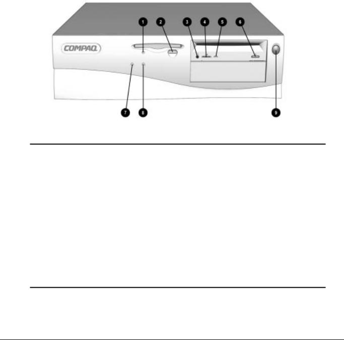
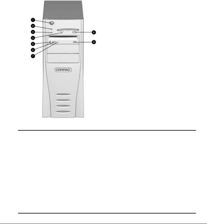
1.4.1Front Panel Controls and LEDs
The operator controls and LEDs located on the front panel of the computer are identified and described below.
Figure 1-2. Power Switch and Front Panel Lights
|
|
Table 1-3 |
|
|
Lights and Controls |
Ref. Component |
Function |
|
|
|
|
1 |
Diskette Drive Activity Light |
Turns on when the diskette drive is reading or writing. |
|
|
|
2 |
Diskette Eject Button |
Ejects a loaded diskette. |
|
|
|
3 |
CD-ROM Headphone Jack* |
Connects a headphone to the CD-ROM drive. |
|
|
|
4 |
CD-ROM Headphone Volume Control* |
Increases and decreases the CD-ROM headphone volume. |
|
|
|
5 |
CD-ROM Drive Activity Light* |
Turns on when the CD-ROM drive is reading information from the compact disc. |
|
|
|
6 |
CD-ROM Eject Button* |
Ejects a loaded disc. |
|
|
|
7 |
Power-On Light |
Turns on when the computer is turned on. |
|
|
|
8 |
Hard Drive Activity Light |
Turns on when the hard drive is reading or writing. |
|
|
|
9 |
Power Switch |
Turns the computer on and off. |
|
|
|
* Only available on models with CD-ROM.
1-14 Product Description
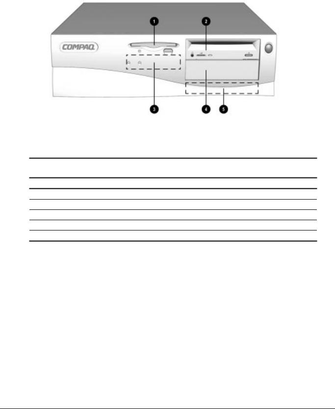
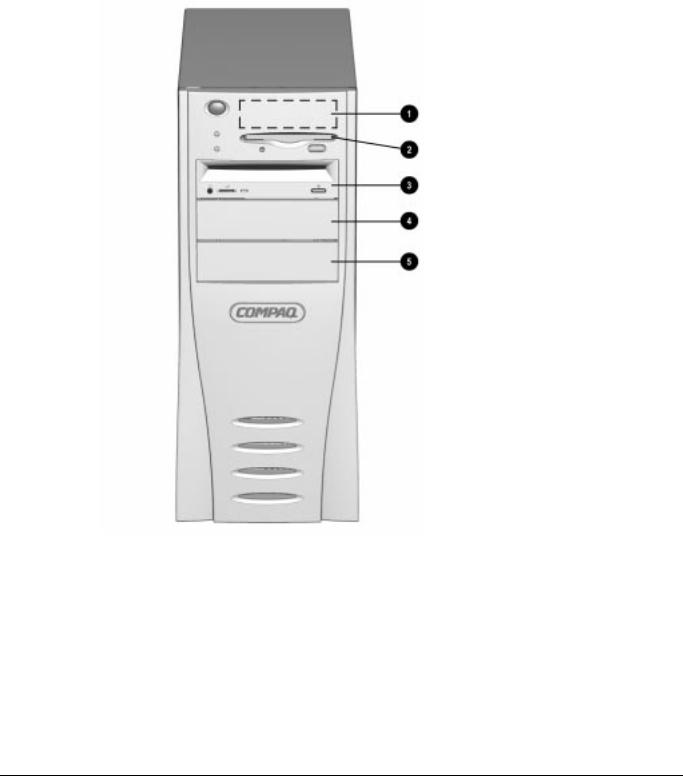
1.4.2Drive Positions
Figure 1-3. Drive Positions on the Compaq Deskpro 2000 Desktop Computer
The computer has space available for up to five mass storage devices. They may be installed in various configurations, including those shown in the following table.
Table 1-4
Compaq Deskpro 2000 Desktop Computer
Drive Configuration
1Standard 3.5-inch 1.44-MB diskette drive
2Optional diskette drive (5.25-inch), tape drive, hard drive, LS-120 drive, or CD-ROM drive (half-height)
3Primary hard drive bay (3.5-inch, third-height)
4Optional diskette drive (5.25-inch), tape drive, hard drive, LS-120 drive, or CD-ROM drive (half-height)
5Optional hard drive bay (5.25-inch, third-height)
To verify the type, size, and capacity of the mass storage devices installed in the computer, run the View System Information (INSPECT) utility available at computer startup. Refer to Chapter 2, "Compaq Utilities," for more information.
Compaq Deskpro 2000 Series of Personal Computers |
1-15 |
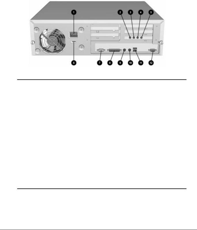
1.4.3Rear Panel Connectors
Rear panel connectors on your desktop computer are color-coded and include icons to help you identify their functions.
Figure 1-4. Rear Panel Connectors
|
|
Table 1-5 |
|
|
Rear Panel Connectors |
Ref. |
Component |
Function |
|
|
|
1 |
Power Cord Connector |
Connects the computer to an electrical power outlet. |
|
|
|
2 |
Microphone Connector* |
Connects a microphone for recording sound and voice. |
|
|
|
3 |
Line-In Audio Connector* |
Connects an external audio input device. |
|
|
|
4 |
Line-Out Audio Connector* |
Connects an external audio output device, such as powered speakers, or a cassette tape |
|
|
recorder. |
|
|
|
5 |
Headphone Connector* |
Connects headphones (not suitable for unpowered speakers). |
|
|
|
6 |
Voltage Select Switch |
Switches voltage between 115 V (U.S.) and 230 V to match geographical requirements. |
|
|
|
7 |
Serial Connector |
Connects a serial device, such as a serial printer. |
|
|
|
8 |
Parallel Connector |
Connects a parallel device, such as a parallel printer. |
|
|
|
9 |
Keyboard Connector |
Connects the keyboard. |
|
|
|
: |
Mouse Connector |
Connects the mouse. |
|
|
|
q |
Universal Serial Bus |
Connects the computer to any peripheral while the computer is operating. Is a fully |
|
Connector |
functional Plug and Play connector. |
|
|
|
< |
Monitor Connector |
Connects a monitor to an embedded graphics controller. |
|
|
|
* Audio features are available on select models only.
1-16 Product Description
1.5 Minitower Computer Features
The Compaq Deskpro 2000 Minitower Personal Computer comes with a mouse and keyboard. Not supplied is a Compaq color monitor or other compatible monitor, which is required to operate your computer.
1.5.1Front Panel Lights and Controls
Figure 1-5. Power Switch and Front Panel Lights
|
|
Table 1-6 |
|
|
Lights and Controls |
Ref. |
Component |
Function |
|
|
|
1 |
Power Switch |
Turns the computer on and off. |
|
|
|
2 |
Power-On Light |
Turns on when the computer is turned on. |
|
|
|
3 |
Hard Drive Activity Light |
Turns on when the hard drive is reading or writing. |
|
|
|
4 |
Diskette Drive Activity Light |
Turns on when the diskette drive is reading or writing. |
|
|
|
5 |
CD-ROM Headphone Jack* |
Connects a headphone to the CD-ROM drive. |
|
|
|
6 |
CD-ROM Headphone Volume Control* |
Increases and decreases the CD-ROM headphone volume. |
|
|
|
7 |
CD-ROM Drive Activity Light* |
Turns on when the CD-ROM drive is reading. |
|
|
|
8 |
Diskette Eject Button |
Ejects a diskette. |
|
|
|
9 |
CD-ROM Eject Button* |
Ejects a CD disc. |
|
|
|
* Only available on models with CD-ROM.
Compaq Deskpro 2000 Series of Personal Computers |
1-17 |
1.5.2Drive Positions
The computer has space available up to five mass storage devices. The devices may be installed in various configurations, including those shown in the table below.
Figure 1-6. Drive Positions on the Minitower Computer
1-18 Product Description
Loading...