


 Loading...
Compaq Armada M300
Series of Personal Computers
Maintenance and Service Guide

DOCUMENTATION SURVEY
Does the Maintenance and Service Guide contain all needed information? ο Yes ο No
If not, what additional information would you like to see in the guide?
Is the guide easy to use? ο Yes |
ο No |
If not, please explain: |
|
|
|
|
|
|
|
Is the artwork easy to interpret? |
ο Yes |
ο No If not, please explain: |
|
|
What information in the guide do you use most frequently?
What information do you use least?
How often do you refer to the Maintenance and Service Guide?
In what form would you prefer to receive information? (Rank 1 to 5, with 1 representing the most preferred.)
Maintenance and Service Guide on CD-ROM
Maintenance and Service Guide on Compaq Web site
Maintenance and Service Guide on QuickFind
Printed Maintenance and Service Guide
A combination of the above (please specify)
How do you receive Maintenance and Service Guides?
Is the guide available in a timely manner (when you need it)? |
ο Yes ο No |
If not, please explain: |
|||||||
|
|
|
|
|
|
|
|
|
|
|
|
|
|
|
|
|
|
|
|
Are sufficient quantities of the Maintenance and Service Guide available? ο Yes |
ο No |
If not, please explain: |
|||||||
|
|
|
|
|
|
|
|
|
|
|
|
|
|
|
|
|
|
|
|
Additional Documentation Comments: |
|
|
|
|
|
|
|
|
|
|
|
|
|
|
|
|
|
|
|
|
|
|
|
|
|
|
|
|
|
Name: |
|
|
|
|
|
Phone: |
|
|
|
Job Title: |
|
|
|
|
|
Company: |
|
|
|
Address: |
|
|
|
|
|
|
|
|
|
City: |
|
|
State: |
|
|
|
|
Zip: |
|
Armada M300 Series of Personal Computers
Notice
2000 Compaq Computer Corporation.
COMPAQ, the Compaq logo, and ARMADA Registered in U. S. Patent and Trademark Office
Microsoft, Windows, Windows NT, are registered trademarks of Microsoft Corporation in the United States and/or other countries. Intel and Pentium are registered trademarks of Intel Corporation in the United States and other countries.
All other product names mentioned herein may be trademarks or registered trademarks of their respective companies.
Compaq shall not be liable for technical or editorial errors or omissions contained herein. The information in this document is subject to change without notice and is provided “as is” without warranty of any kind. The entire risk arising out of the use of this information remains with the recipient. In no event shall Compaq be liable for any direct, consequential, incidental, special, punitive, or other damages whatsoever (including without limitation, damages for loss of business profits, business interruption, or loss of business information), even if Compaq has been advised of the possibility of such damages. The limited warranties for Compaq products are exclusively set forth in the documentation accompanying such products. Nothing herein should be construed as constituting a further or additional warranty.
MAINTENANCE AND SERVICE GUIDE
Compaq Armada M300 Series of Personal Computers
Second Edition February 2000
First Edition July 1999
Published in the U.S.A., U.K., Singapore, and Taiwan.
Documentation Part Number 113732-002
Spare Part Number 158339-001

CONTENTS
preface
USING THIS GUIDE ........................................................................................................................................... |
VII |
|
chapter 1 |
|
|
PRODUCT DESCRIPTION |
|
|
1.1 |
Computer Features and Models...................................................................................................... |
1-1 |
|
Models ........................................................................................................................................... |
1-2 |
|
Features ......................................................................................................................................... |
1-4 |
|
Intelligent Manageability .............................................................................................................. |
1-5 |
|
Accessing the Web Agent ............................................................................................................. |
1-5 |
|
Asset Management ........................................................................................................................ |
1-5 |
|
Fault Management......................................................................................................................... |
1-6 |
|
Fault Management Alerts.............................................................................................................. |
1-6 |
|
Security Management ................................................................................................................... |
1-6 |
|
Configuration Management .......................................................................................................... |
1-7 |
|
Managing Power ........................................................................................................................... |
1-7 |
|
Accessing Power Management ..................................................................................................... |
1-7 |
|
Power Management Levels........................................................................................................... |
1-7 |
1.2 |
Computer External Components .................................................................................................... |
1-8 |
1.3 |
Design Overview......................................................................................................................... |
1-15 |
|
System Board .............................................................................................................................. |
1-15 |
chapter 2 |
|
|
TROUBLESHOOTING |
|
|
2.1 |
Preliminary Steps ............................................................................................................................ |
2-2 |
2.2 |
Clearing Passwords......................................................................................................................... |
2-3 |
2.3 |
Power-On Self-Test (POST)........................................................................................................... |
2-3 |
2.4 |
POST Error Messages..................................................................................................................... |
2-4 |
2.5 |
Compaq Utilities ............................................................................................................................. |
2-6 |
2.6 |
Troubleshooting Without Diagnostics .......................................................................................... |
2-12 |
|
Before Replacing Parts................................................................................................................ |
2-12 |
|
Obtaining Update Information with Info messenger.................................................................. |
2-12 |
|
Checklist for Solving Problems .................................................................................................. |
2-13 |
chapter 3 |
|
|
ILLUSTRATED PARTS CATALOG |
|
|
3.1 |
Serial Number Location.................................................................................................................. |
3-1 |
3.2 |
Computer Major System Components ........................................................................................... |
3-2 |
3.3 |
Miscellaneous Plastic Kit Components.......................................................................................... |
3-4 |
3.4 |
Mass Storage Devices..................................................................................................................... |
3-5 |
3.5 |
Miscellaneous.................................................................................................................................. |
3-6 |
ContentsArmada M300 Maintenance and Service Guide iii

chapter 4
REMOVAL AND REPLACEMENT PRELIMINARIES
4.1 |
|
Tools Required................................................................................................................................ |
1-1 |
4.2 |
Service Considerations.................................................................................................................... |
1-1 |
|
|
|
Plastic Parts ................................................................................................................................... |
4-1 |
|
|
Cables and Connectors.................................................................................................................. |
4-2 |
4.3 |
Preventing Damage to Removable Drives ..................................................................................... |
1-2 |
|
4.4 |
Preventing Electrostatic Damage .................................................................................................... |
1-3 |
|
|
|
Packaging and Transporting Precautions...................................................................................... |
4-3 |
|
|
Workstation Precautions ............................................................................................................... |
4-4 |
|
|
Grounding Equipmemt amd Methods .......................................................................................... |
4-5 |
|
|
Electrostatic Voltage Levels and Protective Matherials............................................................... |
4-6 |
chapter 5 |
|
||
REMOVAL AND REPLACEMENT PROCEDURES |
|
||
5.1 |
Serial Number ................................................................................................................................. |
5-1 |
|
5.2 |
|
Disassembly Reference Chart......................................................................................................... |
5-2 |
5.3 |
Disconnecting the Computer from the Mobile Expansion Unit .................................................... |
5-3 |
|
5.4 |
|
Disconnecting the Computer .......................................................................................................... |
5-4 |
5.5 |
|
Preparing the Computer for Disassembly ...................................................................................... |
5-5 |
5.6 |
|
Battery Packs................................................................................................................................... |
5-6 |
|
|
Removing the Battery Pack........................................................................................................... |
5-6 |
|
|
Replacing the Battery Pack ........................................................................................................... |
5-7 |
5.7 |
Hard Drives ..................................................................................................................................... |
5-8 |
|
|
|
Removing a Hard Drive ................................................................................................................ |
5-8 |
|
|
Inserting a Hard Drive................................................................................................................... |
5-9 |
5.8 |
PC Cards ........................................................................................................................................ |
5-10 |
|
|
|
Removing a PC Card................................................................................................................... |
5-11 |
|
|
Inserting a PC Card ..................................................................................................................... |
5-12 |
5.9 |
Modem or Modem/NIC Card ....................................................................................................... |
5-13 |
|
5.10 |
Real Time Clock (RTC) Battery................................................................................................. |
5-15 |
|
5.11 |
Keyboard ..................................................................................................................................... |
5-16 |
|
5.12 Memory Expansion...................................................................................................................... |
5-18 |
||
|
|
Removing the Memory Expansion Board .................................................................................. |
5-18 |
|
|
Installing the Memory Expansion Board.................................................................................... |
5-19 |
5.13 |
Switch Cover............................................................................................................................... |
5-20 |
|
5.14 |
Display Assembly ....................................................................................................................... |
5-22 |
|
5.15 |
Top Cover with TouchPad.......................................................................................................... |
5-23 |
|
5.16 |
Voltage Converter Board ............................................................................................................ |
5-25 |
|
5.17 |
Modem Connector Board............................................................................................................ |
5-26 |
|
5.18 |
PC Card Assembly...................................................................................................................... |
5-28 |
|
5.19 |
System Board .............................................................................................................................. |
5-29 |
|
iv ContentsArmada M300 Maintenance and Service Guide

chapter 6
SPECIFICATIONS
6.1 |
Physical and Environmental |
...........................................................................................................6-1 |
6.2 |
Display ............................................................................................................................................ |
6-2 |
6.3 |
Hard Drive....................................................................................................................................... |
6-3 |
6.4 |
Diskette Drive ................................................................................................................................. |
6-4 |
6.5 |
Li-Ion Battery Pack......................................................................................................................... |
6-4 |
6.6 |
CD-ROM Drive .............................................................................................................................. |
6-5 |
6.7 |
DVD-ROM Drive ........................................................................................................................... |
6-6 |
6.8 |
System Interrupts ............................................................................................................................ |
6-7 |
6.9 |
System DMA................................................................................................................................... |
6-7 |
6.10 System I/O Addresses................................................................................................................... |
6-8 |
|
6.11 System Memory Map.................................................................................................................... |
6-9 |
|
appendix A |
|
|
CONNECTOR PIN ASSIGNMENTS ...................................................................................................................... |
A-1 |
|
appendix B |
|
|
POWER CORD SET REQUIREMENTS .................................................................................................................. |
B-1 |
|
INDEX |
........................................................................................................................................................... |
I-1 |
ContentsArmada M300 Maintenance and Service Guide v

preface
USING THIS GUIDE
This Maintenance and Service Guide is a troubleshooting reference that can be used when servicing the Compaq Armada M300 Series of Personal Computers.
Compaq Computer Corporation reserves the right to make changes to the Compaq Armada M300 Series of Personal Computers without notice.
Symbols
The following words and symbols mark special messages throughout this guide:
WARNING: Text set off in this manner indicates that failure to follow directions in the warning could result in bodily harm or loss of life.
CAUTION: Text set off in this manner indicates that failure to follow directions in the caution could result in damage to equipment or loss of information.
IMPORTANT: Text set off in this manner presents clarifying information or specific instructions.
NOTE: Text set off in this manner presents commentary, sidelights, or interesting points of information.
Technician Notes
WARNING: Only authorized technicians trained by Compaq should repair this equipment. All troubleshooting and repair procedures are detailed to allow only subassembly/module level repair. Because of the complexity of the individual boards and subassemblies, no one should attempt to make repairs at the component level or to make modifications to any printed wiring board. Improper repairs can create a safety hazard. Any indication of component replacement or printed wiring board modifications may void any warranty or exchange allowances.
WARNING: The computer is designed to be electrically grounded. To ensure proper operation, plug the AC power cord into a properly grounded electrical outlet only.
CAUTION: To properly ventilate the system, you must provide at least 3 inches (7.62 cm) of clearance on the left and right sides of the computer.
Preface vii

Serial Number
When requesting information or ordering spare parts, provide the computer serial number. The serial number is on the bottom of the computer.
Locating Additional Information
In addition to this guide, the following documentation provides information for the computer:
■Compaq Armada M300 Series of Personal Computers documentation set
■Microsoft Operating System Manual
■Compaq Service Training Guides
■Compaq Service Advisories and Bulletins
■Compaq QuickFind
■Compaq Service Quick Reference Guide
■Compaq Internet site at http://www.Compaq.com
Viii Preface
chapter 1
PRODUCT DESCRIPTION
1.1 Computer Features and Models
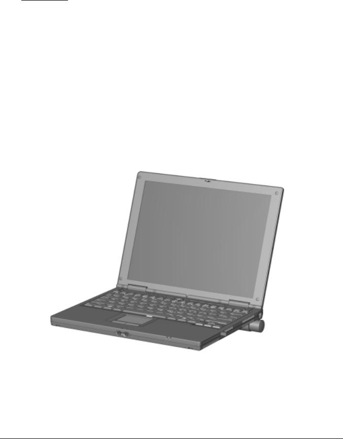
The Compaq Armada M300 Series of Personal Computers is an ultralight 3.1 to
3.3 pound (1.4 to 1.5 kg) computer (depending on configuration). It allows users high mobility, provides a full set of system ports, and when paired with the optional Mobile Expansion Unit (MEU), transforms into a full-function portable with enterprise docking capability.
Figure 1-1. Compaq Armada M300 Personal Computer
Product Description |
1-1 |

Models
The Armada M300 models are shown in Table 1-1. The computer model designation is composed of a group of characters that define each model’s features.
Table 1-1
Models and Model Naming Convention
Compaq Armada M300 Series of Personal Computers
Key
A |
|
|
M |
3 |
|
|
|
P3 |
|
|
500 |
|
|
|
T |
|
|
1 |
|
|
X |
|
12 |
|
|
|
0 |
M |
|
128 |
58 |
|
N |
|
S |
F |
||||
1 |
|
|
|
|
|
|
|
|
|
5-6 |
|
|
7-9 |
|
|
|
|
|
|
|
|
|
|
|
|
|
|
|
|
|
|
|
|
22 |
|
23 |
|
|||
|
|
2 |
|
3 |
|
4 |
|
|
|
|
|
|
10 |
|
11 |
|
12 |
13-14 |
|
15 |
16 |
|
17-19 |
20-21 |
|
|
24 |
|||||||||||||
Key |
|
|
Description |
|
|
|
Options |
|
|
|
|
|
|
|
|
|
|
|
|
|
|
|
|
|
|
|||||||||||||||
|
|
|
|
|
|
|
|
|
|
|
|
|
|
|
|
|
|
|
|
|
|
|
|
|
|
|
||||||||||||||
|
1 |
|
|
Brand designator |
|
|
|
A = Armada |
|
|
|
|
|
|
|
|
|
|
|
|
|
|
|
|
|
|
||||||||||||||
|
2 |
|
|
Segment designator |
M = Mobility |
|
|
|
|
|
|
|
|
|
|
|
|
|
|
|
|
|
|
|||||||||||||||||
|
3 |
|
|
Series |
|
|
|
|
|
|
3 = 300 |
|
|
|
|
|
|
|
|
|
|
|
|
|
|
|
|
|
|
|
|
|||||||||
|
4 |
|
|
Blank |
|
|
|
|
|
|
|
|
|
|
|
|
|
|
|
|
|
|
|
|
|
|
|
|
|
|
|
|
|
|
|
|||||
|
5-6 |
|
|
Processor type |
|
|
|
P3 = Intel Pentium III |
|
|
|
P2 = Intel Pentium II |
|
|
C = Intel Celeron |
|
||||||||||||||||||||||||
|
|
|
|
|
|
|
|
|
|
|
|
|
|
|
|
|
|
processor with 256 |
|
processor with 256 |
|
|
processor with 128 |
|||||||||||||||||
|
|
|
|
|
|
|
|
|
|
|
|
|
|
|
|
|
|
KB cache |
|
|
|
|
|
|
KB cache |
|
|
KB cache |
|
|
||||||||||
|
7-9 |
|
|
Processor speed |
|
|
|
500 = 500 MHz |
|
|
|
450 = 450 MHz |
|
|
333 = 333 MHz |
|
||||||||||||||||||||||||
|
10 |
|
|
Panel type |
|
|
|
T = TFT |
|
|
|
|
|
|
|
|
|
|
|
|
|
|
|
|
|
|
||||||||||||||
|
11 |
|
|
Panel size |
|
|
|
1 = 11.x” |
|
|
|
|
|
|
|
|
|
|
|
|
|
|
|
|
|
|
||||||||||||||
|
12 |
|
|
Panel resolution |
|
|
|
X = XGA |
|
|
|
|
|
S = SVGA |
|
|
|
|
|
|
|
|
|
|
||||||||||||||||
13-14 |
|
|
Hard drive size (in |
|
|
|
12 = 12.0 GB |
|
|
|
|
|
6 = 6.4 GB |
|
|
|
|
4 = 4.3 GB |
|
|
||||||||||||||||||||
|
|
|
|
|
|
|
GB, 1-2 digits) |
|
|
|
|
|
|
|
|
|
|
|
|
|
|
|
|
|
|
|
|
|
|
|
|
|
|
|
|
|||||
|
15 |
|
|
Optical drive |
|
|
|
0 = none |
|
|
|
|
|
|
|
|
|
|
|
|
|
|
|
|
|
|
||||||||||||||
|
16 |
|
|
Integrated |
|
|
|
|
|
|
M = Mini PCI V.90 |
|
|
|
C = NIC/modem |
|
|
0 = none |
|
|
||||||||||||||||||||
|
|
|
|
|
|
|
communication |
|
|
|
|
|
Modem |
|
|
|
|
|
|
combination |
|
|
|
|
|
|
|
|
||||||||||||
17-19 |
|
|
RAM (in MB, |
|
|
|
64 = 64 MB |
|
|
|
|
|
|
|
|
|
|
|
|
|
|
|
|
|
|
|||||||||||||||
|
|
|
|
|
|
|
2-3 digits) |
|
|
|
|
|
|
|
|
|
|
|
|
|
|
|
|
|
|
|
|
|
|
|
|
|
|
|
|
|||||
20-21 |
|
|
Operating system |
|
|
|
95 = Windows 95 |
|
|
|
|
|
|
N4 = Windows NT 4.0 |
|
|
||||||||||||||||||||||||
|
|
|
|
|
|
|
|
|
|
|
|
|
|
|
|
98 = Windows 98 |
|
|
|
|
|
|
N2 = Windows 2000 |
|
|
|
|
|||||||||||||
|
|
|
|
|
|
|
|
|
|
|
|
|
|
|
|
58 = Windows 95/98 dual install |
|
N4/N2 = Windows NT 4.0/2000 |
|
|||||||||||||||||||||
|
|
|
|
|
|
|
|
|
|
|
|
|
|
|
|
|
|
|
|
|
|
|
|
|
|
|
|
|
|
|
|
|
dual install |
|
|
|
|
|||
|
22 |
|
|
NAFTA |
|
|
|
|
|
|
N = NAFTA |
|
|
|
|
|
|
|
|
|
|
|
|
|
|
|
|
|
|
|||||||||||
|
23 |
|
|
Pointing device |
|
|
|
P = TouchPad |
|
|
|
|
|
|
|
|
|
|
|
|
|
|
|
|
||||||||||||||||
|
24 |
|
|
Security |
|
|
|
|
|
|
|
|
|
|
|
|
|
|
|
|
|
|
|
|
|
|
|
|
|
|
|
|
|
|
|
|||||
|
|
|
|
|
|
|
|
|
|
|
|
|
|
|
|
|
|
|
|
|
|
|
|
|
|
|
|
|
|
|
|
|
|
|
|
|
|
|
|
|
1-2 Product Description
Table 1-2
Models and Model Naming Convention
Compaq Armada M700 Series of Personal Computers
1 |
|
2 |
|
3 |
|
4 |
|
5-6 |
|
7-9 |
|
10 |
|
11 |
|
12 |
|
13-14 |
|
15 |
|
16 |
|
17-19 |
|
20-21 |
|
22 23 24 |
|
SKU# |
||||
A |
|
M |
|
3 |
|
|
|
P3 |
|
500 |
|
T |
|
1 |
|
X |
|
12 |
|
0 |
|
C |
|
128 |
|
58 |
|
|
|
P |
|
|
|
165288-XX2 |
A |
|
M |
3 |
|
|
|
P3 |
500 |
|
T |
1 |
|
X |
12 |
0 |
|
C |
128 |
|
N4/N2 |
|
|
|
P |
|
165288-XX6 |
||||||||
A |
|
M |
3 |
|
|
|
P3 |
500 |
|
T |
1 |
|
S |
12 |
0 |
0 |
64 |
58 |
|
|
|
P |
|
152547-XX2 |
||||||||||
A |
|
M |
3 |
|
|
|
P3 |
500 |
|
T |
1 |
|
S |
12 |
0 |
0 |
64 |
|
N4/N2 |
|
|
|
P |
|
152547-XX6 |
|||||||||
A |
|
M |
3 |
|
|
|
P3 |
500 |
|
T |
1 |
|
S |
12 |
0 |
|
M |
64 |
58 |
|
|
|
P |
|
152548-XX2 |
|||||||||
|
|
|
|
|
|
|
|
|
|
|
|
|
|
|
|
|
|
|
|
|
|
|
|
|
|
|
||||||||
A |
|
M |
3 |
|
|
|
P3 |
500 |
|
T |
1 |
|
S |
12 |
0 |
|
M |
64 |
|
N4/N2 |
|
|
|
P |
|
152548-XX6 |
||||||||
|
|
|
|
|
|
|
|
|
|
|
|
|
|
|
|
|
|
|
|
|
|
|
|
|
|
|||||||||
A |
|
M |
3 |
|
|
|
P3 |
500 |
|
T |
1 |
|
S |
12 |
0 |
|
C |
64 |
58 |
|
|
|
P |
|
152549-XX2 |
|||||||||
|
|
|
|
|
|
|
|
|
|
|
|
|
|
|
|
|
|
|
|
|
|
|
|
|
|
|
||||||||
A |
|
M |
3 |
|
|
|
P3 |
500 |
|
T |
1 |
|
S |
12 |
0 |
|
C |
64 |
|
N4/N2 |
|
|
|
P |
|
152549-XX6 |
||||||||
|
|
|
|
|
|
|
|
|
|
|
|
|
|
|
|
|
|
|
|
|
|
|
|
|
|
|
|
|
|
|
|
|
|
|
A |
|
M |
3 |
|
|
|
C |
450 |
|
T |
1 |
|
S |
6 |
0 |
0 |
64 |
58 |
|
|
|
P |
|
152544-XX2 |
||||||||||
|
|
|
|
|
|
|
|
|
|
|
|
|
|
|
|
|
|
|
|
|
|
|
|
|
|
|||||||||
A |
|
M |
3 |
|
|
|
C |
450 |
|
T |
1 |
|
S |
6 |
0 |
0 |
64 |
|
N4/N2 |
|
|
|
P |
|
152544-XX6 |
|||||||||
A |
|
M |
3 |
|
|
|
C |
450 |
|
T |
1 |
|
S |
6 |
0 |
|
M |
64 |
58 |
|
|
|
P |
|
152545-XX2 |
|||||||||
A |
|
M |
3 |
|
|
|
C |
450 |
|
T |
1 |
|
S |
6 |
0 |
|
M |
64 |
|
N4/N2 |
|
|
|
P |
|
152545-XX6 |
||||||||
A |
|
M |
3 |
|
|
|
C |
450 |
|
T |
1 |
|
S |
6 |
0 |
|
C |
64 |
58 |
|
|
|
P |
|
152546-XX2 |
|||||||||
A |
|
M |
|
3 |
|
|
|
C |
|
450 |
|
T |
|
1 |
|
S |
|
6 |
|
0 |
|
C |
|
64 |
|
N4/N2 |
|
|
|
P |
|
|
|
152546-XX6 |
A |
|
M |
3 |
|
|
|
P2 |
333 |
|
T |
1 |
|
S |
6 |
0 |
|
C |
64 |
95 |
|
|
|
P |
|
138594-XX2 |
|||||||||
A |
|
M |
3 |
|
|
|
P2 |
333 |
|
T |
1 |
|
S |
6 |
0 |
|
C |
64 |
98 |
|
|
|
P |
|
138594-XX4 |
|||||||||
|
|
|
|
|
|
|
|
|
|
|
|
|
|
|
|
|
|
|
|
|
|
|
|
|
|
|
||||||||
A |
|
M |
3 |
|
|
|
P2 |
333 |
|
T |
1 |
|
S |
6 |
0 |
|
C |
64 |
|
N4 |
|
|
|
P |
|
138594-XX6 |
||||||||
|
|
|
|
|
|
|
|
|
|
|
|
|
|
|
|
|
|
|
|
|
|
|
|
|
|
|
|
|
|
|
|
|
|
|
A |
|
M |
3 |
|
|
|
C |
333 |
|
T |
1 |
|
S |
4 |
0 |
|
C |
64 |
95 |
|
|
|
P |
|
138595-XX2 |
|||||||||
|
|
|
|
|
|
|
|
|
|
|
|
|
|
|
|
|
|
|
|
|
|
|
|
|
|
|||||||||
A |
|
M |
3 |
|
|
|
C |
333 |
|
T |
1 |
|
S |
4 |
0 |
|
C |
64 |
98 |
|
|
|
P |
|
138595-XX4 |
|||||||||
|
|
|
|
|
|
|
|
|
|
|
|
|
|
|
|
|
|
|
|
|
|
|
|
|
|
|
||||||||
A |
|
M |
3 |
|
|
|
C |
333 |
|
T |
1 |
|
S |
4 |
0 |
|
C |
64 |
|
N4 |
|
|
|
P |
|
138595-XX6 |
||||||||
|
|
|
|
|
|
|
|
|
|
|
|
|
|
|
|
|
|
|
|
|
|
|
|
|
|
|
|
|
|
|
|
|
|
|
A |
|
M |
3 |
|
|
|
P2 |
333 |
|
T |
1 |
|
S |
6 |
0 |
|
O |
64 |
95 |
|
|
|
P |
|
107008-XX2 |
|||||||||
A |
|
M |
3 |
|
|
|
P2 |
333 |
|
T |
1 |
|
S |
6 |
0 |
0 |
64 |
98 |
|
|
|
P |
|
107031-XX4 |
||||||||||
A |
|
M |
3 |
|
|
|
P2 |
333 |
|
T |
1 |
|
S |
6 |
0 |
0 |
64 |
|
N4 |
|
|
|
P |
|
107051-XX6 |
|||||||||
A |
|
M |
3 |
|
|
|
P2 |
333 |
|
T |
1 |
|
S |
6 |
0 |
|
M |
64 |
95 |
|
|
|
P |
|
107009-XX2 |
|||||||||
A |
|
M |
3 |
|
|
|
P2 |
333 |
|
T |
1 |
|
S |
6 |
0 |
|
M |
64 |
98 |
|
|
|
P |
|
107032-XX4 |
|||||||||
A |
|
M |
|
3 |
|
|
|
P2 |
|
333 |
|
T |
|
1 |
|
S |
|
6 |
|
0 |
|
M |
|
64 |
|
N4 |
|
|
|
P |
|
|
|
107052-XX6 |
A |
|
M |
3 |
|
|
|
C |
333 |
|
T |
1 |
|
S |
4 |
0 |
|
O |
64 |
95 |
|
|
|
P |
|
107061-XX2 |
|||||||||
|
|
|
|
|
|
|
|
|
|
|
|
|
|
|
|
|
|
|
|
|
|
|
|
|
||||||||||
A |
|
M |
3 |
|
|
|
C |
333 |
|
T |
1 |
|
S |
4 |
0 |
0 |
64 |
98 |
|
|
|
P |
|
107062-XX4 |
||||||||||
|
|
|
|
|
|
|
|
|
|
|
|
|
|
|
|
|
|
|
|
|
|
|
|
|
|
|||||||||
A |
|
M |
3 |
|
|
|
C |
333 |
|
T |
1 |
|
S |
4 |
0 |
0 |
64 |
|
N4 |
|
|
|
P |
|
107067-XX6 |
|||||||||
|
|
|
|
|
|
|
|
|
|
|
|
|
|
|
|
|
|
|
|
|
|
|
|
|
|
|||||||||
A |
|
M |
3 |
|
|
|
C |
333 |
|
T |
1 |
|
S |
4 |
0 |
|
M |
64 |
95 |
|
|
|
P |
|
124788-XX2 |
|||||||||
|
|
|
|
|
|
|
|
|
|
|
|
|
|
|
|
|
|
|
|
|
|
|
|
|
|
|||||||||
A |
|
M |
3 |
|
|
|
C |
333 |
|
T |
1 |
|
S |
4 |
0 |
|
M |
64 |
98 |
|
|
|
P |
|
124789-XX4 |
|||||||||
|
|
|
|
|
|
|
|
|
|
|
|
|
|
|
|
|
|
|
|
|
|
|
|
|
|
|
||||||||
A |
|
M |
3 |
|
|
|
C |
333 |
|
T |
1 |
|
S |
4 |
0 |
|
M |
64 |
|
N4 |
|
|
|
P |
|
124790-XX6 |
||||||||
|
|
|
|
|
|
|
|
|
|
|
|
|
|
|
|
|
|
|
|
|
|
|
|
|
|
|
|
|
|
|
|
|
|
|
Product Description |
1-3 |

Features
The computer has the following features:
■Intel Pentium III 500-MHz, Intel Pentium II 333-MHz, or Celeron 450or 333-MHz processor, with 256-KB integrated L2 cache (Pentium III or II) or 128-KB integrated L2 cache (Celeron), depending on computer model
■ATI RAGE LT Pro, 4-MB SGRAM (synchronous graphics)
■Standard 64-MB high-performance synchronous DRAM (SDRAM), expandable to 512 MB
■Dual preinstall of Microsoft Windows 95 and Windows 98 or Windows NT Workstation 4.0 and Windows NT 2000 preinstalled*
■11.3-inch XGA CTFT (1024 × 768) and 11.3-inch SVGA CTFT (800 × 600) displays with 16 million colors, depending on computer model
■Keyboard is 95 percent of full-size with TouchPad pointing device
■Full set of ports on system (serial, parallel, USB, Infrared, VGA)
■Mini PCI 56K V.90 modem, or optional Mini PCI V.90 plus 10/100 NIC combo card
■One Type II PC Card slot with support for both 32-bit CardBus and 16-bit PC Cards; zoomed video support
■External AC adapter with power cord
■Lithium ion (Li-ion) battery packs
■Standard: 4 cell, 26 Watt hours (externally attaches to computer)
■Optional: 6 cell, 40 Watt hours (externally attaches to computer)
■Optional: MultiBay (for mobile expansion unit)
■High-capacity SMART hard drives, 12.0-, 6.4-, and 4.3-GB, with DriveLock security and Prefailure Warranty, depending on computer model
■Ultraportable form factor, 0.89 inch (2.3 cm) thin with weight starting at 3.1 lb. (1.4 kg), depending on configuration
■Standard external diskette drive (attaches to system through the parallel port or fits into the mobile expansion unit diskette drive bay)
■Optional Mobile Expansion Unit (MEU) conveniently adds:
■Dedicated diskette drive bay
■Flexible MultiBay that accommodates: 24X MAX CD-ROM drive or DVD-ROM drive, SuperDisk LS-120 drive, weight saver, second Li-Ion battery or secondary 6.4-GB hard drive
■Additional ports: parallel, serial, audio in/out, VGA, USB, PS/2 (2), AC power in, CPU connector, docking connector
■Stereo speakers providing Compaq PremierSound 16-bit stereo sound
■Robust, common enterprise docking solution
*End user must make a one-time selection between Windows 95 and Windows 98. If end user desires rejected product(s) after selection is made, end user must acquire and pay for rejected product(s) separately.
1-4 Product Description

Intelligent Manageability
Intelligent Manageability consists of preinstalled software tools for the computer and Compaq servers that assist in tracking, troubleshooting, protecting, and maintaining the computer. It provides the following functions:
■Asset Management: provides detailed configuration and diagnostic information.
■Fault Management: prevents, predicts, and alerts of impending hardware problems.
■Security Management: protects unauthorized access to data and components.
■Configuration Management: optimizes the computer by providing the latest drivers, utilities, and software, which are available on CD-ROM and the Compaq Web site at www.compaq.com/support/portables.
NOTE: For further help with Intelligent Manageability, select Start Compaq Information Center Intelligent Manageability
Accessing the Web Agent
The computer may have a preinstalled Web Agent that allows computer configuration information to be viewed using Web technology. To access this feature, select Start Compaq Information Center Insight Web Management.
If the computer does not have a preinstalled Web Agent, it can be downloaded from the Compaq Web site at www.compaq.com.
Asset Management
Asset Management enables component information to be retrieved when on the road or connected to the network.
Asset Management also enables the network administrator to remotely retrieve information from any Compaq computer connected to the network. The information can be used to assist in tracking and maintaining the computer and its components. It provides the following information:
■Inventory information—The network administrator can retrieve information about the computer over the network by using Compaq Insight Manager or any PC management tool provided by Compaq Solution Partners. Asset control information retrieved from the computer includes:
■Manufacturer, model, and serial number of Compaq computers, monitors, hard drives, battery packs, memory boards, processor speeds, and operating systems
■Asset tag
■System board and ROM revision levels
■BIOS settings
■Diagnostic information—Diagnostics for Windows includes information on hard drives, ports, video, sound, and other components. This application also allows the user to run multi-threaded tests on hardware components. If problems are found, recommendations are provided.
All of the above information can be viewed, printed, or saved.
Product Description |
1-5 |

Fault Management
Fault Management features minimize downtime and data loss by monitoring system performance and generating the following alerts:
■Hard drive alert—provides 72-hour advance warning of impending hard drive problems and can automatically start optional backup software.
■System temperature alert—reports overheating. As the system temperature rises, this feature first adjusts fan speed and other cooling components, then displays an alert, then shuts down the system.
■Battery pack alert—reports charging problems and battery pack failure.
■Monitor alert—diagnoses and displays external monitor operational problems.
■Memory alert—reports memory board configuration changes when a memory board is removed, added, or reconfigured. It also provides the previous and current configurations for comparison.
The alerts work with or without network connection. If the computer is not connected to the network, the network administrator cannot receive alerts from the computer.
Fault Management Alerts
Alerts can be enabled, disabled, and tested, and software can be set to back up information whenever a hard drive alert occurs.
■While the computer is connected to a network, alerts pop up on the computer display and are simultaneously reported to the network console.
■System temperature alert—reports overheating. As the system temperature rises, this feature first adjusts fan speed and other cooling components, then displays an alert, then shuts down the system.
NOTE: A battery charging problem alert is reported only on the computer display.
■When the computer is not connected to a network, the user will receive a local alert.
■To set alerts, select the Intelligent Manageability icon in the system tray.
Security Management
Security Management features customize system security.
■Power-On and Setup Passwords—prevent unauthorized access to information and computer configuration.
■DriveLock—prevents unauthorized access to hard drives.
■Device disabling—prevents unauthorized data transfer through modems, serial ports, parallel ports, and infrared ports on the computer and an optional docking station.
■QuickLock/QuickBlank—locks the keyboard and clears the screen.
■Ownership Tag—displays ownership information during system restart.
1-6 Product Description

Configuration Management
Configuration Management optimizes software upgrade and customer support procedures. Compaq provides support software to optimize the performance of the computer. This support software is accessible through a monthly CD-ROM subscription. Support software can also be downloaded from the Compaq Web site at www.compaq.com/support/ portables.
Managing Power
The computer comes with a collection of power management features that allow battery operating time to be extended and power to be conserved. Use power management to monitor most computer components such as the hard drive, processor, and display.
Accessing Power Management
■In Windows 95, select Start Settings Control Panel Power to view or adjust settings in Power Properties.
■In Windows NT 4.0, select Compaq Power instead of Power
■In Windows 98, select Power Management.
Power Management Levels
To extend the life of batteries, use the Battery Conservation tab in Power Properties.
■If Windows 95 is running, select Start Settings Control Panel Power to access Power Properties.
■In Windows NT 4.0, select Compaq Power instead of Power.
■In Windows 98, select Power Management.
The level of battery conservation or the selection of preset power management levels can be customized.
Product Description |
1-7 |
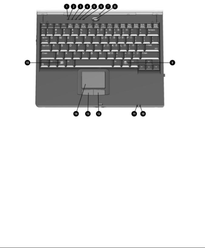
1.2 Computer External Components
The external components on the top of the computer are shown in Figure 1-2 and described in Table 1-2.
Figure 1-2. Top Components
1-8 Product Description

|
|
|
|
|
Table 1-3 |
|
|
|
Top Components |
||
|
|
|
|
|
|
Item |
Component |
|
Function |
||
|
|
|
|
|
|
1 |
|
Display switch |
|
|
Turns off the computer display if the computer is closed while |
|
|
|
|
|
on. |
|
|
|
|
|
|
2 |
|
Scroll lock light |
|
|
On: Scroll lock is on. |
|
|
|
|
|
|
3 |
|
Caps lock light |
|
|
On: Caps lock is on. |
4 |
|
Num lock light |
|
|
On: Num lock is on and the embedded numeric keypad is |
|
|
|
|
|
enabled. |
5 |
|
Hard drive light |
|
|
On: The primary hard drive is being accessed. |
|
|
|
|
|
|
6 |
|
Diskette drive light |
|
|
On: The external diskette drive is being accessed. |
|
|
|
|
|
|
7 |
|
Internal microphone |
|
|
Supports audio input when the display is open or closed. |
|
|
|
|
|
|
8 |
|
Suspend button |
|
|
Initiates and exits Suspend.* When pressed with the Fn key, |
|
|
|
|
|
initiates Hibernation. |
|
|
|
|
|
|
9 |
|
Windows application key |
|
|
Displays shortcut menu for item beneath mouse cursor. |
|
|
|
|
|
|
10 |
|
Battery light |
|
|
On: The battery pack is charging. |
|
|
|
|
|
Blinking: The battery pack, that is the only available power |
|
|
|
|
|
source, has reached a low-battery condition. |
|
|
|
|
|
|
11 |
|
Power/suspend light |
|
|
On: Power is turned on. |
|
|
|
|
|
Off: Power is turned off. |
|
|
|
|
|
Blinking: Computer is in Suspend.* |
|
|
|
|
|
NOTE: The power/suspend light also blinks if a battery pack that |
|
|
|
|
|
is the only source of power available to the computer reaches a |
|
|
|
|
|
critical low-battery condition while Hibernation is disabled. |
|
|
|
|
|
|
12 |
|
Right mouse button |
|
|
Functions like the right click button of an external mouse. |
|
|
|
|
|
|
13 |
|
Left mouse button |
|
|
Functions like the left-click button of an external mouse. |
|
|
|
|
|
Used with the TouchPad to drag and highlight. |
14 |
|
TouchPad |
|
|
Moves the mouse cursor, selects, and activates. |
|
|
|
|
|
|
15 |
|
Microsoft logo key |
|
|
Displays Windows Start menu. |
|
|
|
|
|
|
*In Windows 98 the term Standby replaces the term Suspend.
In Windows 98 the term sleep button replaces the term suspend button.
Product Description |
1-9 |
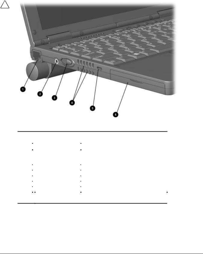
The external components on the left side of the computer are shown in Figure 1-3 and are described in Table 1-3.
Figure 1-3. Left Side Components
|
|
|
|
|
|
|
Table 1-4 |
|
|
|
|
|
Left Side Components |
||
|
|
|
|
|
|
|
|
Item |
Component |
|
Function |
||||
|
|
|
|
|
|
|
|
1 |
|
RJ-45 jack* |
|
|
Connects the network cable. |
||
|
|
|
|
|
|
|
NOTE: A network cable is included with network models. |
|
|
|
|
|
|
|
Internal modem/NIC models only |
|
|
|
|
|
|
|
|
2 |
|
Power connector |
|
|
Connects the AC power adapter. |
||
3 |
|
Power button |
|
|
Turns the computer on or off or exits Suspend. |
||
|
|
|
|
|
|
|
|
4 |
|
Vents |
|
|
Cools internal components. |
||
|
|
|
|
|
|
|
|
5 |
|
Security cable slot |
|
|
Attaches an optional security cable to the computer. |
||
|
|
|
|
|
|
|
|
6 |
|
Hard drive bay |
|
|
Holds primary hard drive. |
||
|
|
|
|
|
|
|
|
WARNING: To reduce the risk of electric shock, fire, or damage to the equipment, do not plug a telephone cable into the Ethernet RJ-45 jack.
1-10 Product Description
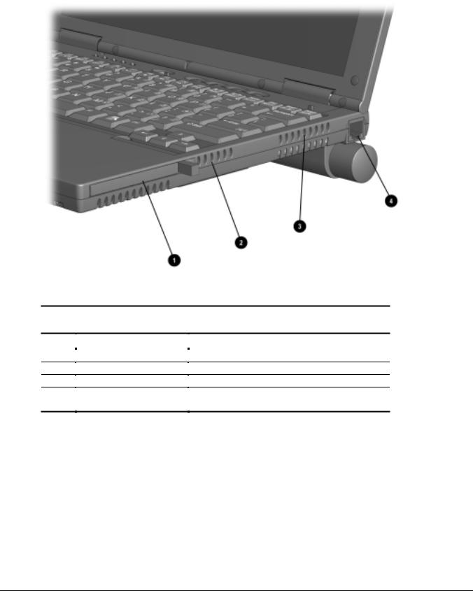
The external components on the right side of the computer are shown in Figure 1-4 and are described in Table 1-4.
Figure 1-4. Right Side Components
Table 1-5
Right Side Components
Item |
Component |
Function |
||
|
|
|
|
|
1PC Card slot
2Air intake vents
3Air exhaust vents
4RJ-11 jack (internal modem models only)
Supports 32-bit (CardBus) and 16-bit PC Cards.
Cool internal components.
Cool internal components.
Connects the modem cable to an internal modem.
NOTE: A modem cable is included with internal modem models.
Product Description |
1-11 |
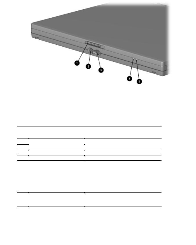
The external components of the front of the computer are shown in Figure 1-5 and described in Table 1-5.
Figure 1-5. Front Components
Table 1-6
Front Components
Component |
Function |
||
|
|
|
|
1Display release latch
2Stereo speaker/headphone jack
3Microphone jack
4Power/suspend light
5 Battery light
Opens the computer.
Connects stereo speakers, headphones, or headset audio.
Connects a single sound channel microphone.
On: Power is turned on. Off: Power is turned off.
Blinking: Computer is in Suspend.
NOTE: The power/suspend light also blinks if a battery pack that is the only source of power available to the computer reaches a critical low-battery condition while Hibernation is disabled.
On: A battery pack is charging.
Blinking: A battery pack that is the only available power source has reached a low-battery condition.
1-12 Product Description
The external components on the rear of the computer are shown in Figure 1-6 and described in Table 1-6.
Figure 1-6. Rear Components
|
|
|
|
|
Table 1-7 |
|
|
|
Rear Components |
||
|
|
|
|
|
|
Item |
Component |
|
Function |
||
|
|
|
|
|
|
1 |
|
USB connector |
|
|
Connects USB devices |
|
|
|
|
|
|
2 |
|
Serial connector |
|
|
Connects a serial device |
|
|
|
|
|
|
3 |
|
Parallel connector |
|
|
Connects a parallel device |
|
|
|
|
|
|
4 |
|
External monitor connector |
|
|
Connects an external monitor, overhead projector, or TV |
|
|
|
|
|
adapter. |
|
|
|
|
|
|
5 |
|
Infrared port |
|
|
Links to another IrDA-compliant device for wireless |
|
|
|
|
|
communication. |
|
|
|
|
|
|
6 |
|
Battery pack |
|
|
Provides power to the computer. |
|
|
|
|
|
|
Product Description |
1-13 |
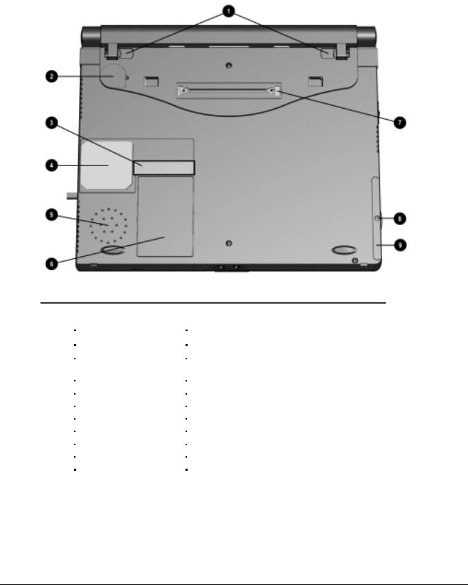
The external components on the bottom of the computer are shown in Figure 1-7 and are described in Table 1-7
Figure 1-7. Bottom Components
|
|
|
|
|
Table 1-8 |
|
|
|
Bottom Components |
||
|
|
|
|
|
|
Item |
Component |
|
Function |
||
|
|
|
|
|
|
1 |
|
Battery latches |
|
|
Release the primary battery pack. |
2 |
|
Real-time clock battery |
|
|
Provides battery power to automatically display the date and |
|
|
|
|
|
time. |
3 |
|
Serial number |
|
|
Numerical identification for the computer. |
|
|
|
|
|
|
4 |
|
Fan |
|
|
Cools the computer. |
|
|
|
|
|
|
5 |
|
Speaker |
|
|
Produces sound. |
|
|
|
|
|
|
6 |
|
Modem compartment |
|
|
Provides access to the internal modem (modem models only). |
7 |
|
docking connector |
|
|
Connects the computer to a docking base. |
|
|
|
|
|
|
8 |
|
Hard drive security screw |
|
|
Secures hard drive in computer hard drive bay. |
|
|
|
|
|
|
9 |
|
Hard drive bezel |
|
|
Releases a hard drive from the hard drive bay. |
|
|
|
|
|
|
1-14 Product Description

1.3 Design Overview
This section presents a design overview of key parts and features of the computer. Refer to Chapter 3 for the illustrated parts catalog and Chapter 5 for removal and replacement procedures.
System Board
The system board provides the following device connections:
■Memory expansion board
■Hard drive
■Display
■Keyboard/Touchpad pointing device
■Audio
■Pentium II/Celeron processor
■Fan
■PC Cards
■Modem
The computer is equipped with an Intel Pentium III 500-MHz, Intel Pentium II 333-MHz, or Celeron 450or 333-MHz processor. For ventilation, an electrical fan is installed. The fan is controlled by a temperature sensor. The fan is designed to turn on automatically when high temperature conditions exist. These conditions are affected by high external temperatures, system power consumption, power management/battery conservation configurations, battery fast charging, and software applications. Exhaust air is displaced through the ventilation grill located on the right side of the computer.
CAUTION: To properly ventilate the computer, allow at least a 3-inch (7.6 cm) clearance on the left and right sides of the computer.
Product Description |
1-15 |

chapter 2
TROUBLESHOOTING
Follow these basic steps when beginning the troubleshooting process:
1.Complete the preliminary steps listed in Section 2.1.
2.Run the Power-On Self-Test (POST) as described in Section 2.3.
3.Run Computer Setup as described in Section 2.5.
4.If you are unable to run POST or if the problem persists after running POST, perform the recommended actions described in the diagnostic tables in Section 2.5.
Follow these guidelines when troubleshooting:
■Complete the recommended actions in the order in which they are given.
■Repeat POST after each recommended action until the problem is resolved and the error message does not return.
■When the problem is resolved, stop performing the troubleshooting steps and do not complete the remaining recommended actions.
■Refer to Chapter 5 for recommended removal and replacement procedures.
■If the problem is intermittent, check the computer several times to verify that the problem is solved.
The following table describes the troubleshooting actions:
If You Want To: |
Then Run: |
|
|
Check for POST error messages |
POST |
|
|
Perform any of the following: |
Computer Setup |
■Check the system configuration
■Set the system power management parameters
■Return the system to its original configuration
■Check system configuration of installed devices
Troubleshooting 2-1

2.1 Preliminary Steps
IMPORTANT: Use AC power when running POST or Computer Setup. A low battery condition could initiate Hibernation and interrupt the test.
Before running POST, complete the following steps:
1.Obtain established passwords. If you must clear the passwords, go to Section 2.2.
2.Ensure that the battery pack is installed and the power cord is connected to the computer and plugged into an AC power source.
3.Turn on the computer.
4.If a power-on password has been established, type the password and press Enter.
5.Run Computer Setup (Section 2.5). If a Setup password has been established, type the password and press Enter.
6.Turn off the computer and all external devices.
7.Disconnect external devices that you do not want to test. If you want to use the printer to log error messages, leave it connected to the computer.
NOTE: If a problem only occurs when an external device is connected to the computer, the problem could be with the external device or its cable. Isolate the problem by running POST with and without the external device connected.
8.Use Compaq Utilities and loopback plugs in the serial and parallel connectors if you plan to test these ports.
Follow these steps to run Compaq Utilities:
a.If you are running Compaq Utilities from the hard drive, turn on or restart the computer. Press F10 when the cursor appears in the upper-right corner of the screen. If you do not press F10 in time, restart the computer and try again.
If you are running Compaq Utilities from diskette, insert the Compaq Utilities diskette in drive A. Turn on or restart the computer.
b.Press Enter to accept OK.
c.Select Prompted Diagnostics.
d.After “Identifying System Hardware” completes, select Interactive Testing and follow the instructions on the screen.
2-2 Troubleshooting

2.2Clearing Passwords
1.Turn off the computer.
2.Disconnect the computer (Section 5.4).
3.Remove the battery pack (Section 5.6).
4.Disconnect and remove the Real Time Clock (RTC) battery (Section 5.10).
5.Wait five minutes.
6.Reconnect the RTC battery.
7.Reconnect the AC Adapter. Do not reinstall the battery pack yet.
8.Turn on the computer.
NOTE: Remember to set the date and time the next time the computer is turned on.
2.3 Power-On Self-Test (POST)
The Power-On Self-Test (POST) is a series of tests that run every time the computer is turned on. POST verifies that the system is configured and functioning properly.
To run POST, complete the following steps:
1.Complete the preliminary steps (Section 2.1).
2.Turn on the computer.
If POST does not detect any errors, the computer beeps once or twice to indicate that POST has run successfully. The computer boots from the hard drive or from a bootable diskette if one is installed in the diskette drive.
Troubleshooting 2-3

2.4 POST Error Messages
If the system is not functioning well enough to run POST, or if the display is not functioning well enough to show POST error messages, refer to the Troubleshooting tables in Section 2.6.
If POST detects an error, one of the following events occurs:
■A message with the prefix "WARNING" appears, informing you where the error occurred. The system pauses until you press F1 to continue.
■A message with the prefix "FATAL" appears, informing you where the error occurred. After the message, the system emits a series of beeps, then stops.
■The system emits a series of beeps, then stops.
Warning messages indicate that a potential problem, such as a system configuration error, exists. When F1 is pressed, the system should resume. You should be able to correct problems that produce WARNING messages.
If you receive one of the error messages listed below, follow the recommended action.
Table 2-1
Warning Messages
Message |
Description |
Recommended Action |
|
|
|
CMOS checksum invalid, run SCU |
CMOS RAM information has |
Run Computer Setup to reinitialize |
|
been corrupted. |
CMOS-RAM. |
CMOS failure, run SCU |
CMOS RAM has lost power. |
Run Computer Setup to reinitialize CMOS-RAM.
Diskette controller error |
The diskette drive controller |
If there is no diskette drive in the |
|
|
failed to respond to the |
system, run Computer Setup to |
|
|
recalibrate command. |
properly configure the CMOS-RAM to |
|
|
|
show no diskette drive present. If the |
|
|
|
problem persists, or if a diskette drive |
|
|
|
is present, complete these steps until |
|
|
|
the problems is solved: |
|
|
|
1. |
Check diskette drive connections. |
|
|
2. |
Replace diskette drive. |
|
|
3. |
Replace system board. |
|
|
|
|
Diskette track 0 failed |
The diskette drive cannot read |
Try another diskette. If the problem |
|
|
track 0 of the diskette in the |
persists, you may need to replace the |
|
|
drive. |
diskette drive. |
|
Continued
2-4 Troubleshooting

Table 2-1 Continued
Message Description Recommended Action
Hard disk controller error |
The hard drive controller failed |
|
to respond to the reset |
|
command. |
Check the drive parameters. Turn off the system and check all related connections.
Keyboard controller failure |
The keyboard failed the self- |
Replace the system board. |
|
|
test command. |
|
|
|
|
|
|
Keyboard failure |
The keyboard failed to respond |
Replace the keyboard. If the problem |
|
|
to the RESET ID command. |
persists, replace the system board. |
|
|
|
|
|
No interrupts from Timer 0 |
The periodic timer interrupt is |
Replace the system board. |
|
|
not occurring. |
|
|
|
|
|
|
ROM at xxxx (LENGTH yyyy) with |
An illegal adapter ROM was |
Check the external adapter (such as a |
|
nonzero checksum (zz) |
located at the specified |
video card) to determine if it is |
|
|
address. |
causing the conflict. |
|
|
|
|
|
Time/Date corrupt - run SCU |
The time and date stored in |
1. Run Computer Setup. |
|
|
the real time clock have been |
2. If problems persists, replace |
|
|
corrupted, possibly by a power |
|
|
|
system board. |
|
|
|
loss. |
|
|
|
|
|
|
|
|
|
|
Hard disk xx failure (or error) |
A failure or an error occurred |
1. Run ScanDisk. |
|
|
when trying to access the hard |
2. Check disk in DOS and |
|
|
drive. |
|
|
|
Windows 95. |
|
|
|
|
|
Fatal errors emit a beep and may display a FATAL message. Fatal errors indicate severe problems, such as a hardware failure. Fatal errors do not allow the system to resume. Some of the Fatal error beep codes are listed at the end of this section.
Table 2-2
Fatal Error Messages
Message |
Description |
Beep code |
|
|
|
CMOS RAM test failed |
A walking bit test of CMOS RAM location 0E |
3 |
|
(Hex) - 3F (Hex) failed. |
|
|
|
|
DMA controller faulty |
A sequential read/write of the transfer count |
4 |
|
and transfer address registers within the |
|
|
primary and secondary DMA controllers failed. |
|
|
|
|
Faulty DMA page registers |
A walking bit read/write of the 16 DMA |
0 |
|
controller page registers starting at location 80 |
|
|
Hex failed. |
|
|
|
|
Faulty refresh circuits |
A continuous read/write test of port 61h found |
1 |
|
that bit 4 (Refresh Detect) failed to toggle |
|
|
within an allotted amount of time. |
|
|
|
|
Interrupt controller failed |
A sequential read/write of various Interrupt |
5 |
|
Controller registers failed. |
|
|
|
|
ROM checksum incorrect |
A checksum of the ROM BIOS does not match |
2 |
|
the byte value at F000:FFFF. |
|
|
|
|
RAM error at location xxxx |
RAM error occurred during memory test. |
None |
|
|
|
*Beep codes are defined in Table 2-3. |
|
|
|
|
|
Troubleshooting 2-5

Table 2-3
Fatal Error Beep Codes
Beep Code |
Beep Sequence |
Description |
Recommended Action |
|
|
|
|
0 |
S-S-S-P-S-S-L-P |
The DMA page registers are |
Replace system board. |
|
|
faulty. |
|
|
|
|
|
1 |
S-S-S-P-S-L-S-P |
The refresh circuitry is faulty. |
|
|
|
|
|
2 |
S-S-S-P-S-L-L-P |
The ROM checksum is incorrect. |
|
|
|
|
|
3 |
S-S-S-P-L-S-S-P |
The CMOS RAM test failed. |
|
|
|
|
|
4 |
S-S-S-P-L-S-L-P |
The DMA controller is faulty. |
|
|
|
|
|
5 |
S-S-S-P-L-L-S-P |
The interrupt controller failed. |
|
|
|
|
|
6 |
S-S-S-P-L-L-L-P |
The keyboard controller failed. |
|
|
|
|
|
7 |
S-S-L-P-S-S-S-P |
Graphics adapter is faulty. |
|
|
|
|
|
8 |
S-S-L-P-S-S-L-P |
Internal RAM is faulty. |
Replace memory board or |
|
|
|
system board if memory on |
|
|
|
system board is faulty. |
|
|
|
|
NOTE: S = Short, L = Long, P = Pause
2.5 Compaq Utilities
Compaq Utilities contain several functions that
■Determine if various computer devices are recognized by the system and are operating properly.
■Provide information about the system once it is configured.
Compaq Utilities include the following programs:
■Computer Setup
■Compaq Diagnostics To access Compaq Utilities:
1.Turn on or restart the computer by clicking StartÆShut DownÆRestart the computer.
2.Press F10 when the blinking cursor appears in the upper-right corner of the display.
3.Select a menu option.
2-6 Troubleshooting

Selecting Computer Setup or Compaq
Diagnostics for Windows
The computer features two system management utilities:
■Computer Setup is a system information and configuration utility that can be used even when your operating system is not working or will not load. It includes custom settings that are not available in Windows.
To configure a device in Windows NT 4.0, you must use Computer Setup.
■Compaq Diagnostics for Windows is a system information and diagnostic utility that is used within the Windows operating system. Use Compaq Diagnostics for Windows to test system components and to display system information whenever possible.
To configure a device in Windows 95 or 98 use the operating system itself. Windows 95 and 98 can be used to add and remove programs, and provide Wizards to ensure proper device drivers are installed. Diagnostics for Windows is NOT a configuration tool and might only test devices that are properly configured by the operating system.
NOTE: It is not necessary to configure a device connected to a USB connector on the computer or an optional docking base.
Using Computer Setup
All information and settings in Computer Setup are accessed from the File, Security, or Advanced menus.
NOTE: Your settings in Computer Setup are not affected by updating the system ROM.
To view information or change a setting in Computer Setup:
1.Turn on or restart the computer. When the blinking cursor appears in the upper-right corner of the screen, press F10.
■To change the language, press F2.
■To view navigation information, press F1.
■To return to the Computer Setup menu from anywhere in Computer Setup, press Esc.
2.Select the File, Security, or Advanced menu.
3.To close Computer Setup and restart the computer
■Select FileÆIgnore Changes and Exit, then press Enter.
or
■ Select FileÆSave Changes and Exit, then press Enter.
4.To confirm your choice, press F10.
Troubleshooting 2-7
Loading...