


. . . . . . . . . . . . . . . . . . . . . . . . . . . . . . . . . . . . .
.
Notice
The information in this guide is subject to change without notice.
COMPAQ COMPUTER CORPORATION SHALL NOT BE LIABLE FOR TECHNICAL OR EDITORIAL ERRORS OR OMISSIONS CONTAINED HEREIN; NOR FOR INCIDENTAL OR CONSEQUENTIAL DAMAGES RESULTING FROM THE FURNISHING, PERFORMANCE, OR USE OF THIS MATERIAL.
This guide contains information protected by copyright. No part of this guide may be photocopied or reproduced in any form without prior written consent from Compaq Computer Corporation.
© 1997 Compaq Computer Corporation. All rights reserved. Printed in the U.S.A.
Compaq, LTE, Contura, ProLinea, QuickLock, QuickBlank are
registered in the U. S. Patent and Trademark Office. Armada is a trademark of Compaq Computer Corporation.
Contura is registered in the Philippines Patent Office.
Microsoft, MS-DOS, and Windows are registered trademarks of Microsoft Corporation. Windows 95 is a trademark of Microsoft Corporation.
The software described in this guide is furnished under a license agreement or nondisclosure agreement. The software may be used or copied only in accordance with the terms of the agreement. Product names mentioned herein may be trademarks and/or registered trademarks of their respective companies.
Maintenance and Service Guide
Compaq Armada 1500 Family of Personal Computers
First Edition (March 1997)
Spare Part Number 255011-001
Document Part Number 284820-001
Compaq Computer Corporation

. . . . . . . . . . . . . . . . . . . . . . . . . . . . . . . . . . . . .
Preface
Preface
This Maintenance and Service Guide is a troubleshooting guide that can be used for reference when servicing the Compaq Armada 1500 Family of Personal Computers. Additional information is available in the Service Quick Reference Guide and in
QuickFind.
Compaq Computer Corporation reserves the right to make changes to the Compaq Armada 1500 Personal Computers without notice.
Symbols
The following symbols and words mark special messages throughout this guide:
! |
WARNING: Text set off in this manner indicates that failure to follow directions in the |
|
warning could result in bodily harm or loss of life. |
||
|
|
|
|
CAUTION: Text set off in this manner indicates that failure to follow directions could |
|
|
result in damage to equipment or loss of data. |
|
|
|
|
IMPORTANT: Text set off in this manner presents clarifying information or specific instructions.
NOTE: Text set off in this manner presents commentary, sidelights, or other points of information.
Technician Notes
!
!
WARNING: Only authorized technicians trained by Compaq should attempt to repair this equipment. All troubleshooting and repair procedures are detailed to allow only subassembly/module level repair. Because of the complexity of the individual boards and subassemblies, no one should attempt to make repairs at the component level or to make modifications to any printed wiring board. Improper repairs can create a safety hazard. Any indication of component replacement or printed wiring board modifications may void any warranty or exchange allowances.
CAUTION: To properly ventilate the system being serviced, you must provide at least 3 inches (7.62 cm) of clearance on the front and back of the computer.
WARNING: The computer is designed to be electrically grounded. To ensure proper operation, plug the AC power cord into a properly grounded electrical outlet only.
Preface xi
. . . . . . . . . . . . . . . . . . . . . . . . . . . . . . . . . . . . .
.
Laser Safety
All Compaq systems, equipped with CD-ROM drives, comply with appropriate safety standard including IEC 825. With specific regard to the laser, the equipment complies with laser product performance standards set by government agencies as a Class 1 laser product. It does not emit hazardous light; the beam is totally enclosed during all modes of customer operation and maintenance.
CDRH Regulations
The Center for Devices and Radiological Health (CDRH) of the U.S. Food and Drug Administration implemented regulations for laser products on August 2, 1976. These regulations apply to laser products manufactured from August 1, 1976. Compliance is mandatory for products marketed in the United States.
WARNING: Use of controls or adjustments or performance of procedures ! other than those specified herein or in the CD ROM installation guide
may result in hazardous radiation exposure.
This system is classified as a CLASS 1 LASER PRODUCT. This label is located on the outside of the system being serviced. A similar label also appears on the internal CD-ROM installed in the system.
LASER INFO |
|
Laser Type: |
Semiconductor GaAIAs |
Wave Length: |
780 +/- 35 nm |
Divergence Angle: |
53.5 Degree +/- 1.5 Degree |
Output Power: |
Less than 0.2mW or 10,869 W∙m-2sr-1 |
Polarization: |
Circular |
Numerical Aperture: |
0.45 +/- 0.04 |
Only authorized technicians, service provider, dealer, or reseller should attempt to repair this equipment. All troubleshooting and repair procedures are detailed to allow only subassembly/module level repair. Because of the complexity of the individual boards and subassemblies, no one should attempt to make repairs at the component level or to make modifications to any printed wiring board. Improper repairs can create a safety hazard as well as void the warranty.
xii Preface

. . . . . . . . . . . . . . . . . . . . . . . . . . . . . . . . . . . . .
.
Battery Notice
This computer contains an internal lithium battery-powered real-time clock circuit. There is a risk of explosion and injury if the battery is incorrectly replaced or handled improperly. Do not attempt to recharge, disassemble, immerse in water, or dispose of it in fire. Replacement should be done using the Compaq spare part for this computer.
The computer also contains a nickel metal hydride or lithium-ion battery pack. There is a risk of fire and chemical burn if the battery pack is handled improperly. Do not disassemble, crush, puncture, short external contacts, dispose in fire or water, or expose it to temperatures higher than 60 degrees C.
In North America, dispose of nickel metal hydride or lithium-ion batteries by taking advantage of the Compaq battery recycling program. You will be provided with a postage-paid battery pack mailer preaddressed to a reclamation facility where the metals are recycled.
In Europe, do not dispose of batteries and accumulators with general household waste. Dispose of or recycle them by using the public collection system or returning them to Compaq.
Serial Number
The serial number is located on the back of the computer directly below the parallel connector.
Preface xiii

. . . . . . . . . . . . . . . . . . . . . . . . . . . . . . . . . . . . .
.
Locating Additional Information
The following documentation is available to support the products:
■Quick Setup
■Reference Guide
■Introducing Microsoft Windows 95
■Compaq Service Quick Reference Guide
■Service Training Guides
■Compaq Service Advisories and Bulletins
■Compaq QuickFind
■Technical Reference Guide
xiv Preface

. . . . . . . . . . . . . . . . . . . . . . . . . . . . . . . . . . . . .
Contents
Preface
Symbols |
xi |
Technician Notes |
xi |
Laser Safety |
xii |
CDRH Regulations |
xii |
|
|
Battery Notice |
xiii |
Serial Number |
xiii |
|
|
Locating Additional Information |
xiv |
|
|
Chapater 1
Computer Product Description
1.1 |
Computer Features and Models |
1-1 |
||
1.2 |
Standard Features |
1-2 |
||
|
|
|
||
|
1.2.1 Software Fulfillment |
1-3 |
||
1.3 |
Options |
1-4 |
||
|
1.3.1 Convenience Base |
1-4 |
||
|
|
|
||
|
1.3.2 System Memory Options |
1-4 |
||
|
|
|
|
|
|
1.3.3 |
External Battery Charger |
1-5 |
|
1.3.4 |
External Keyboards and Pointing Devices |
1-5 |
||
|
|
|
|
|
|
1.3.5 |
External Monitors |
1-5 |
|
1.4 |
External Computer Components |
1-6 |
||
|
|
|
||
|
1.4.1 Front and Left Side Components |
1-6 |
||
|
1.4.2 Right Side Components |
1-7 |
||
|
1.4.3 Rear Components |
1-8 |
||
|
|
|
||
|
1.4.4 Bottom Components |
1-9 |
||
1.4.5 |
Status Panel Lights |
1-10 |
||
|
|
|
|
|
Chapter 2
Convenience Base Description
2.1 |
Models and Features |
2-1 |
||
2.2 |
Convenience Base Features |
2-3 |
||
|
|
|
|
|
2.3 |
Convenience Base Components |
2-4 |
||
|
|
|
|
|
|
2.3.1 |
Front and Right Side Components |
2-4 |
|
2.3.2 |
Rear Components |
2-6 |
||
|
|
|
|
|
Contents v

. . . . . . . . . . . . . . . . . . . . . . . . . . . . . . . . . . . . .
Chapter 3
Troubleshooting
3.1 |
Preliminary Steps |
3-2 |
|
3.2 |
Clearing the Power-On and Setup Passwords |
3-3 |
|
3.3 |
Power-On Self Test (POST) |
3-4 |
|
3.4 |
POST Error Messages |
3-4 |
|
|
|
|
|
3.5 |
Compaq Utilities |
3-7 |
|
|
Running Computer Setup |
3-7 |
|
|
|
|
|
|
Running Computer Checkup (TEST) |
3-8 |
|
|
View System Information (INSPECT) |
3-10 |
|
3.6 |
Diagnostic Error Codes |
3-11 |
|
3.7 |
Troubleshooting Without Diagnostics |
3-17 |
|
|
3.7.1 Solving Minor Problems |
3-17 |
|
|
|
|
|
Chapter 4
Illustrated Parts for the Computer
4.1 |
System Unit |
4-2 |
4.2 |
Mass Storage Devices |
4-4 |
|
|
|
4.3 |
Cables and Power Cords |
4-6 |
4.4 |
Standard and Optional Boards |
4-8 |
|
|
|
4.5 |
Options |
4-10 |
4.6 |
Miscellaneous Parts |
4-12 |
4.8 |
Shipping Boxes |
4-14 |
|
|
|
4.9 |
Documentation |
4-14 |
Chapter 5
Illustrated Parts for the Convenience Base
5.1 System Unit |
5-2 |
Chapter 6
Removal and Replacement Preliminaries
6.1 Electrostatic Discharge |
6-1 |
|
|
Generating Static |
6-1 |
|
|
|
|
Preventing Electrostatic Damage to Equipment |
6-2 |
|
Removing Batteries |
6-2 |
|
|
|
|
Preventing Damage to Drives |
6-3 |
vi Contents

. . . . . . . . . . . . . . . . . . . . . . . . . . . . . . . . . . . . .
|
Grounding Methods |
6-3 |
|
Grounding Workstations |
6-4 |
|
|
|
|
Grounding Equipment |
6-4 |
|
Recommended Materials and Equipment |
6-5 |
6.2 Service Considerations |
6-6 |
|
|
|
|
|
Tool Requirements |
6-6 |
|
|
|
|
Cables and Connectors |
6-6 |
|
|
|
6.3 Serial Number |
6-6 |
|
Chapter 7
Computer Removal and Replacement Procedures
7.1 |
Serial Number |
7-1 |
|||
7.2 |
Disassembly Sequence Chart |
7-2 |
|||
7.3 |
Design Overview |
7-3 |
|||
|
|
|
|
||
|
7.3.1 |
System Unit |
7-3 |
||
7.3.2 |
|
Internal Boards |
7-3 |
||
|
|
|
|
||
|
7.3.3 |
Video system |
7-4 |
||
7.4 |
Preparing the Computer for Disassembly |
7-5 |
|||
|
|
|
|||
|
7.4.1 Disconnecting the AC Power |
7-5 |
|||
|
7.4.2 Undocking the Computer |
7-5 |
|||
|
|
|
|
||
7.4.3 |
Battery Pack |
7-6 |
|||
|
|
|
|||
|
7.4.4 DualBay Devices |
7-8 |
|||
|
7.4.5 PCMCIA |
7-9 |
|||
|
|
|
|
||
7.5 |
Modem |
7-10 |
|||
7.6 |
CD-ROM Drive |
7-11 |
|||
|
|
|
|||
7.7 |
Keyboard |
7-13 |
|||
|
|
|
|||
7.8 |
Memory Board |
7-16 |
|||
7.9 |
Hard Drive |
7-19 |
|||
|
|
||||
7.10 Lithium Real Time Clock Battery |
7-21 |
||||
7.11 Microphone/Display Cable Cover and Microphone |
7-23 |
||||
7.12 Clutch Covers/Display Assembly |
7-26 |
||||
|
|
|
|||
7.12.1 |
Clutch Covers |
7-26 |
|||
|
7.12.2 Display Assembly |
7-27 |
|||
|
|
|
|
||
|
7.12.3 |
Clutches |
7-28 |
||
|
7.12.4 |
Display latches |
7-32 |
||
Contents vii

. . . . . . . . . . . . . . . . . . . . . . . . . . . . . . . . . . . . .
7.13 |
Top Cover Assembly |
7-34 |
|
|
7.13.1 Power Button |
7-36 |
|
|
|
|
|
|
7.13.2 Suspend Button |
7-37 |
|
|
7.13.3 Left and Right Touchpad Buttons |
7-38 |
|
|
|
|
|
7.14 |
LED Status Panel |
7-40 |
|
7.15 |
Audio Board, Speakers, and Audio Cable |
7-41 |
|
7.16 |
DC-DC Converter |
7-43 |
|
|
|
|
|
7.17 |
Fan |
7-47 |
|
7.18 |
I/O Fixture Connector |
7-49 |
|
|
|
|
|
7.19 |
System Board |
7-51 |
|
|
|
|
|
7.20 |
AC Power |
7-53 |
|
7.21 |
External Computer Components |
7-54 |
|
|
|
|
|
|
7.21.1 Computer Logo |
7-54 |
|
7.21.2 Computer Feet |
7-54 |
||
|
|
|
|
Chapter 8
Upgrade Procedures for the Convenience Base
8.1 |
Serial Number |
8-1 |
|
8.2 |
Preliminary Procedure |
8-1 |
|
|
|
|
|
|
8.2.1 Installing the Optional 100BaseT Ethernet Network Module |
8-2 |
|
Chapter 9
Specifications
9.1 |
Computer |
9-2 |
9.2 |
Displays |
9-3 |
9.3 |
Hard Drives |
9-4 |
|
|
|
9.4 |
Diskette Drive |
9-5 |
9.5 |
CD-ROM Drive |
9-6 |
9.6 |
Battery Packs |
9-7 |
|
|
|
9.7 |
Convenience Base |
9-8 |
9.8 |
External Power Supplies |
9-9 |
9.9 |
System Interrupts |
9-11 |
|
|
|
9.10 |
System DMA |
9-11 |
9.11 |
System I/O Address |
9-12 |
|
|
|
9.12 |
System Memory Map |
9-14 |
|
|
|
viii Contents

. . . . . . . . . . . . . . . . . . . . . . . . . . . . . . . . . . . . .
Appendix A |
|
||
Comput |
A-1 |
||
Appendix B |
|
||
Power Cord Set Requirements |
|
||
|
3-Conductor Power Cord Set |
B-1 |
|
|
|
|
|
|
|
General Requirements |
B-1 |
|
|
|
|
|
|
Country-Specific Requirements |
B-2 |
|
|
|
|
|
|
Notes: |
B-2 |
Appendix C |
|
||
Modem Commands |
C-1 |
||
Index |
I-1 |
||
Contents ix
. . . . . . . . . . . . . . . . . . . . . . . . . . . . . . . . . . . . .
Chapter 1
Computer Product Description
1.1 Computer Features and Models
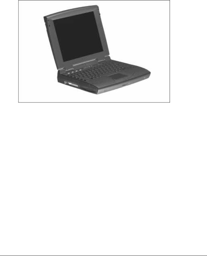
The Compaq Armada 1500 Family of Personal Computers is a line of multimedia notebook computers with advanced modularity, processors, and video graphics. This full-function, Pentium-based, family of notebook computers allows full desktop functionality and connectivity through the use of an optional Convenience Base. The following computer models are available:
Table 1-1
Compaq Armada Personal Computers
|
Pentium |
|
|
|
|
Level 2 |
|
|
|
|
Serial |
|||
Model |
Processor |
Display |
Hard Drive |
Cache |
CD-ROM |
Modem |
Configuration |
|||||||
|
|
|
|
|
|
|
|
|
|
|
|
|
|
|
1510 |
120-MHz |
11.3-inch CSTN |
1.0-GB |
|
|
|
|
|
|
BM51 |
||||
1510DM |
120-MHz |
11.3-inch CSTN |
1.0-GB |
|
|
|
■ |
|
■ |
BM52 |
||||
1520 |
133-MHz |
11.3-inch CSTN |
1.0-GB |
256-Kbyte |
|
|
|
|
BM53 |
|||||
1520D |
133-MHz |
11.3-inch CSTN |
1.0-GB |
256-Kbyte |
|
■ |
|
|
BM54 |
|||||
1520DM |
133-MHz |
11.3-inch CSTN |
1.0-GB |
256-Kbyte |
|
■ |
|
■ |
BM55 |
|||||
1550T |
133-MHz |
12.1-inch CTFT |
1.4-GB |
256-Kbyte |
|
|
|
|
BM56 |
|||||
1550DMT |
133-MHz |
12.1-inch CTFT |
1.4-GB |
256-Kbyte |
|
■ |
|
■ |
BM57 |
|||||
|
|
|
|
|
|
|
|
|
|
|
|
|
|
|
NOTE: All models have 16-MB of standard memory, upgradable to 80-MB.
Computer Product Description |
1-1 |
. . . . . . . . . . . . . . . . . . . . . . . . . . . . . . . . . . . . .
Figure 1-1. Compaq Armada Personal Computer
1.2 Standard Features
The Compaq Armada models have the following standard features:
■120or 133-MHz Pentium processors
■16-MB of EDO dynamic random access memory (DRAM), expandable to 80 MB
■1.4-GB or 1.0-GB, 2.5- inch with carrier, or 3-inch hard drive
■11.3-inch Color Super Twist Nematic CSTN, or 12.1-inch Color Thin Film Transistor (CTFT) SVGA displays
■Supports Lithium Ion (Li-ion) and Nickel Metal Hydride (NiMH) modular battery packs
■SoundBlaster−compatible audio controller with internal stereo speakers and internal microphone
■Full-size 101 key compatible keyboard including 12 function keys, 8 cursor control keys, inverted-T cursor control keys, and embedded numeric keypad
■Four user-programmable keys
■Touchpad pointing device
■Operates from an internal battery pack, plus an optional battery pack in the DualBay, or integrated AC power that is compatible with domestic or international power sources
■Power management and security features
1-2 Computer Product Description

. . . . . . . . . . . . . . . . . . . . . . . . . . . . . . . . . . . . .
■Infrared interface for wireless communication with other IrDA-compliant devices at data rates up to 4 mb/sec
■Two standard device slots that will accommodate two types I and II and one type III PC Cards, PCMCIA and CardBus cards; Compaq Telephony modem in the top slot and Zoomed-Video in the bottom slot
■176 pin expansion connector provides the interface to the convenience base options
■Rear-panel ports provide connections for parallel and serial, external monitor, keyboard/mouse, and IrDA compliant infrared devices
1.2.1Software Fulfillment
Replacement software may be ordered directly from Compaq Computer Corporation. Both the model and the serial numbers of the computer are needed to identify the specific software available.
Computer Product Description |
1-3 |

. . . . . . . . . . . . . . . . . . . . . . . . . . . . . . . . . . . . .
1.3 Options
The computer supports the following options:
■Convenience Base pass through model
■Convenience Base with Ethernet
■Memory expansion boards
■Li-ion and NiMH battery packs
■Automobile Adapter
■External Battery Charger
■PCMCIA modem
■AC power cords for international travelers
■Hard drive upgrade
■Internal modem
■Internal CD-ROM drive
1.3.1 Convenience Base
Compaq Armada models support the following convenience base models:
■Convenience base pass through
■Convenience base with Ethernet (RJ-45 and BNC connectors); BNC connector not available in North America
■Convenience base with Ethernet (BNC connector); not available in North America
1.3.2 System Memory Options
The computer supports optional 8-, 16-, 32-, and 64-MB memory boards. The memory boards are 60 ns EDO RAM without parity. System memory can be expanded to 80-MB of DRAM depending on the model.
1-4 Computer Product Description

. . . . . . . . . . . . . . . . . . . . . . . . . . . . . . . . . . . . .
1.3.3 External Battery Charger
The External Battery charger has the following features:
■Two battery charge slots
■Accepts both NiMH and Li-ion modular batteries
■Charges one battery in 1.5 hours
■Charges two batteries in 3 hours
1.3.4External Keyboards and Pointing Devices
Supports Compaq or Compaq compatible PS2 keyboards and pointing devices
1.3.5 External Monitors
The Compaq Armada models support all VGA Monitors up to 1024 x 768.
Computer Product Description |
1-5 |
. . . . . . . . . . . . . . . . . . . . . . . . . . . . . . . . . . . . .
1.4 External Computer Components
The external computer components are illustrated and described in this section.
1.4.1 Front and Left Side Components
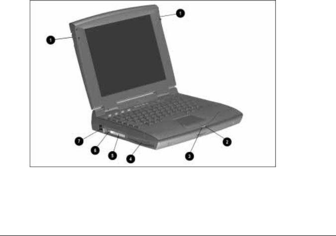
The front and left side external components are shown in the following figure and identified in this section:
1 Display latches
2 Battery charge light
3 Power/Suspend light
4 DualBay compartment
5 PC Card slots
6 PC Card eject levers
7 RJ-11 port (on some models)
Figure 1-2. Front and Left Side Components
1-6 Computer Product Description
. . . . . . . . . . . . . . . . . . . . . . . . . . . . . . . . . . . . .
1.4.2 Right Side Components
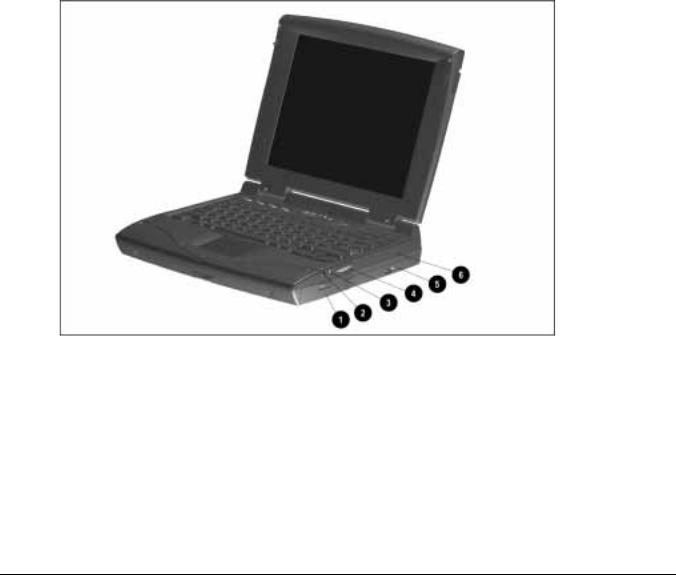
The right side external components are shown in the following figure and identified in this section:
1 Battery bay
2 Stereo/speaker headphone jack
3 Microphone jack
4 Volume control buttons
5 CD-ROM drive (on some models)
6 Cable lock provision
Figure 1-3. Right Side Components
Computer Product Description |
1-7 |
. . . . . . . . . . . . . . . . . . . . . . . . . . . . . . . . . . . . .
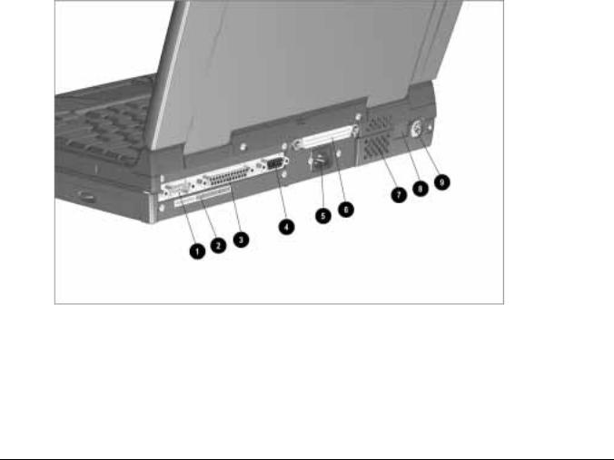
1.4.3 Rear Components
The rear components are shown in the following figure and identified in this section:
1 Serial connector
2 Serial number
3 Parallel connector
4 External monitor connector
5 AC Power connector
6 Docking connector
7 Airflow vents
8 Infrared port
9 Keyboard/Mouse connector
Figure 1-4. Rear Components
1-8 Computer Product Description
. . . . . . . . . . . . . . . . . . . . . . . . . . . . . . . . . . . . .
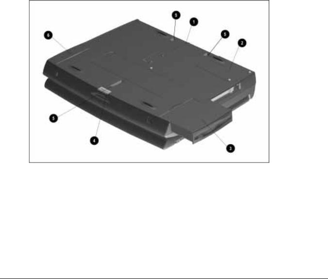
1.4.4 Bottom Components
The bottom external components are shown in the following figure and are identified in this section:
1 Docking alignment guide
2 Modem compartment
3 Diskette drive
4 Diskette drive release latch
5 Docking latch receptacles
6 Battery bay traction grip
Figure 1-5. Bottom Components
Computer Product Description |
1-9 |

. . . . . . . . . . . . . . . . . . . . . . . . . . . . . . . . . . . . .
1.4.5 Status Panel Lights
The status panel lights are shown in the following figure and are identified in this section:
1 Hard drive light
2 Diskette drive light
3 Num Lock light
4 Caps Lock light
5 Scroll Lock light
Figure 1-6. Status Panel Lights
1-10 Computer Product Description
. . . . . . . . . . . . . . . . . . . . . . . . . . . . . . . . . . . . .
Chapter 2
Convenience Base
Description
2.1 Models and Features
The convenience bases provide a permanent desktop solution for the computer by eliminating the need to disconnect external devices such as a printer, keyboard, or monitor when you undock the computer. All necessary connections and disconnections are made automatically when the computer is docked and undocked. The following convenience models are available:
Table 2-1
Compaq Armada 1500 Family of Convenience Bases
Model
Convenience Base Pass Through model
Convenience Base with Ethernet
Convenience Base with Ethernet, BNC model
Serial Configuration
BNH3
BNH1
BNH3
Convenience Base Description |
2-1 |
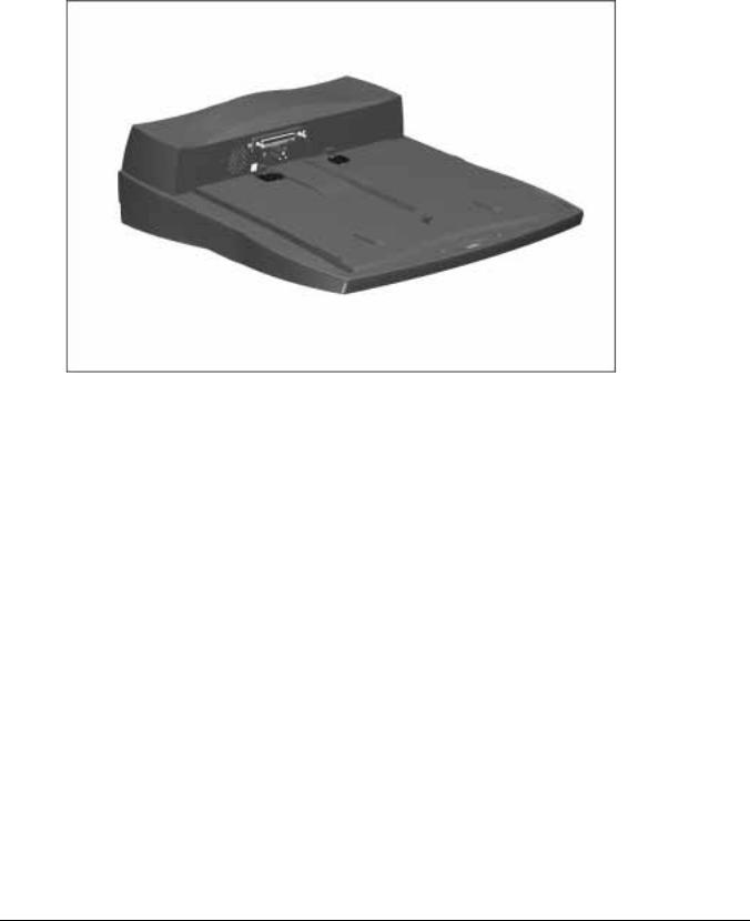
. . . . . . . . . . . . . . . . . . . . . . . . . . . . . . . . . . . . .
Figure 2-1. Compaq Armada 1500 Convenience Base
2-2 Convenience Base Description

. . . . . . . . . . . . . . . . . . . . . . . . . . . . . . . . . . . . .
2.2 Convenience Base Features
The Convenience Base pass through model and the convenience base with Ethernet model include the following features:
Convenience Base
pass through
Convenience Base
with Ethernet
Connections
Speaker/headphone |
|
■ |
|
■ |
Audio Line-In |
|
■ |
|
■ |
|
|
|
|
|
Serial |
|
■ |
|
■ |
|
|
|
|
|
Parallel |
|
■ |
|
■ |
|
|
|
|
|
External Monitor |
|
■ |
|
■ |
|
|
|
|
|
Keyboard |
|
■ |
|
■ |
|
|
|
|
|
Pointing Device |
|
■ |
|
■ |
|
|
|
|
|
MIDI/Joystick |
|
■ |
|
■ |
|
|
|
|
|
Other Features |
|
|
|
|
|
|
|
|
|
Cable lock provision |
|
■ |
|
■ |
|
|
|
|
|
Pass through AC Power |
|
■ |
|
■ |
|
|
|
|
|
BNC connector (not available in all countries) |
|
|
|
■ |
|
|
|
|
|
RJ-45 connector |
|
|
|
■ |
|
|
|
|
|
Options |
|
|
|
|
|
|
|
|
|
Monitor Stand |
|
■ |
|
■ |
|
|
|
|
|
Localized Power Cords |
|
■ |
|
■ |
|
|
|
|
|
Kensington lock |
|
■ |
|
■ |
|
|
|
|
|
Optional 100BaseT Ethernet Upgrade |
|
■ |
|
■ |
|
|
|
|
|
Convenience Base Description |
2-3 |

. . . . . . . . . . . . . . . . . . . . . . . . . . . . . . . . . . . . .
2.3 Convenience Base Components
The convenience base components are illustrated and described in this section.
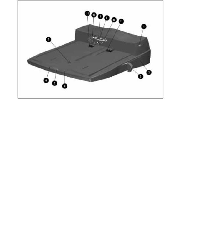
2.3.1 Front and Right Side Components
The front and right side convenience base components are shown and identified in this section.
1 Power button
2 Security cable lock provision
3 Docking lever
4 Battery charge light
5 Suspend button
6 Power/Suspend light
7 Retaining latch
8 Pass through AC power outlet
9 Docking connector
: Docking alignment pins
; Docking latches
2-4 Convenience Base Description
. . . . . . . . . . . . . . . . . . . . . . . . . . . . . . . . . . . . .
Figure 2-2. Convenience Base Front and Right Side Components
Convenience Base Description |
2-5 |

. . . . . . . . . . . . . . . . . . . . . . . . . . . . . . . . . . . . .
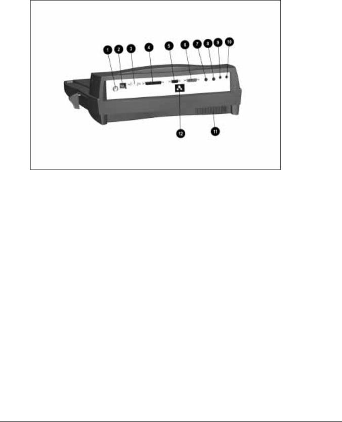
2.3.2 Rear Components
The rear components are shown in the following figure and identified in this section:
1 BNC connector (available on some models)
2 RJ-45 jack
3 Serial connector
4 Parallel connector
5 External monitor connector
6 MIDI/Joystick connector
7 Pointing device connector
8 Keyboard connector
9 Speaker/headphone jack
: Audio Line-in jack
; Fan
< AC power connector
2-6 Convenience Base Description
. . . . . . . . . . . . . . . . . . . . . . . . . . . . . . . . . . . . .
Figure 2-3. Convenience Base Rear Components
Convenience Base Description |
2-7 |

. . . . . . . . . . . . . . . . . . . . . . . . . . . . . . . . . . . . .
Chapter 3
Troubleshooting
This chapter contains troubleshooting information for the computer and the convenience base. The basic steps in troubleshooting the computer include:
1.Completing the preliminary steps listed in Section 3.1.
2.Running the Power-On Self-Test (POST) as described in Section 3.3.
3.Running Computer Setup as described in Section 3.5
4.Running the Computer Checkup (TEST) as described in Section 3.5.
5.Performing the recommended actions described in the diagnostic tables in Section 3.6 if you are unable to exercise POST or Computer Checkup or if the problem persists after running POST and Computer Checkup.
Follow these guidelines when troubleshooting:
■Complete the recommended actions in the order in which they are given.
■Repeat POST and Computer Checkup after each recommended action until the problem is resolved and the error message does not return.
■Once the problem is resolved, do not complete the remaining recommended actions.
■Refer to Chapter 7 for any removal and replacement procedures that are recommended for the computer. Refer to Chapter 8 for any removal or replacement procedures that are recommended for the convenience base.
■If the problem is intermittent, check the computer or convenience base several times to verify that the problem is solved.
Troubleshooting 3-1

. . . . . . . . . . . . . . . . . . . . . . . . . . . . . . . . . . . . .
Use the following table for quick reference to troubleshooting information:
If You Want To:
Check for POST error messages
Check that computer components are recognized and running properly
View information about the computer and installed or connected devices
Perform any of the following:
nCheck the system configuration
nSet the system power management parameters
nReturn the system to its original configuration
nCheck system configuration of installed devices
Run:
POST
Computer Checkup (TEST) under Compaq Utilities
View System Information
(INSPECT)under Compaq Utilities
Computer Setup
3.1 Preliminary Steps
IMPORTANT: Use AC Power when running POST, Computer Setup, or Computer Checkup. A low-battery condition could initiate Suspend or Hibernation and interrupt the test.
Before running POST and Computer Checkup, complete the following steps:
1.Obtain established passwords. If you must clear the passwords, go to Section 3.2.
2.Ensure that the hard drive is installed in the computer.
3.Ensure that the battery pack is installed in the computer and the AC power is connected to the computer and plugged into an AC power source.
4.Turn on the computer.
5.If a power-on password has been established, type the password and press Enter.
NOTE: The key icon appears on the display when the computer is turned on to indicate that QuickLock/QuickBlank has been initiated. Type the power-on password to
exit QuickLock/QuickBlank. If the password is unknown, it must be cleared (see Section 3.2).
6.Run Computer Setup (Section 3.5).
7.Use the Hotkeys to adjust the contrast (Fn+F9) and brightness (Fn+F10) to the center of their ranges and leave the display open. On models with color TFT displays, contrast is not applicable.
8.Turn off the computer and all external devices.
9.Disconnect any external devices that you do not want to test. If you want to use the printer to log error messages, leave it connected to the computer.
3-2 Troubleshooting

. . . . . . . . . . . . . . . . . . . . . . . . . . . . . . . . . . . . .
NOTE: If a problem only occurs when an external device is connected to the computer, the problem could be with the external device or its cable. Isolate the problem by running POST with and without the external device connected.
10.Use Advanced Diagnostics and loopback plugs in the serial and parallel connectors if you plan to test these ports. You may run Advanced Diagnostics from the hard drive or from a diskette.
If you are running Diagnostics from the hard drive, complete the following steps:
a.Turn on or restart the computer.
b.Press F10 when the cursor appears in the upper right corner of the screen. If you do not press F10 in time, restart the computer and try again. The Welcome screen appears.
If you are running Diagnostics from a diskette, complete the following steps:
a.Insert the Diagnostics diskette into the diskette drive and turn on the computer.
b.At the Welcome Screen, press Enter to accept OK.
c.Select Computer Checkup (TEST).
d.Select Prompted Diagnostics after "Identifying System Hardware" completes.
e.Select Interactive Testing and follow the displayed instructions.
Refer to Chapter 4 for the description and spare part number of the loopback plugs.
After completing the preliminary steps, run POST (Section 3.3) and Computer Checkup (Section 3.5).
3.2 Clearing the Power-On and Setup Passwords
The power-on password prevents use of the computer until the password is entered. The setup password prevents unauthorized changes to Computer Setup. To clear the passwords, you must remove all power from the system board. If you do not know the passwords, use the following procedure to clear the password:
1.Remove all battery packs from the battery bay and DualBay, if applicable.
2.Disconnect the AC power.
3.Remove the real time clock battery.
4.Wait five minutes.
5.Reconnect the AC power.
6.Restart the computer. During the Power-On Self Test (POST), a "162 System Options not Set" message appears. (See Section 3.4 for additional POST error messages).
7.Shut down the computer, then turn off the power again.
Troubleshooting 3-3
 Loading...