


 Loading...
Notice
The information in this guide is subject to change without notice.
Compaq Computer Corporation shall not be liable for technical or editorial errors or omissions contained herein; nor for incidental or consequential damages resulting from the furnishing, performance, or use of this material.
This guide contains information protected by copyright. No part of this guide may be photocopied or reproduced in any form without prior written consent from Compaq Computer Corporation.
Copyright 1996 Compaq Computer Corporation.
All rights reserved. Printed in the U.S.A.
Compaq, Deskpro, LTE, Contura, Presario, ProLinea, QuickLock, QuickBlank Registered U. S. Patent and Trademark Office. Contura Registered in the Philippines Patent Office.
Armada is a trademark of Compaq Computer Corporation
Microsoft, MS-DOS, and Windows are registered trademarks of Microsoft Corporation.
The software described in this guide is furnished under a license agreement or nondisclosure agreement. The software may be used or copied only in accordance with the terms of the agreement.
Product names mentioned herein may be trademarks and/or registered trademarks of their respective companies.
MAINTENANCE AND SERVICE GUIDE
COMPAQ ARMADA 1100 FAMILY OF PERSONAL COMPUTERS
First Edition (June 1996)
Spare Part Number 262489-001
Document Part Number 262471-001
Preface
This Maintenance and Service guide is a troubleshooting guide that can be used for reference when servicing the Compaq Armada 1100 Family of Personal Computers. Additional information is available in the SERVICE QUICK REFERENCE GUIDE and in QUICKFIND.
Compaq Computer Corporation reserves the right to make changes to the Compaq Armada 1100 Family of Personal Computers without notice.
Symbols
The following symbols and words mark special messages throughout this guide:
>>>>>>>>>>>>>>>>>>>>>>>>>>>>>>>>> WARNING <<<<<<<<<<<<<<<<<<<<<<<<<<<<<<<<<
Text set off in this manner indicates that failure to follow directions in the warning could result in bodily harm or loss of life.
>>>>>>>>>>>>>>>>>>>>>>>>>>>>>>>>>>>>><<<<<<<<<<<<<<<<<<<<<<<<<<<<<<<<<<<<<<
>>>>>>>>>>>>>>>>>>>>>>>>>>>>>>>>> CAUTION <<<<<<<<<<<<<<<<<<<<<<<<<<<<<<<<<
Text set off in this manner indicates that failure to follow directions could result in damage to equipment or loss of data.
>>>>>>>>>>>>>>>>>>>>>>>>>>>>>>>>>>>>><<<<<<<<<<<<<<<<<<<<<<<<<<<<<<<<<<<<<<
IMPORTANT: Text set off in this manner presents clarifying information or specific instructions.
NOTE: Text set off in this manner presents commentary, sidelights, or other points of information.
Technician Notes
>>>>>>>>>>>>>>>>>>>>>>>>>>>>>>>>> WARNING <<<<<<<<<<<<<<<<<<<<<<<<<<<<<<<<<
Only authorized technicians trained by Compaq should attempt to repair this equipment. All troubleshooting and repair procedures are detailed to allow only subassembly/module level repair. Because of the complexity of the individual boards and subassemblies, no one should attempt to make repairs at the component level or to make modifications to any printed wiring board. Improper repairs can create a safety hazard. Any indication of component replacement or printed wiring board modifications may void any warranty or exchange allowances.
>>>>>>>>>>>>>>>>>>>>>>>>>>>>>>>>>>>>><<<<<<<<<<<<<<<<<<<<<<<<<<<<<<<<<<<<<<
>>>>>>>>>>>>>>>>>>>>>>>>>>>>>>>>> CAUTION <<<<<<<<<<<<<<<<<<<<<<<<<<<<<<<<<
To properly ventilate your system, you must provide at least 3 inches (7.62 cm) of clearance on the front and back of the computer.
>>>>>>>>>>>>>>>>>>>>>>>>>>>>>>>>>>>>><<<<<<<<<<<<<<<<<<<<<<<<<<<<<<<<<<<<<<
>>>>>>>>>>>>>>>>>>>>>>>>>>>>>>>>> WARNING <<<<<<<<<<<<<<<<<<<<<<<<<<<<<<<<<
The computer is designed to be electrically grounded. To ensure proper operation, plug the AC power cord into a properly grounded electrical outlet only.
>>>>>>>>>>>>>>>>>>>>>>>>>>>>>>>>>>>>><<<<<<<<<<<<<<<<<<<<<<<<<<<<<<<<<<<<<<
Serial Number
The serial number is displayed on the bottom of the CPU next to the memory compartment cover.
Locating Additional Information
The following documentation is available to support these products: o Quick Setup
o Reference Guide
o Introducing Microsoft Windows 95
o Compaq Service Quick Reference Guide
o Service Training Guides
o Compaq Service Advisories and Bulletins
o Compaq QuickFind
o Technical Reference Guide

Chapter 1 - Product Description
Computer Features and Models
The Compaq Armada 1100 Family of Personal Computers is a line of full-featured, Pentium-based portable computers. The following models are available:
o Compaq Armada 1110
o Compaq Armada 1120 and Armada 1125
o Compaq Armada 1120T
This chapter describes the model offerings and features of the computers.
Models
The Compaq Armada 1100 Family of Personal Computers is available in the models shown in Table 1-1.
Table 1-1. Compaq Armada 1100 Family Models
===========================================================================
Model Processor Display Hard Drive
===========================================================================
Armada 1110 75-MHz Pentium 10.4-inch CSTN 810 MB
---------------------------------------------------------------------------
Armada |
1120 |
100-MHz Pentium |
10.4-inch CSTN |
810 MB |
Armada |
1125 |
|
|
|
---------------------------------------------------------------------------
Armada 1120T 100-MHz Pentium 10.4-inch CTFT 810 MB
===========================================================================
Standard Features
The computers have the following standard features:
o 75 or 100-MHz Pentium processors
o 8 MB of dynamic random access memory (DRAM), expandable to 24 MB
o 810 MB hard drive
o 10.4-inch Color Super Twist Nematic (CSTN) or 10.4-inch Color Thin Film Transistor (CTFT) VGA displays
o Nickel metal hydride (NiMH) battery pack
o Full-size 101-key compatible keyboard, including 12 function keys and embedded numeric keypad
o Integrated trackball
o Operates from an internal battery pack or an AC adapter that is compatible with domestic or international power sources
o Power management and security features
o Two PCMCIA standard device sockets that will accommodate Types I, II, and III PC Cards
o Rear panel ports provide connectors for parallel and serial ports, video out, and keyboard/mouse port
Software Fulfillment
Backup software may be ordered directly from Compaq Computer Corporation through the Compaq Order Center. In Europe backup software may be ordered using the Software Diskette Order Form which is included in the For Help... booklet. Both the model and serial numbers of the computer are needed to identify the specific software available.
For technical questions about software for the computer, contact a Compaq Technical Support Engineer. The model and serial numbers of the computer should be available before making the call.
Security Features
The computer has the following security features:
o Ability to secure the computer to an immovable object with an optional cable lock.
o Ability to establish power-on and setup passwords.
o Ability to disable the following devices from the Security menu in Computer Setup: serial port, parallel port, PC Card slots, diskette drive, diskette drive boot ability.
Power Management
The computer supports three power management modes:
o Local Standby: The ability to send individual subsystems into reduced power modes after predetermined periods of inactivity.
o Global Standby: The ability to place all subsystems in a reduced power mode after a predetermined period of inactivity.
o Hibernation: The ability to save the system configuration and user data to the hard disk, for restoration at a later time.
The OFF and ON states also involve power management. In the OFF state, the computer appears to be consuming no power; however, as long as there is a battery capable of supplying current, some components will be powered up, performing housekeeping tasks and waiting to be awakened. In the ON state, all systems are powered up and the unit is completely functional.
Computer Options
The options for the computer that are available from Compaq are described in the following sections.
System Memory Options
The system memory options that are available from Compaq for the computers are 8 and 16 MB memory expansion boards. The memory expansion boards are 70-ns Fast Page Mode DRAM SODIMMs, without parity. Maximum memory is 24 MB of DRAM.
The expansion memory connector is a 144-pin SODIMM socket. Either parity or non-parity SODIMMs may be used, but parity checking will not be enabled by the memory controller.
Miscellaneous Options
The following options for the computer are also available from Compaq:
o AC Adapter
o Automobile Adapter
o Extended Life NiMH battery pack
o Slipcase
o AC power cords for international travelers

AC Adapter
The AC adapter supplies DC voltage to the system converter to operate and/or charge the installed battery pack. The adapter provides sufficient power to charge the battery pack in 1.5 hours or less with the system off, or in 3.5 hours or less with the system on. The AC adapter power specifications are presented in Chapter 7.
Automobile Adapter
The automobile adapter is used to charge the computer while traveling in an automobile. The Auto Adapter power specifications are presented in Chapter 7.
Nickel Metal Hydride Battery Pack
Nickel metal hydride battery packs are available for use with the Compaq Armada 1100 Family of Personal Computers.
External Computer Components
The external computer components are shown and described in this section.
Front and Left Side Components
The front and left side external components are shown in the following figure and described in this section:
[1]Handle bracket (2)
[2]Keyboard tilt feet
[3]Diskette drive
[4]PC Card slots
[5]Display latches (2)
[6]PC Card release levers
[7]Battery compartment button
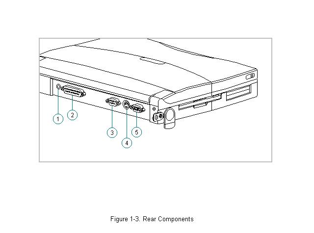
Rear Components
The rear components are shown in the following figure and identified in this section:
[1]Power connector
[2]Parallel connector
[3]Serial connector
[4]Keyboard/mouse connector
[5]External monitor connector

Bottom Components
The bottom external components are shown in the following figure and are identified in this section:
[1]Battery compartment
[2]Memory compartment

Status Panel Lights
The status panel lights are shown in the following figure and are identified in this section:
[1]Power/standby
[2]Battery charge
[3]Hard drive
[4]Diskette drive
[5]Battery gauge
[6]Caps Lock
[7]Scroll Lock
[8]Num Lock
System Design
This section provides an overview of the system design.
System Board and Processor
The OPTi-designed Viper-N Chipset provides PCI bus, ISA bus, cache controller, memory controller, and peripherals controller:
o OPTi 82C557M System Controller
o OPTi 82C556M Data Buffer Controller
o OPTi 82C558E Integrated Peripherals Controller
The computer supports a 75-MHz (P54C) CPU at 50-MHz bus speed, and a 100-MHz (P54LM) CPU at 66-MHz bus speed. Bus speed and processor core voltage are configurable through resistor values at manufacturing. The processor is soldered to the system board and is not removable.
System Memory Options
The main memory subsystem supports a standard 8 MB DRAM, expandable to a maximum of 24 MB. The standard memory is soldered onto the system I/O board. Expansion memory is available in 8 or 16 MB increments.
Diskette Drive
The computer uses a standard 3.5-inch, 1.44 MB diskette drive. The system supports a single diskette drive in the computer.
Hard Drive
The computer supports an IDE hard drive. Cable select technology is employed for device 0/device 1 selection. The hard drive mounts to the system board with a hard drive bracket and connects directly to the system board. A screw secures the hard drive bracket in place.
Computer Design Overview
This section presents a brief design overview of the computer. See Chapter 3 for an overview of the system unit and the display assembly from the perspective of replacing components in the field. All replacement parts are listed in Chapter 3, and removal and replacement procedures are presented in Chapter 5.
The computer is a traditional clam shell design with a display unit and a system unit. The computer opens to reveal a backlighted LCD display and a full-sized keyboard. The display is designed to open to 135o.
System Unit
The major components of the system unit are: the CPU cover, keyboard, system board with processor, hard drive, diskette drive, memory expansion board, battery pack and compartment, integrated trackball assembly, Real-Time Clock battery, and PC Card (PCMCIA) ejector rails and components.
Display Unit
The standard video subsystem consists of one of the following internal LCD displays:
o 10.4-inch VGA CSTN display panel
o 10.4-inch VGA CTFT display panel
In addition, the video subsystem consists of:
o Cirrus Viking PCI Bus Graphics Accelerator with 1 MB EDO (two 70-ns 256kx 16) VRAM
o An inverter to supply AC power to the LCD backlight system
o A standard external VGA connector for use with CRTs and other VGA compatible displays; also supported: external SVGA (maximum resolution 1024 x 768 x 256)
o A flex cable connecting the system board to the LCD display and the inverter
o 48 KB of video ROM integrated into system ROM
Chapter 2 - Troubleshooting
Introduction
This chapter contains troubleshooting information for the computer. The basic steps in troubleshooting include:
1.Completing the preliminary steps listed in Section 2.1.
2.Running the Power-On Self-Test (POST) as described in Section 2.4.
3.Running the Computer Checkup (TEST) as described in Section 2.5.
4.Performing the recommended actions described in the diagnostic tables in Section 2.7 if you are unable to exercise POST or Computer Checkup or if the problem persists after running POST and Computer Checkup.
Adhere to the following guidelines when troubleshooting:
o Complete the recommended actions in the order in which they are given.
o Repeat POST and Computer Checkup after each recommended action until the problem is resolved and the error message does not return.
o Once the problem is resolved, do not complete the remaining recommended actions.
o Refer to Chapter 5 for any removal and replacement procedures that are recommended.
Preliminary Steps
IMPORTANT: Use the AC adapter when running POST, Computer Setup, or Computer Checkup. A low battery condition could initiate Standby and interrupt the test.
Before running POST and Computer Checkup, complete the following steps:
1.If a power-on password has been established, type the password and press Enter.
NOTE: The key icon appears on the status display when the computer is turned on to indicate that QuickLock/QuickBlank has been initiated. Type the power-on password to exit QuickLock/QuickBlank. If the password is unknown, it must be cleared (see Section 2.2).
2.Run Computer Setup (Section 2.3).
3.Use the Hotkeys to adjust the brightness (Fn+F9) and contrast (Fn+F10) to the center of their ranges and leave the display open. On models with color TFT displays, contrast is not adjustable.
4.Turn off the computer and all external devices.
5.Disconnect any external devices that you do not want to test. If you want to use the printer to log error messages, leave it connected to the computer.
NOTE: If a problem only occurs when an external device is connected to the
computer, the problem could be with the external device or its cable. Isolate the problem by running POST with and without the external device connected.
6.Use Advanced Diagnostics and loopback plugs in the serial and parallel connectors if you plan to test these ports. To run Advanced Diagnostics, complete the following steps:
a.Insert the Diagnostics diskette into the diskette drive and turn on the computer.
b.At the Welcome Screen, enter Ctrl+A.
c.Press Enter to accept OK.
d.Select Computer Checkup (TEST).
e.Select Prompted Diagnostics after "Identifying System Hardware" completes.
f.Select Interactive Testing and follow the displayed instructions.
7.Ensure that the battery pack is installed in the computer and the AC adapter is connected to the computer and plugged into an AC power source.
After completing the preliminary steps, run POST (Section 2.4) and Computer Checkup (Section 2.5).
Running Computer Setup
The ROM-based Computer Setup displays the current system configuration and allows you to set system and power management parameters. These parameters are stored in CMOS, and a backup copy is saved in a parameter block in system flash ROM.
You can access Computer Setup by pressing F10 when the prompt appears after you turn on the computer. The following configuration parameters can be changed in Computer Setup:
o Power conservation (when)
o Power conservation (level)
o Hibernation on/off
o Hibernation settings
o Warning beep
o Setup password
o Diskette drive disable
o Serial ports disable
o Parallel port disable
o PC Card slots disable
o Resume password on/off
o Boot memory test
o Keyboard numlock
o Boot sequence
o Boot display
o Serial port settings
o Parallel port settings
o Power-on password
o Diskette drive boot disable
To run Computer Setup, complete the following steps:
Computer Setup automatically recognizes and configures the system for new Compaq devices. It does this without prompting you for information about the devices. However, if you add a memory expansion board, a prompt appears the next time you turn on the computer, notifying you of the new memory configuration.
The first Computer Setup screen displays current settings for the system, ports, and devices. The status bar at the bottom of the screen gives instructions for navigating and choosing options. The status bar also displays descriptions as you highlight menus and menu options.
NOTE: If the main system board is replaced, the serial number on this screen changes to 0 (zero).
Select one of the menus from the menu bar at the top of the screen to view or to change the following configuration settings:
o Initialization startup preferences
o Ports, including serial and parallel
o Power, including Power Management and Hibernation
o Security, including setup and power-on passwords and device disabling
Initialization Menu
Select the Initialization menu to change the initialization (startup) settings for running the POST memory tests, numlock on or off, the drive boot sequence, and the active display.
Ports Menu
Select the Ports menu to change the default input/output (I/O) addresses and interrupt requests (IRQs) for serial and parallel ports.
NOTE: If you select conflicting settings for the ports, the system automatically changes one of the settings.
Power Menu
Select the Power menu to enable or disable Power Management, low-battery warning beeps, and an external energy-saving monitor. The factory default settings are:
o Power Management Enabled While on Battery
o Conservation Level Medium
o Low-Battery Warning Beeps Enabled
o External Energy Saving Monitor Disabled
>>>>>>>>>>>>>>>>>>>>>>>>>>>>>>>>> CAUTION <<<<<<<<<<<<<<<<<<<<<<<<<<<<<<<<<
If you disable Power Management or Hibernation, you must take immediate action to resolve a low-battery condition to prevent losing unsaved information.
>>>>>>>>>>>>>>>>>>>>>>>>>>>>>>>>>>>>><<<<<<<<<<<<<<<<<<<<<<<<<<<<<<<<<<<<<<
If you elect to disable the low-battery warning beeps, a low-battery condition is indicated only by a blinking battery light. If you disable Power Management or Hibernation, information in memory is not automatically saved during a critical low-battery condition.
If you enable the selection for an external energy-saving monitor, it enters low-power mode when the screen timeout occurs. If you enable this selection and do not have an energy-saving monitor, the screen display may become distorted.
Under Power Management, you can select whether to enable Power Management while on AC or battery power, only while on battery power, or never (disabled).
If you enable Power Management, you can select from four conservation levels: high, medium, none (drain), or custom. The conservation level sets the timeouts for Standby, Hibernation, drives, and screens. A timeout is a period of inactivity after which power is turned off to the system or component.
o High: Provides the maximum amount of power conservation and the maximum battery operating time from a single charge.
o Medium (default): Provides a balance between performance and battery life.
o Custom: Conserves power according to specified timeout settings.
o None (Drain): Provides no power conservation features; the system runs at full speed.
Security Menu
Select the Security menu to set, change, or delete the setup and power-on passwords and to enable/disable QuickLock/QuickBlank, power-on password from Standby, diskette drives, ports, and PC Card slots.
Setup Password
Use the Setup password to protect the system configuration from unauthorized changes. After you establish the setup password, you cannot change the system configuration until you enter the setup password.
IMPORTANT: Type carefully because the password does not display as you type it. If you choose to, you can use the same password for setup and for power-on.
The next time you press F10 (after POST) to run Computer Setup, a password prompt appears on the screen. If you enter the password incorrectly, you are prompted to reenter the password.
If you forget the setup password, you cannot change the system configuration until the computer memory is cleared of the password. Refer to Section 2.2 in this guide for procedures for clearing the password.
>>>>>>>>>>>>>>>>>>>>>>>>>>>>>>>>> CAUTION <<<<<<<<<<<<<<<<<<<<<<<<<<<<<<<<<
Record your setup password and put it in a safe place. If you forget your setup password, you cannot reconfigure the computer until the computer memory is cleared of the password.
>>>>>>>>>>>>>>>>>>>>>>>>>>>>>>>>>>>>><<<<<<<<<<<<<<<<<<<<<<<<<<<<<<<<<<<<<<
Power-On Password
The power-on password prevents use of the computer until the password is entered. After you establish the power-on password, you must enter it whenever you turn on the computer.
IMPORTANT: Type carefully because the password does not display as you type it. If you choose to, you can use the same password for setup and for power-on.
You can also select to require the power-on password when exiting Standby.
The next time you start the computer or exit Standby, a password prompt appears. If you enter the password incorrectly, you are prompted to reenter the password.
If you forget the power-on password, you cannot use the computer until the computer memory is cleared of the password. Refer to Section 2.2 in this guide for procedures for clearing the password.
>>>>>>>>>>>>>>>>>>>>>>>>>>>>>>>>> CAUTION <<<<<<<<<<<<<<<<<<<<<<<<<<<<<<<<<
Record the power-on password and put it in a safe place. If you forget your power-on password, you cannot use the computer until the computer memory is cleared of the password.
>>>>>>>>>>>>>>>>>>>>>>>>>>>>>>>>>>>>><<<<<<<<<<<<<<<<<<<<<<<<<<<<<<<<<<<<<<
QuickLock/QuickBlank
Enabling QuickLock/QuickBlank allows you to temporarily disable the keyboard and clear the screen until the power-on password is entered. After you have enabled QuickLock/QuickBlank, you can initiate it at any time by pressing the Fn+F6 hotkey.
When QuickLock/QuickBlank is initiated, the key icon on the status panel turns on. Type the power-on password on the blank screen to exit QuickLock/QuickBlank.
Disabling Devices
The Security Menu provides a way to disable the following devices:
o Serial port
o Parallel port
o PC Card slots
o Diskette drive
Disabling these devices prevents the unauthorized transfer of data using the devices. To reenable a device, deselect the Disable option and restart the computer.
Exit Menu
The Exit menu has four options:
o Save and Exit: Saves configuration changes, but some changes do not take effect until the computer is restarted.
o Exit (No Save): Exits and does not save the changes you have made.
o Restore Factory Defaults: Replaces the current configuration settings with the original factory default settings.
POST Error Messages
This chapter contains typical error messages that you may encounter during the power-on self-test (POST). POST is a series of tests that run every time you turn on the computer. POST verifies that the system is configured and functioning properly. A successful POST is followed by one or two short beeps.
If you receive an error message listed on the following pages, follow the recommended action. If you receive an error message that is not listed, run Computer Checkup from the Diagnostics diskette. Information about running Computer Checkup is presented later in this chapter.
If POST detects an error, one of the following events occurs:
o A message with the prefix "WARNING" appears informing you where the error occurred. The system pauses until you press F1 to continue.
o A message with the prefix "FATAL" appears informing you where the error occurred. After the message, the system emits a series of audible beeps. The system then stops.
o The system emits a series of audible beeps. The system then stops.
Warning messages indicate a potential problem exists such as a system configuration error. When F1 is pressed, the system should resume. You should be able to correct problems that produce WARNING messages.
IMPORTANT: When a WARNING message includes the prompt to "RUN SCU," run Computer Setup. (Computer Setup replaces the SCU utility.)
Fatal errors emit a beep and may display a FATAL message. Fatal errors indicate severe problems, such as a hardware failure. Fatal errors do not allow the system to resume. Some of the Fatal error beep codes are listed at the end of this section.
Table 2-1. Warning Messages
===========================================================================
Message Description
===========================================================================
Clock not ticking correctly The real time clock is not ticking.
---------------------------------------------------------------------------
CMOS checksum invalid, run |
CMOS RAM |
information has been corrupted and |
SCU |
needs to |
be reinitialized by running Computer |
Setup.
---------------------------------------------------------------------------
CMOS failure, run SCU CMOS RAM has lost power and needs to be reinitialized by running Computer Setup.
---------------------------------------------------------------------------
Floppy controller failed |
The diskette drive controller failed to |
|
respond to the reset command. Power down the |
|
system and check all appropriate connections. |
|
If the diskette drive controller continues to |
fail, you may need to replace the system board.
---------------------------------------------------------------------------
Floppy disk track 0 failed |
The diskette drive cannot read track 0 of the |
|
diskette in the drive. Try another diskette. |
|
If the problem persists, you may need to |
|
replace the diskette drive. |
---------------------------------------------------------------------------
Floppy information invalid, |
The drive parameters stored in CMOS RAM do |
run SCU |
not match the diskette drives detected in the |
|
system. Run Computer Setup |
---------------------------------------------------------------------------
Hard disk controller error |
The hard drive controller failed to respond |
|
to the reset command. Check the drive |
|
parameters. Power down the system and check |
|
all appropriate connections. |
---------------------------------------------------------------------------
Hardware information does |
The video adapter type specified in CMOS RAM |
not match video card, run |
does not match the installed hardware. Run |
SCU |
Computer Setup |
---------------------------------------------------------------------------
Keyboard controller failure The keyboard failed the self-test command.
---------------------------------------------------------------------------
Keyboard failure |
The keyboard failed to respond to the RESET |
|
ID command. |
---------------------------------------------------------------------------
No interrupts from Timer 0 The periodic timer interrupt is not occurring.
---------------------------------------------------------------------------
RAM parity error at |
A RAM |
parity error occurred at the specified |
location xxxx |
(hex) |
location. |
---------------------------------------------------------------------------
ROM at xxxx (LENGTH yyyy) An illegal adapter ROM was located at the with nonzero checksum (zz) specified address. An external adapter (such
as a video card) may be causing the conflict.
---------------------------------------------------------------------------
Time/Date corrupt - run SCU The time and date stored in the real time clock have been corrupted, possibly by a power loss. Run Computer Setup.
---------------------------------------------------------------------------
Unexpected amount of |
The amount of memory detected by POST does |
memory, run SCU |
not match the amount specified in CMOS RAM. |
|
Run Computer Setup. |
---------------------------------------------------------------------------
Hard disk xx failure |
A failure or an |
error occurred when trying to |
(or error) |
access the hard |
drive. |
===========================================================================
Table 2-2. Fatal Error Messages |
|
|
=========================================================================== |
||
Message |
Description |
Beep Code |
=========================================================================== |
||
CMOS RAM test failed |
A walking bit test of CMOS RAM |
|
|
location 0E (Hex) - 3F (Hex) failed. |
3 |
--------------------------------------------------------------------------- |
||
DMA controller faulty |
A sequential read/write of the |
|
|
transfer count and transfer address |
|
|
registers within the primary and |
|
|
secondary DMA controllers failed. |
4 |
--------------------------------------------------------------------------- |
||
Faulty DMA page |
|
|
registers |
A walking bit read/write of the 16 DMA |
|
|
controller page registers starting at |
|
|
location 80 Hex failed. |
0 |
--------------------------------------------------------------------------- |
||
Faulty refresh |
|
|
circuits |
A continuous read/write test of port |
|
|
61h found that bit 4 (Refresh Detect) |
|
|
failed to toggle within an allotted |
|
|
amount of time. |
1 |
--------------------------------------------------------------------------- |
||
Interrupt controller |
|
|
failed |
A sequential read/write of various |
|
|
Interrupt Controller registers failed. |
5 |
--------------------------------------------------------------------------- |
||
ROM checksum incorrect |
A checksum of the ROM BIOS does not |
|
|
match the byte value at F000:FFFF. |
2 |
--------------------------------------------------------------------------- |
||
RAM error at location |
|
|
xxxx |
RAM error occurred during memory test. |
None |
--------------------------------------------------------------------------- |
||
Parity error at |
|
|
unknown location |
Parity error occurred. |
None |
=========================================================================== |
||
The following table lists some of the Fatal Error beep codes, along with the beep sequence (short, long, pause) and the meaning of the beeps.
Table 2-3. Fatal Error Beep Codes
===========================================================================
Beep Code Beep Sequence Explanation Remedy
===========================================================================
0 |
S-S-S-P-S-S-L-P |
The DMA page |
|
|
|
registers are faulty. |
Replace system board. |
1 |
S-S-S-P-S-L-S-P |
The refresh circuitry |
|
|
|
is faulty. |
Replace system board. |
2 |
S-S-S-P-S-L-L-P The ROM checksum is |
1. Flash the ROM |
|
|
|
incorrect. |
2. Replace system |
|
|
|
board. |
3 |
S-S-S-P-L-S-S-P |
The CMOS RAM test |
|
|
|
failed. |
Replace system board. |
4 |
S-S-S-P-L-S-L-P The DMA controller is |
|
|
|
|
faulty. |
Replace system board. |
5 |
S-S-S-P-L-L-S-P |
The interrupt |
|
|
|
controller failed. |
Replace system board. |
6 |
S-S-S-P-L-L-L-P |
The keyboard |
|
|
|
controller failed. |
Replace system board. |
7 |
S-S-L-P-S-S-S-P |
Graphics adapter is |
|
|
|
faulty. |
Replace system board. |
8 |
S-S-L-P-S-S-L-P |
Internal RAM is |
|
|
|
faulty. |
Replace processor |
|
|
|
board. |
---------------------------------------------------------------------------
S = Short, L = Long, P = Pause
===========================================================================
Compaq Diagnostics
Run the Compaq Diagnostics utilities diskette when you want to view or test system information and installed or connected devices. The Diagnostics menu includes the following utilities:
o Computer Checkup (TEST)
o View System Information (INSPECT)
o Prepare Computer for a Compaq Service Call (RemotePaq)
If you have a problem you cannot solve, run the Diagnostics utilities before you call for support. Run Computer Checkup and select to save the device list to a file and to print or to save the log of errors. Run the View System Information (INSPECT) utility and select to print or to save that information. Have the files or the printed information available when you call for support.
Computer Checkup (TEST)
Computer Checkup (TEST) determines whether the various computer components and devices are recognized by the system and are functioning properly. You can display, print, or save the information generated by Computer Checkup.
Follow these steps to run Computer Checkup:
1.Plug the computer into an external power source. (A low battery condition could interrupt the program.)
2.Turn on the external devices that you want to test. Connect the printer if you want to print a log of error messages.
3.Insert the Compaq Diagnostics diskette in drive A.
4.Turn on or restart the computer. The computer starts from drive A, and the Diagnostics Welcome screen appears.
5.Press Enter to continue. The Diagnostics menu appears.
6.Select Computer Checkup from the Diagnostics menu. A Test Option menu appears.
7.Select "View the Device List" from the Test Option menu. A list of the installed Compaq devices appears.
8.If the list of installed devices is correct, select OK. The Test Option menu appears.
NOTE: If the list is incorrect, ensure that any new devices are installed properly.
9.Select one of the following from the Test Option menu:
o Quick Check Diagnostics. Runs a quick, general test on each device with a minimal number of prompts. If errors occur, they display when the testing is complete. You cannot print or save the error messages.
o Automatic Diagnostics. Runs unattended, maximum testing of each device with minimal prompts. You can choose how many times to run the tests, to stop on errors, or to print or save a log of errors.
o Prompted Diagnostics. Allows maximum control over testing the devices. You can choose attended or unattended testing, decide to stop on errors, or choose to print or save a log of errors.
10.Follow the instructions on the screen as the devices are tested. When testing is complete, the Test Option menu appears.
11.Exit the Test Option menu.
12.Exit the Diagnostics menu.
View System Information (INSPECT)
The View System Information (INSPECT) utility provides information about the computer and installed or connected devices. You can display, print, or save the information.
Follow these steps to run INSPECT from the Compaq Diagnostics diskette:
1.Turn on the external devices that you want to test. Connect the printer if you want to print the information.
2.Insert the Compaq Diagnostics diskette into drive A.
3.Turn on or restart the computer. The computer starts from drive A, and the Diagnostics Welcome screen appears.
4.Press Enter to continue. The Diagnostics menu appears.
5.Select View System Information (INSPECT) from the Diagnostics menu.
6.Select the item you want to view from the following list:
===========================================================================
System Memory
===========================================================================
ROM |
Audio |
Keyboard |
Operating system |
System ports |
System files |
System storage |
Windows files |
Graphics
===========================================================================
7.Follow the instructions on the screen to cycle through the screens, to return to the list and choose another item, or to print the information.
RemotePaq
This utility is only available in certain geographical areas and requires a modem. It allows a Compaq reseller or service provider to automatically run diagnostics on the computer.
To run RemotePaq, follow these steps:
1.Insert the Compaq Diagnostics diskette into drive A.
2.Turn on or restart the computer. The computer starts from drive A, and the Diagnostics Welcome screen appears.
3.Press Enter to continue. The Diagnostics menu appears.
4.Select Prepare Computer for a Compaq Service Call (RemotePaq).
5.Follow the instructions on screen.
Diagnostic Error Codes
Diagnostic error codes occur if the system recognizes a problem while running the Compaq Diagnostic program. These error codes help identify possibly defective subassemblies.
Tables 2-4 through 2-13 list possible error codes, a description of the error condition, and the action required to resolve the error condition.
IMPORTANT: Retest the system after completing each step. If the problem has been resolved, do not proceed with the remaining steps.
For assistance in the removal and replacement of a particular subassembly, see Chapter 5, "Computer Removal and Replacement Procedures."
Table 2-4. Processor Test Error Codes
===========================================================================
Error Code Description Recommended Action
===========================================================================
101 |
- xx |
CPU test failed |
The following applies to error codes |
|
|
|
101 - xx through 113 - xx: |
103 |
- xx |
DMA page registers |
|
|
|
test failed |
Replace the system board and retest. |
104 |
- xx |
Interrupt controller |
|
|
|
master test failed |
|
105 |
- xx |
Port 61 error |
|
106 |
- xx |
Keyboard controller |
|
|
|
self-test failed |
|
107 |
- xx |
CMOS RAM test |
|
|
|
failed |
|
108 |
- xx |
CMOS interrupt test |
|
|
|
failed |
|
109 |
- xx |
CMOS clock test |
|
|
|
failed |
|
110 |
- xx |
Programmable timer |
|
|
|
load data test |
|
|
|
failed |
|
113 - xx Protected mode test failed
---------------------------------------------------------------------------
114 - 01 Speaker test failed 1. Check system configuration.
2.Verify cable connections to speaker.
3.Replace the system board and retest.
===========================================================================
Table 2-5. Memory Test Error Codes
===========================================================================
Error Code Description Recommended Action
===========================================================================
200 |
- xx |
Memory machine ID |
The following steps apply to error |
|
|
|
test failed |
codes 200 - xx and 202 - xx: |
|
202 |
- xx |
Memory system ROM |
1. |
Flash the system ROM and retest. |
|
|
checksum failed |
2. |
Replace the system board and retest. |
---------------------------------------------------------------------------
203 |
- xx |
Write/Read test |
The following steps apply to error |
|
|
|
failed |
codes 203 - xx through 215 - xx: |
|
204 |
- xx |
Address test failed |
1. |
Remove the memory module and retest. |
|
|
|
2. |
Install a new memory module and |
211 |
- xx |
Random pattern test |
|
retest. |
|
|
failed |
|
|
214 |
- xx |
Noise test failed |
|
|
215 - xx Random address test failed
===========================================================================
Table 2-6. Keyboard Test Error Codes
===========================================================================
Error Code Description Recommended Action
===========================================================================
300 |
- xx |
Failed ID Test |
The following steps apply to error |
|
|
|
|
codes 300 - xx through 304 - xx: |
|
301 |
- xx |
Failed Self-test/ |
1. |
Check the keyboard connection. If |
|
|
Interface Test |
|
disconnected, turn off the computer |
|
|
|
|
and connect the keyboard. |
|
|
|
2. |
Replace the keyboard and retest. |
302 |
- xx |
Failed Individual |
3. |
Replace the system board and retest. |
|
|
Key Test |
|
|
304 - xx Failed Keyboard Repeat Test
===========================================================================
Table 2-7. Parallel Printer Test Error Codes
===========================================================================
Error Code Description Recommended Action
===========================================================================
401 |
- xx |
Printer failed or |
The following steps apply to error |
|
|
|
not connected |
codes 401 - xx through 403 - xx: |
|
402 |
- xx |
Failed Port Test |
1. |
Connect the printer. |
|
|
|
2. |
Check power to the printer. |
403 |
- xx |
Printer pattern test |
3. |
Install the loopback connector and |
|
|
failed |
|
retest. |
|
|
|
4. |
Check port and IRQ configuration. |
|
|
|
5. |
Replace the system board and retest. |
===========================================================================
Table 2-8. Diskette Drive Test
===========================================================================
Error Code Description Recommended Action
===========================================================================
600 |
- xx |
Diskette ID drive |
The following steps apply to error |
|
|
types test failed |
codes 600 - xx through 698 - xx: |
601 |
- xx |
Diskette format |
1. Replace the diskette media and |
|
|
failed |
retest. |
|
|
|
2. Check and/or replace the diskette |
602 |
- xx |
Diskette read test |
power and signal cables and retest. |
|
|
failed |
3. Replace the diskette drive and |
|
|
|
retest. |
603 |
- xx |
Diskette write, |
4. Replace the system board and |
|
|
read, compare test |
retest. |
|
|
failed |
|
604 |
- xx |
Diskette random |
|
|
|
read test failed |
|
605 |
- xx |
Diskette ID media |
|
|
|
failed |
|
606 |
- xx |
Diskette speed test |
|
|
|
failed |
|
609 |
- xx |
Diskette reset |
|
|
|
controller test |
|
|
|
failed |
|
610 |
- xx |
Diskette change |
|
|
|
line test failed |
|
697 |
- xx |
Diskette type error |
|
698 |
- xx |
Diskette drive speed |
|
not within limits
---------------------------------------------------------------------------
699 - xx |
Diskette drive/media |
1. |
Replace media. |
|
ID error |
2. |
Run the Configuration and |
|
|
|
Diagnostics Utilities. |
===========================================================================
Table 2-9. Serial Test Error Codes
===========================================================================
Error Code Description Recommended Action
===========================================================================
1101 - xx |
Serial port test |
1. |
Check port configuration |
|
failed |
2. |
Replace the system board and retest. |
===========================================================================
Table 2-10. Hard Drive Test Error Codes
===========================================================================
Error Code Description Recommended Action
===========================================================================
1701 |
- xx |
Hard drive format |
The following steps apply to error |
|
|
test failed |
codes 1701 - xx through 1736 - xx: |
1702 |
- xx |
Hard drive read test |
1. Run the Diagnostics Utilities |
|
|
failed |
and verify drive type. |
|
|
|
2. Replace the hard drive and retest. |
1703 |
- xx |
Hard drive write/ |
3. Replace the system board and |
|
|
read/compare test |
retest. |
|
|
failed |
|
1704 |
- xx |
Hard drive random |
|
|
|
seek test failed |
|
1705 |
- xx |
Hard drive |
|
|
|
controller test |
|
|
|
failed |
|
1706 |
- xx |
Hard drive ready |
|
|
|
test failed |
|
1707 |
- xx |
Hard drive |
|
|
|
recalibration test |
|
|
|
failed |
|
1708 |
- xx |
Hard drive format |
|
|
|
bad track test |
|
|
|
failed |
|
1709 |
- xx |
Hard drive reset |
|
|
|
controller test |
|
|
|
failed |
|
1710 |
- xx |
Hard drive park |
|
|
|
head test failed |
|
1715 |
- xx |
Hard drive head |
|
|
|
select test failed |
|
1716 |
- xx |
Hard drive |
|
|
|
conditional format |
|
|
|
test failed |
|
1717 |
- xx |
Hard drive ECC * |
|
|
|
test failed |
|
1719 |
- xx |
Hard drive power |
|
|
|
mode test failed |
|
1724 |
- xx |
Network preparation |
|
|
|
test failed |
|
1736 |
- xx |
Drive monitoring |
|
test failed
---------------------------------------------------------------------------
* ECC = Error Correction Code
===========================================================================
Table 2-11. Video Test Error Codes
===========================================================================
Error Code Description Recommended Action
===========================================================================
501 |
- xx |
Video controller |
The following apply to error codes |
|
|
test failed |
501 - xx through 516 - xx: |
502 |
- xx |
Video memory test |
1. Disconnect external monitor and test |
|
|
failed |
with internal LCD display. |
|
|
|
2. Replace the display assembly and |
503 |
- xx |
Video attribute test |
retest. |
|
|
failed |
3. Replace the system board and retest. |
504 |
- xx |
Video character set |
|
|
|
test failed |
|
505 |
- xx |
Video 80 x 25 |
|
|
|
mode 9 x 14 |
|
|
|
character cell test |
|
|
|
failed |
|
506 |
- xx |
Video 80 x 25 mode |
|
|
|
8 x 8 character |
|
|
|
cell test failed |
|
507 |
- xx |
Video 40 x 25 mode |
|
|
|
test failed |
|
508 |
- xx |
Video 320 x 200 |
|
|
|
mode color set 0 |
|
|
|
test failed |
|
509 |
- xx |
Video 320 x 200 |
|
|
|
mode color set 1 |
|
|
|
test failed |
|
510 |
- xx |
Video 640 x 200 |
|
|
|
mode test failed |
|
511 |
- xx |
Video screen memory |
|
|
|
page test failed |
|
512 |
- xx |
Video gray scale |
|
|
|
test failed |
|
514 |
- xx |
Video white screen |
|
|
|
test failed |
|
516 |
- xx |
Video noise pattern |
|
|
|
test failed |
|
---------------------------------------------------------------------------
Error Code Description Recommended Action
---------------------------------------------------------------------------
2402 |
- xx |
Video memory test |
The following steps apply to error |
|
|
failed |
codes 2402 - xx through 2456 - xx: |
2403 |
- xx |
Video attribute test |
1. Run the Configuration and |
|
|
failed |
Diagnostics Utilities. |
|
|
|
2. Replace the display assembly and |
2404 |
- xx |
Video character set |
retest. |
|
|
test failed |
3. Replace the system board and retest. |
2405 |
- xx |
Video 80 x 25 mode |
|
|
|
9 x 14 character |
|
|
|
cell test failed |
|
2406 |
- xx |
Video 80 x 25 mode |
|
|
|
8 x 8 character |
|
|
|
cell test failed |
|
2408 |
- xx |
|
|
2409 |
- xx |
Video 320 x 200 |
|
|
|
mode color set 1 |
|
|
|
test failed |
|
2410 |
- xx |
Video 640 x 200 |
|
|
|
mode test failed |
|
2411 |
- xx |
Video screen |
|
|
|
memory page test |
|
|
|
failed |
|
2412 |
- xx |
Video gray scale |
|
|
|
test failed |
|
2414 |
- xx |
Video white screen |
|
|
|
test failed |
|
2416 |
- xx |
Video noise |
|
|
|
pattern test |
|
|
|
failed |
|
2418 |
- xx |
ECG/VGC memory |
|
|
|
test failed |
|
---------------------------------------------------------------------------
Error Code Description Recommended Action
---------------------------------------------------------------------------
2419 |
- xx |
ECG/VGC ROM checksum |
The following steps apply to error |
|
|
test failed |
codes 2402 - xx through 2456 - xx: |
2421 |
- xx |
ECG/VGC 640 x 200 |
1. Run the Diagnostics Utilities. |
|
|
graphics mode test |
2. Disconnect external monitor and |
|
|
failed |
retest with internal LCD monitor. |
|
|
|
3. Replace the display assembly and |
2422 |
- xx |
ECG/VGC 640 x 350 |
retest. |
|
|
16 color set test |
4. Replace the system board and retest. |
|
|
failed |
|
2423 |
- xx |
ECG/VGC 640 x 350 |
|
|
|
64 color set test |
|
|
|
failed |
|
2431 |
- xx |
640 x 480 graphics |
|
|
|
test failure |
|
2432 |
- xx |
320 x 200 graphics |
|
|
|
(256 color mode) |
|
|
|
test failure |
|
2448 |
- xx |
Advanced VGA |
|
|
|
Controller test |
|
|
|
failed |
|
2451 |
- xx |
132-column Advanced |
|
|
|
VGA test failed |
|
2456 |
- xx |
Advanced VGA 256 |
|
|
|
Color test failed |
|
---------------------------------------------------------------------------
2458 |
- xx |
Advanced VGA BitBLT |
Replace the system board and retest. |
|
|
test |
|
2468 |
- xx |
Advanced VGA DAC |
|
|
|
test |
|
2477 |
- xx |
Advanced VGA data |
|
|
|
path test |
|
2478 |
- xx |
Advanced VGA BitBLT |
|
|
|
test |
|
2480 |
- xx |
Advanced VGA |
|
|
|
Linedraw test |
|
===========================================================================
Loading...