


 Loading...
b
Maintenance and Service Guide
Compaq Armada 110 and
Compaq Evo N110
Document Part Number: 238850-003
December 2001
This guide is a troubleshooting reference used for maintaining and servicing the notebook. It provides comprehensive information on identifying computer features, components, and spare parts, troubleshooting computer problems, and performing computer disassembly procedures.
© 2001 Compaq Information Technologies Group, L.P.
Compaq, the Compaq logo, Armada, and Evo are trademarks of Compaq Information Technologies Group, L.P in the U.S. and/or other countries.
Microsoft and Windows are trademarks of Microsoft Corporation in the U.S. and/or other countries.
Intel, Pentium, and Celeron are trademarks of Intel Corporation in the U.S. and/or other countries.
All other product names mentioned herein may be trademarks of their respective companies.
Compaq shall not be liable for technical or editorial errors or omissions contained herein. The information in this document is provided “as is” without warranty of any kind and is subject to change without notice. the warranties for Compaq products are set forth in the express limited warranty statements accompanying such products. Nothing herein should be construed as constituting an additional warranty.
Maintenance and Service Guide
Third Edition December 2001
Document Part Number: 238850-003

Contents
1 Product Description
1.1 Models and Features . . . . . . . . . . . . . . . . . . . . . . . . . 1–1
Models . . . . . . . . . . . . . . . . . . . . . . . . . . . . . . . . . . . . 1–2
Features . . . . . . . . . . . . . . . . . . . . . . . . . . . . . . . . . . . 1–6
1.2 Security . . . . . . . . . . . . . . . . . . . . . . . . . . . . . . . . . . . 1–8
1.3 Power Management . . . . . . . . . . . . . . . . . . . . . . . . . . 1–9
Enabling Power Savings . . . . . . . . . . . . . . . . . . . . . . 1–9
Timeout Settings . . . . . . . . . . . . . . . . . . . . . . . . . . . . 1–9
Setting Standby . . . . . . . . . . . . . . . . . . . . . . . . . . . . 1–10
Hibernation . . . . . . . . . . . . . . . . . . . . . . . . . . . . . . . 1–10
Standby . . . . . . . . . . . . . . . . . . . . . . . . . . . . . . . . . . 1–10
1.4 Computer External Components . . . . . . . . . . . . . . . 1–11
1.4 Design Overview . . . . . . . . . . . . . . . . . . . . . . . . . . . 1–20
2 Troubleshooting
Using the PhoenixBIOS Setup Utility . . . . . . . . . . . . . . . 2–2 Troubleshooting Flowcharts for Portable Computers . . . 2–3 2.1 Initial Troubleshooting . . . . . . . . . . . . . . . . . . . . 2–4 2.2 No Power, Part 1 . . . . . . . . . . . . . . . . . . . . . . . . . 2–5 2.3 No Power, Part 2 . . . . . . . . . . . . . . . . . . . . . . . . . 2–6 2.4 No Power, Part 3 . . . . . . . . . . . . . . . . . . . . . . . . . 2–7 2.5 No Power, Part 4 . . . . . . . . . . . . . . . . . . . . . . . . . 2–8 2.6 No Video, Part 1 . . . . . . . . . . . . . . . . . . . . . . . . . 2–9 2.7 No Video, Part 2 . . . . . . . . . . . . . . . . . . . . . . . . 2–10
2.8 Non-Functioning Docking Station
(if applicable). . . . . . . . . . . . . . . . . . . . . . . . . . . . . . 2–11 2.9 No Operating System (OS) Loading . . . . . . . . . 2–12 2.10 No OS Loading from Hard Drive, Part 1. . . . . 2–13
Maintenance and Service Guide |
iii |

Contents
2.11 No OS Loading from Hard Drive, Part 2. . . . . 2–14 2.12 No OS Loading from Hard Drive, Part 3. . . . . 2–15 2.13 No OS Loading from Diskette Drive. . . . . . . . 2–16 2.14 No OS Loading from CDor DVD-ROM
Drive . . . . . . . . . . . . . . . . . . . . . . . . . . . . . . . . . . . . 2–17 2.15 No Audio, Part 1 . . . . . . . . . . . . . . . . . . . . . . . 2–18 2.16 No Audio, Part 2 . . . . . . . . . . . . . . . . . . . . . . . 2–19 2.17 Non-Functioning Device . . . . . . . . . . . . . . . . . 2–20 2.18 Non-Functioning Keyboard. . . . . . . . . . . . . . . 2–21 2.19 Non-Functioning Pointing Device. . . . . . . . . . 2–22 2.20 Network or Modem Connection . . . . . . . . . . . 2–23
3 Illustrated Parts Catalog
3.1 Serial Number Location . . . . . . . . . . . . . . . . . . . . . . . 3–1
3.2 Computer System Major Components. . . . . . . . . . . . 3–2
3.3 Plastics Kit Components . . . . . . . . . . . . . . . . . . . . . . 3–8
3.4 Hardware Kit Components. . . . . . . . . . . . . . . . . . . . . 3–9
3.5 Cable Kit Components . . . . . . . . . . . . . . . . . . . . . . . 3–10
3.6 Mass Storage Devices . . . . . . . . . . . . . . . . . . . . . . . 3–11
3.7 Miscellaneous. . . . . . . . . . . . . . . . . . . . . . . . . . . . . . 3–12
4 Removal and Replacement Preliminaries
4.1 Tools Required. . . . . . . . . . . . . . . . . . . . . . . . . . . . . . 4–1 4.2 Service Considerations. . . . . . . . . . . . . . . . . . . . . . . . 4–1 Plastic Parts . . . . . . . . . . . . . . . . . . . . . . . . . . . . . . . . 4–2 Cables and Connectors . . . . . . . . . . . . . . . . . . . . . . . 4–2 4.3 Preventing Damage to Removable Drives . . . . . . . . . 4–2 4.4 Preventing Electrostatic Damage . . . . . . . . . . . . . . . . 4–4 4.5 Packaging and Transporting Precautions . . . . . . . . . . 4–4 4.6 Workstation Precautions . . . . . . . . . . . . . . . . . . . . . . 4–5 4.7 Grounding Equipment and Methods . . . . . . . . . . . . . 4–6
iv |
Maintenance and Service Guide |

5 Removal and Replacement Procedures
5.1 Serial Number . . . . . . . . . . . . . . . . . . . . . . . . . . . . . . 5–2 5.2 Disassembly Sequence Chart . . . . . . . . . . . . . . . . . . . 5–3 5.3 Preparing the Computer for Disassembly . . . . . . . . . 5–4 5.4 Computer Feet . . . . . . . . . . . . . . . . . . . . . . . . . . . . . . 5–5 5.5 Mini PCI Communication Board . . . . . . . . . . . . . . . . 5–6 5.6 LED Cover . . . . . . . . . . . . . . . . . . . . . . . . . . . . . . . . . 5–8 5.7 Keyboard . . . . . . . . . . . . . . . . . . . . . . . . . . . . . . . . . . 5–9 5.8 Optical Drive . . . . . . . . . . . . . . . . . . . . . . . . . . . . . . 5–12 5.9 Display . . . . . . . . . . . . . . . . . . . . . . . . . . . . . . . . . . . 5–14 5.10 Heat Sink . . . . . . . . . . . . . . . . . . . . . . . . . . . . . . . . 5–18 5.11 Processor . . . . . . . . . . . . . . . . . . . . . . . . . . . . . . . . 5–22 5.12 Top Cover. . . . . . . . . . . . . . . . . . . . . . . . . . . . . . . . 5–24 5.13 Diskette Drive . . . . . . . . . . . . . . . . . . . . . . . . . . . . 5–27 5.14 TouchPad . . . . . . . . . . . . . . . . . . . . . . . . . . . . . . . . 5–29 5.15 Hard Drive . . . . . . . . . . . . . . . . . . . . . . . . . . . . . . . 5–32 5.16 Disk Cell Real Time Clock (RTC) Battery . . . . . . 5–34 5.17 Fan . . . . . . . . . . . . . . . . . . . . . . . . . . . . . . . . . . . . . 5–36 5.18 System Board . . . . . . . . . . . . . . . . . . . . . . . . . . . . . 5–39
6 Specifications
AConnector Pin Assignments
BPower Cord Set Requirements
3-Conductor Power Cord Set . . . . . . . . . . . . . . . . . . . . . . B–1
General Requirements . . . . . . . . . . . . . . . . . . . . . . . . B–1
Country-Specific Requirements. . . . . . . . . . . . . . . . . . . . B–2
Notes . . . . . . . . . . . . . . . . . . . . . . . . . . . . . . . . . . . . . B–3
C Screw Listing
Index
Maintenance and Service Guide |
v |
1
Product Description
1.1 Models and Features
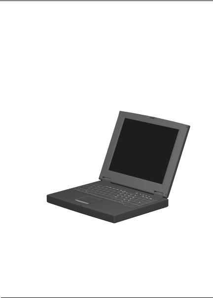
The Compaq Armada 110 and Evo N110 Series notebooks offer advanced modularity, Intel Pentium III or Intel Celeron processors with 64-bit architecture, industry-leading Accelerated Graphics Port (AGP) implementation, and extensive multimedia support.
.
Figure 1–1: Compaq Armada 110 and Evo N110
Maintenance and Service Guide |
1–1 |

Product Description
Models
Computer models are shown in Table1-1.
Table 1-1
Compaq Armada 110 and Evo N110
Models and Model Naming Conventions
Key
N11 |
P |
|
100 |
|
4X |
|
20 |
V |
|
C |
|
128 |
|
98 |
9L |
|
XXXXXX-XXX |
1 |
2 |
|
3 |
|
4 |
|
5 |
6 |
|
7 |
|
8 |
|
9 |
10 |
|
11 |
|
|
|
|
|
|
|
|
|
|
|
|
|
|
|
|
||
Key |
Description |
|
|
|
Options |
|
|
|
|
|
|
||||||
|
|
|
|
|
|
|
|||||||||||
1 |
Brand / Series |
|
A=Armada |
|
11=110 |
||||||||||||
|
designator |
|
|
|
N=Evo |
|
|
|
|
|
|
||||||
|
|
|
|
|
|||||||||||||
2 |
Processor type |
|
P=Intel Pentium III |
C=Intel Celeron |
|||||||||||||
|
|
|
|
|
|
||||||||||||
3 |
Processor speed |
|
100=1.0 GHz |
|
800=800 MHz |
||||||||||||
|
|
|
|
|
|
|
|
850=850 MHz |
|
700=700 MHz |
|||||||
|
|
|
|
|
|
|
|
|
|
||||||||
4 |
Display |
|
|
|
4=14.x” |
|
|
|
X=XGA (1024 × 768) |
||||||||
|
type/size/resolution |
|
2=12.x” |
|
|
|
S=SVGA (800 × 600) |
||||||||||
|
|
|
|
|
|
||||||||||||
5 |
Hard drive size |
|
20=20 GB |
|
10=10.0 GB |
||||||||||||
|
|
|
|
|
|
|
|
15=15 GB |
|
|
|
|
|||||
|
|
|
|
|
|
|
|
||||||||||
6 |
Optical drive |
|
|
|
V=8X Max |
|
D=24X Max CD-ROM |
||||||||||
|
designator |
|
|
|
|
DVD-ROM drive |
|
drive |
|||||||||
|
|
|
|
|
|
|
|
||||||||||
7 |
Integrated |
|
|
|
M=modem |
|
C=modem/NIC |
||||||||||
|
communication |
|
0=none |
|
|
|
|
combination card |
|||||||||
|
|
|
|
|
|
|
|
|
|
||||||||
8 |
RAM |
|
|
|
|
|
64=64 MB |
|
12=128 MB |
||||||||
|
|
|
|
|
|
||||||||||||
9 |
Operating system |
|
8=Windows 98 |
|
8M=Windows 98/ME |
||||||||||||
|
|
|
|
|
|
|
|
Me=Windows |
|
|
dual install |
||||||
|
|
|
|
|
|
|
|
|
|
Millennium |
|
2K=Windows 2000 |
|||||
|
|
|
|
|
|
|
|
|
|
Edition (Me) |
|
|
|
|
|||
|
|
|
|
|
|
|
|
||||||||||
10 |
Battery cells / type |
|
L=9 cells, |
|
|
|
H=9 cells, Nickel |
||||||||||
|
|
|
|
|
|
|
|
|
Lithium ion |
|
|
Metal Hydride |
|||||
|
|
|
|
|
|
|
|
|
|
|
|
|
|
|
|
|
|
11 |
SKU# |
|
|
|
|
|
|
|
|
|
|
|
|
|
|
|
|
|
|
|
|
|
|
|
|
|
|
|
|
|
|
|
|
|
|
1–2 |
Maintenance and Service Guide |

Product Description
Table 1-1
Compaq Armada 110 and Evo N110
Models and Model Naming Conventions (Continued)
1 |
|
2 |
|
3 |
4 |
|
5 |
6 |
7 |
8 |
|
9 |
10 |
11 |
|
|
|
|
|
|
|
|
|
|
|
|
|
|
|
N11 |
|
P |
|
100 |
4X |
|
20 |
V |
C |
25 |
|
2K |
L |
|
|
|
|
|
|
|
|
|
|
|
|
|
|
|
|
Danish |
|
|
|
470028-444 |
Italian |
|
|
470028-462 |
||||||
Dutch |
|
|
|
470028-464 |
Spanish |
|
|
470028-468 |
||||||
European |
|
470028-442 |
Swedish/Finnish |
|
470028-473 |
|||||||||
French |
|
|
|
470028-449 |
Swiss |
|
|
470028-478 & |
||||||
French |
|
|
|
470028-417 |
|
|
|
|
|
470028-483 |
||||
Canadian |
|
|
|
|
|
U.K. English |
|
470028-485 |
||||||
German |
|
470028-454 |
U.S. English |
|
470028-435 |
|||||||||
Greek/Polish |
|
470028-459 |
|
|
|
|
|
|
||||||
|
|
|
|
|
|
|
|
|
|
|
|
|
|
|
N11 |
|
P |
|
100 |
4X |
|
20 |
V |
C |
12 |
|
2K |
L |
|
|
|
|
|
|
|
|
|
|
|
|
|
|
||
Asia/Pacific |
|
470028-515 |
Japanese |
|
|
470028-409 |
||||||||
Australian |
|
470028-489 |
|
|
|
|
|
|
||||||
|
|
|
|
|
|
|
|
|
|
|
|
|
|
|
N11 |
|
P |
|
100 |
4X |
|
20 |
V |
C |
12 |
|
8 |
L |
|
|
|
|
|
|
|
|
|
|
|
|
|
|
||
People’s Republic of China |
|
|
|
|
|
|
|
470028-503 |
||||||
|
|
|
|
|
|
|
|
|
|
|
|
|
|
|
N11 |
|
P |
|
100 |
4X |
|
20 |
V |
C |
12 |
|
M |
L |
|
|
|
|
|
|
|
|
|
|
|
|
|
|
|
|
Arabic |
|
|
|
470028-402 |
Korean |
|
|
470028-420 |
||||||
Czech |
|
|
|
470028-404 |
Norwegian |
|
|
470028-411 |
||||||
Dutch |
|
|
|
470028-409 |
Portuguese |
|
|
470028-412 |
||||||
European |
|
470028-403 |
Russian |
|
|
470028-414 |
||||||||
Greek/Polish |
|
470028-405 |
Slovakian/Slovenian |
470028-416 |
||||||||||
Hebrew |
|
|
|
470028-407 |
Swedish/Finnish |
|
470028-418 |
|||||||
Hong Kong |
|
470028-423 |
Taiwanese |
|
|
470028-421 |
||||||||
Hungarian |
|
470028-406 |
Turkish |
|
|
470028-420 |
||||||||
|
|
|
|
|
|
|
|
|
|
|
|
|
|
|
All Compaq Evo N110 computer models use configuration code KFKZ.
Maintenance and Service Guide |
1–3 |

Product Description
Table 1-1
Compaq Armada 110 and Evo N110
Models and Model Naming Conventions (Continued)
1 |
|
2 |
|
3 |
4 |
5 |
6 |
7 |
|
8 |
|
9 |
10 |
11 |
|
|
|
|
|
|
|
|
|
|
|
|
|
|
|
N11 |
|
C |
|
100 |
4X |
20 |
D |
C |
|
12 |
|
8M |
L |
|
|
|
|
|
|
|
|
|
|
|
|
||||
Asia Pacific/Thai |
470028-598 |
Latin American |
|
470028-441 |
||||||||||
Australian |
|
470028-443 |
|
Spanish |
|
|
|
|||||||
Danish |
|
|
|
470028-428 |
Latin American |
|
470028-497 |
|||||||
French |
|
|
|
470028-429 |
|
Spanish (NAFTA) |
|
|||||||
French |
|
|
|
470028-426 |
Spanish |
|
|
470028-436 |
||||||
Canadian |
|
|
|
|
Swiss |
|
|
470028-438 |
||||||
German |
|
470028-431 |
U.K. English |
|
& 470028-439 |
|||||||||
Italian |
|
|
|
470028-433 |
|
470028-440 |
||||||||
Japanese |
|
470028-445 |
U.S. English |
|
470028-424 |
|||||||||
|
|
|
|
|
|
|
|
U.S. English (NAFTA) |
470028-496 |
|||||
|
|
|
|
|
|
|
|
|
|
|
|
|
|
|
N11 |
|
C |
|
100 |
4X |
20 |
D |
C |
|
12 |
|
2K |
L |
|
|
|
|
|
|
|
|
|
|
|
|
|
|||
Asia Pacific |
|
470028-479 |
Greek/Polish |
|
470028-460 |
|||||||||
Australian |
|
470028-480 |
Italian |
|
|
470028-461 |
||||||||
Danish |
|
|
|
472028-452 |
Japanese |
|
|
470028-482 |
||||||
Dutch |
|
|
|
470028-510 |
Spanish |
|
|
470028-466 |
||||||
European |
|
470028-451 |
Swedish/Finnish |
|
470028-467 |
|||||||||
French |
|
|
|
470028-455 |
Swiss |
|
|
470028-470 & |
||||||
French |
|
|
|
470028-448 |
|
|
|
|
|
|
470028-471 |
|||
Canadian |
|
|
|
|
U.K. English |
|
470028-474 |
|||||||
German |
|
470028-457 |
U.S. English |
|
470028-447 |
|||||||||
|
|
|
|
|
|
|
|
|
|
|
|
|
|
|
All Compaq Evo N110 computer models use configuration code KFKZ.
1–4 |
Maintenance and Service Guide |

Product Description
Table 1-1
Compaq Armada 110 and Evo N110
Models and Model Naming Conventions (Continued)
1 |
2 |
3 |
4 |
5 |
6 |
7 |
8 |
9 |
10 |
11 |
|
|
|
|
|
|
|
|
|
|
|
The following Compaq Armada 110 computer models use |
|
|||||||||
configuration code KFKZ. |
|
|
|
|
|
|
|
|||
|
|
|
|
|
|
|
|
|
|
|
A11 |
P |
850 |
4X |
20 |
D |
C |
64 |
M |
L |
243859-B21 |
|
|
|
|
|
|
|
|
|
|
|
A11 |
P |
850 |
4X |
20 |
D |
C |
64 |
M |
L |
243860-B21 |
|
|
|
|
|
|
|
|
|
|
(NAFTA) |
|
|
|
|
|
|
|
|
|
|
|
A11 |
C |
850 |
4X |
20 |
D |
C |
64 |
M |
H |
258292-B21 |
|
|
|
|
|
|
|
|
|
|
|
A11 |
C |
850 |
4X |
15 |
D |
C |
64 |
M |
H |
243857-B21 |
|
|
|
|
|
|
|
|
|
|
|
A11 |
C |
850 |
4X |
15 |
D |
C |
64 |
M |
H |
243858-B21 |
|
|
|
|
|
|
|
|
|
|
(Europe) |
|
|
|
|
|
|
|
|
|
|
|
A11 |
C |
850 |
2S |
15 |
D |
C |
64 |
M |
H |
243854-B21 |
|
|
|
|
|
|
|
|
|
|
|
A11 |
C |
850 |
2S |
15 |
D |
C |
64 |
M |
H |
243855-B21 |
|
|
|
|
|
|
|
|
|
|
(NAFTA) |
|
|
|
|
|
|
|
|
|
|
|
A11 |
C |
850 |
2S |
15 |
D |
C |
12 |
M |
H |
243856-B21 |
|
|
|
|
|
|
|
|
|
|
|
Maintenance and Service Guide |
1–5 |
Product Description
Table 1-1
Compaq Armada 110 and Evo N110
Models and Model Naming Conventions (Continued)
1 |
2 |
3 |
4 |
5 |
6 |
7 |
8 |
9 |
10 |
11 |
|
|
|
|
|
|
|
|
|
|
|
The following Compaq Armada 110 computer models use |
|
|||||||||
configuration code JMVZ. |
|
|
|
|
|
|
|
|||
|
|
|
|
|
|
|
|
|
|
|
A11 |
P |
800 |
4X |
10 |
V |
C |
64 |
M |
L |
226917-B21 |
|
|
|
|
|
|
|
|
|
|
|
A11 |
P |
800 |
4X |
10 |
D |
C |
64 |
M |
L |
226915-B21 |
|
|
|
|
|
|
|
|
|
|
|
A11 |
P |
800 |
4X |
10 |
D |
C |
64 |
M |
L |
231665-B21 |
|
|
|
|
|
|
|
|
|
|
(NAFTA) |
|
|
|
|
|
|
|
|
|
|
|
A11 |
P |
800 |
2S |
10 |
D |
C |
64 |
M |
L |
226918-B21 |
|
|
|
|
|
|
|
|
|
|
|
A11 |
C |
700 |
4X |
10 |
D |
C |
64 |
M |
L |
231664-B21 |
|
|
|
|
|
|
|
|
|
|
|
A11 |
C |
700 |
4X |
10 |
D |
C |
64 |
M |
H |
226919-B21 |
|
|
|
|
|
|
|
|
|
|
|
A11 |
C |
700 |
2S |
10 |
D |
M |
64 |
8M |
H |
226921-B21 |
|
|
|
|
|
|
|
|
|
|
|
A11 |
C |
700 |
2S |
10 |
D |
M |
64 |
8M |
H |
231663-B21 |
|
|
|
|
|
|
|
|
|
|
(NAFTA) |
|
|
|
|
|
|
|
|
|
|
|
Features
■Processors, varying by computer model:
1.0-GHz or 850or 800-MHz Intel Pentium III processors, with 256-KB integrated cache, varying by computer model
1.0-GHz or 850or 700-MHz Intel Celeron processors, with 128-KB integrated cache, varying by computer model
■ATI RAGE LT Pro, 4-MB SGRAM (synchronous graphics)
■64-MB high-performance Synchronous DRAM (SDRAM), expandable to 320 MB
■Microsoft Windows 98 or Windows Me preinstalled
1–6 |
Maintenance and Service Guide |

Product Description
Displays, varying by computer model:
14.1-inch, SXGA, CTFT (1024 × 768) display, with over
16.8million colors
12.1-inch, SVGA, CTFT (800 × 600) display, with over
16.8million colors
Full-size TouchPad keyboard
Mini PCI 56K V.90 modem or mini PCI V.90 modem plus 10/100 NIC combination card, varying by computer model
One Type II PC Card slot with support for both 32-bit CardBus and 16-bit PC Cards
External AC adapter with power cord
9-cell Lithium ion (Li ion) or Nickel Metal Hydride (NiMH) battery pack
20or 10-GB high-capacity hard drive, varying by computer model
Connectors for:
stereo speaker/headphone
microphone
universal serial bus
RJ-45 network (internal network models only)
RJ-11 modem
keyboard/mouse
AC power
infrared port
Stereo speakers
Maintenance and Service Guide |
1–7 |

Product Description
1.2 Security
If the notebook you are servicing has a password and you know the password, follow these steps to disable or clear the password:
1.Access PhoenixBIOS Setup Utility (PSU) by turning on the computer and pressing F10 when the Compaq logo displays on the screen.
2.Enter the current password and press enter.
3.Move to Password On Boot. Use the + or - key to select disable and press enter.
4.Move to Set Supervisor Password. In the upper space, enter the current password and press enter. In the spaces to enter the new password and confirm new password, press enter. Press enter again to exit the screen.
5.Use the arrow keys to select Exit from the menu bar.
6.Make sure Exit Saving Changes is selected. Press enter, then select Yes to save the changes and exit.
If the notebook you are servicing has an unknown password, follow these steps to clear the password. These steps also clear CMOS.
1.Prepare the computer for disassembly. Refer to Section 5.3, “Preparing the Computer for Disassembly,” for more information.
2.Remove the disk cell RTC battery (refer to Section 5.15, “Disk Cell Real Time Clock (RTC) Battery”).
3.Wait approximately five minutes.
1–8 |
Maintenance and Service Guide |

Product Description
4.Reassemble the computer.
5.Connect AC power to the computer. Do NOT reinsert the battery pack at this time.
6.Turn on the computer.
7.All passwords and all CMOS settings are clear.
1.3Power Management
The computer operating system provides power management utilities that help maintain and conserve power when the computer is running on battery power.
To access power management options, select the power application icon in the operating system’s Control Panel.
Enabling Power Savings
The Enable Power Savings feature in Power Management controls all power management features. When set to disabled, the power menu is automatically disabled. The default setting is enabled.
Timeout Settings
Timeout functions can be set up to power down computer components by selecting the Power Schemes tab from the power application in the operating system’s Control Panel. When a component such as the monitor, hard drive, system, or video is not in use, the component powers down to conserve power. The time out interval can be set from one minute up to several hours. The component will power up again when you access it or press any key.
Maintenance and Service Guide |
1–9 |

Product Description
Setting Standby
Standby is initiated by pressing the Fn+F4 hotkeys or automatically by the computer if it reaches the defined percentage of battery pack power remaining. When Standby is initiated, several subsystems will power off to conserve energy. The system will wake up from Standby when a key is pressed. Although the Standby mode maintains the information and opens the file upon wake-up, any unsaved information is lost if the computer is turned off before ending Standby.
Hibernation
Hibernation is an energy-saving feature and safeguard that saves information in RAM to a hibernation file on the hard drive, then shuts down the computer. Hibernation is initiated by the computer when the computer reaches the defined percentage of battery pack power remaining. To wake the computer from Hibernation, press the power button. When you resume work, the information returns to the screen where you left off.
The computer uses the operating system with a power management utility that helps you maintain and conserve power when the computer is running on battery power.
Standby
Standby is an energy-saving feature that conserves power and reduces startup time.
Standby reduces power to system components that are not being used. Standby can be initiated by you or by the system. When Standby is initiated, all work is saved in random access memory (RAM) and the screen is cleared. When work is resumed, the information returns to the screen.
Refer to Section 1.4 in this chapter to identify the Power, Standby, and Hibernation controls.
1–10 |
Maintenance and Service Guide |
Product Description
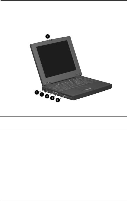
1.4 Computer External Components
The external components on the display and left side of the computer are shown in Figure 1-2 and described in Table 1-2.
Figure 1–2: Display and Left Side Components
Table 1-2
Display and Left Side Components
Item |
Component |
Function |
|
|
|
1 |
Display release latch |
Releases the display to open the computer. |
|
|
|
2 |
Infrared port |
Links another IrDA-compliant device for |
|
|
wireless communication. |
|
|
|
3 |
Vent |
Allows airflow to cool internal components. |
|
|
|
4 |
PC Card slot |
Supports 32-bit (CardBus) and 16-bit |
|
|
PC Cards. |
|
|
|
5 |
PC Card eject button |
Ejects a PC Card from the PC Card slot. |
|
|
|
6 |
Diskette drive |
Accepts 3.5-inch diskettes. |
|
|
|
Maintenance and Service Guide |
1–11 |
Product Description
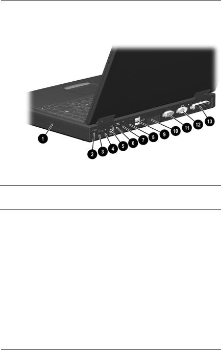
The computer right side and rear panel components are shown in Figure 1-3 and described in Table 1-3.
Figure 1–3: Right Side and Rear Panel Components
Table 1-3
Right Side and Rear Panel Components
Item |
Component |
Function |
|
|
|
1 |
Optical drive |
Accepts CDor DVD-ROM disks, |
|
|
depending on the computer model. |
|
|
|
2 |
Security cable slot |
Attaches an optional security cable to the |
|
|
computer. |
|
|
|
3 |
Stereo speaker/ |
Connects stereo speakers, headphones, |
|
headphone jack |
headset, or television audio. |
|
|
|
4 |
Microphone jack |
Connects a single sound channel |
|
|
microphone. |
|
|
|
1–12 |
Maintenance and Service Guide |

Product Description
Table 1-3
Right Side and Rear Panel Components (Continued)
Item |
Component |
Function |
|
|
|
|
|
5 |
Keyboard/mouse |
Connects an optional full-sized keyboard or |
|
|
connector |
a mouse. When this connector is used, both |
|
|
|
the external and computer keyboard and |
|
|
|
pointing device are active. An optional |
|
|
|
splitter/adapter allows both an external |
|
|
|
keyboard and mouse to be used at the |
|
|
|
same time. |
|
|
|
|
|
6 |
Power jack |
Connects any one of the following: |
|
|
|
■ |
AC Adapter |
|
|
■ |
Optional Automobile Power |
|
|
|
Adapter/Charger |
|
|
■ Optional Aircraft Power Adapter |
|
|
|
|
|
7 |
RJ-11 jack (internal |
Connects the modem cable to an internal |
|
|
modem models only) |
modem. |
|
|
|
A modem cable is included with |
|
|
|
|
internal modem models. |
|
|
|
|
8 |
RJ-45 jack |
Connects the network cable. |
|
|
(network models only) |
A network cable is included with |
|
|
|
|
network models. |
|
|
|
|
9 |
Universal Serial Bus |
Connects USB devices. |
|
|
(USB) connector |
|
|
|
|
|
|
10 |
Vent |
Allows airflow to cool internal components. |
|
|
|
|
|
11 |
Serial connector |
Connects a serial device. |
|
|
|
|
|
12 |
External monitor |
Connects an external monitor or overhead |
|
|
connector |
projector. |
|
|
|
|
|
13 |
Parallel connector |
Connects a parallel device. |
|
|
|
|
|
Maintenance and Service Guide |
1–13 |
Product Description
The computer keyboard components are shown in Figure 1-4 and described in Table 1-4.
Figure 1–4: Keyboard Components
1–14 |
Maintenance and Service Guide |

Product Description
|
|
Table 1-4 |
|
Keyboard Components |
|
|
|
|
Item |
Component |
Function |
|
|
|
1 |
Fn key |
Used with hotkeys to perform preset hotkey |
|
|
functions. |
|
|
|
2 |
Caps lock key |
Turns on the caps lock function. |
|
|
|
3 |
F1 through F12 |
Perform preset functions. |
|
function keys |
|
|
|
|
4 |
Display switch |
Turns off the computer display if the |
|
|
computer is closed while on. |
|
|
|
5 |
Embedded numeric |
Converts keys to numeric keypad. |
|
keypad |
|
|
|
|
6 |
Cursor control keys |
Move the cursor around the screen. |
|
|
|
7 |
Windows |
Displays a menu when using a Microsoft |
|
application keys |
application. The menu is the same that is |
|
|
displayed by pressing the right mouse |
|
|
button. |
|
|
|
8 |
Microsoft logo key |
Displays Windows Start menu. |
|
|
|
Maintenance and Service Guide |
1–15 |
Product Description
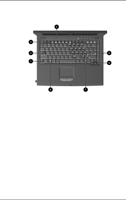
The components on the top of the computer are shown in Figure 1-5 and described in Table 1-5.
Figure 1–5: Top Components
|
|
Table 1-5 |
|
|
Top Components |
|
|
|
Item |
Component |
Function |
|
|
|
1 |
Speakers (2) |
Produce stereo sound. |
|
|
|
2 |
Hard drive light |
On: The primary hard drive is being |
|
|
accessed. |
|
|
|
1–16 |
Maintenance and Service Guide |

Product Description
|
|
Table 1-5 |
|
Top Components (Continued) |
|
|
|
|
Item |
Component |
Function |
|
|
|
3 |
Battery light |
Green steady: Battery charging is complete. |
|
|
Red steady: Battery pack is charging. |
|
|
Red blinking: Battery pack is being queried, |
|
|
computer cannot communicate with battery |
|
|
pack, or battery pack is bad. |
|
|
|
4 |
Num lock light |
On: Num lock is on and the embedded |
|
|
numeric keypad is enabled. |
|
|
|
5 |
Caps lock light |
On: Caps lock is on. |
|
|
|
6 |
Scroll lock light |
On: Scroll lock is on. |
|
|
|
7 |
Power button |
Turns the computer on or off or exits |
|
|
Standby. |
|
|
|
8 |
Easy Access buttons (4) |
Four buttons that provide quick access to |
|
|
the Internet. |
|
|
|
9 |
Microphone |
Inputs single-channel sound to the |
|
|
computer; can be used whether the |
|
|
computer is open or closed. |
|
|
|
10 |
Right TouchPad button |
Functions like the right mouse button on an |
|
|
external mouse. |
|
|
|
11 |
TouchPad |
Moves the mouse cursor, selects, and |
|
|
activates. |
|
|
|
12 |
Left TouchPad button |
Functions like the left mouse button on an |
|
|
external mouse. |
|
|
|
Maintenance and Service Guide |
1–17 |
Product Description
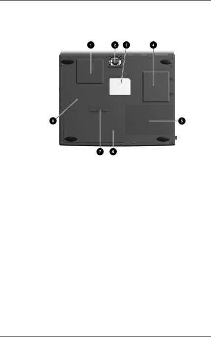
The external components on the bottom of the computer are shown in Figure 1-6 and described in Table 1-6.
Figure 1–6: Bottom Components
1–18 |
Maintenance and Service Guide |

Product Description
Table 1-6
Bottom Components
Item |
Component |
Function |
|
|
|
1 |
Mini PCI slot cover |
Contains the mini PCI modem or |
|
|
network interface card. |
|
|
|
2 |
Fan vent |
Provides airflow to cool internal |
|
|
components. |
|
|
|
3 |
Certificate of Authenticity label |
Contains the Product Key, which |
|
|
may need to be entered before |
|
|
using some Windows operating |
|
|
systems. |
|
|
|
4 |
Memory expansion |
Covers the memory expansion |
|
compartment |
compartment. |
|
|
|
5 |
Front label area |
Contains agency information. |
|
|
|
6 |
Battery compartment |
Accepts a 9-cell Lithium ion (Li ion) |
|
|
or Nickel Metal Hydride (Ni MH) |
|
|
battery pack. |
|
|
|
7 |
Battery release latch |
Releases the battery pack from |
|
|
the battery bay. |
|
|
|
8 |
Serial number |
Identifies the computer. |
|
|
|
Maintenance and Service Guide |
1–19 |

Product Description
1.4 Design Overview
This section presents a design overview of key parts and features of the computer. Refer to Chapter 3, “Illustrated Parts Catalog” and Chapter 5, “Removal and Replacement Procedures.”
The system board provides the following device connections:
■Memory expansion board
■Hard drive
■Display
■Keyboard/TouchPad
■Audio
■Intel Pentium III or Intel Celeron Processors
■Fan
■PC Card
■Modem or modem/NIC
■Microphone
The computer uses an electrical fan for ventilation. The fan is controlled by a temperature sensor and is designed to turn on automatically when high temperature conditions exist. These conditions are affected by high external temperatures, system power consumption, power management/battery conservation configurations, battery fast charging, and software applications. Exhaust air is displaced through the ventilation grill located on the right side of the computer.
ÄCAUTION: To properly ventilate the computer, allow at least a 3-inch (7.6 cm) clearance on the left and right sides of the computer.
1–20 |
Maintenance and Service Guide |

2
Troubleshooting
ÅWARNING: Only authorized technicians trained by Compaq should repair this equipment. All troubleshooting and repair procedures are detailed to allow only subassembly/module level repair. Because of the complexity of the individual boards and subassemblies, no one should attempt to make repairs at the component level or to make modifications to any printed wiring board. Improper repairs can create a safety hazard. Any indication of component replacement or printed wiring board modification may void any warranty or exchange allowances.
Utilities that are preinstalled on the computer include:
■PhoenixBIOS Setup Utility—Allows you to modify or restore factory default settings and configure the system BIOS to diagnose and solve minor problems.
■Power Management—Allows you to reduce your computer power consumption. Power Management information is contained in Chapter 1.
■Security—Allows you to set or remove your power-on password. Security information is contained in Chapter 1.
Maintenance and Service Guide |
2–1 |

Troubleshooting
Using the PhoenixBIOS Setup Utility
The PhoenixBIOS Setup Utility (PSU) is built into the system. You can configure the system BIOS and modify or restore factory default settings, such as date and time, types of disk drives, power management, and password settings. To run PSU, press F10 during system startup. When the main screen displays, use the keyboard and arrow keys to move around the menus and make selections.
2–2 |
Maintenance and Service Guide |

Troubleshooting
Troubleshooting Flowcharts for
Portable Computers
|
Table 2-1 |
|
Troubleshooting Flowcharts Overview |
|
|
Section |
Description |
|
|
2.1 |
Initial troubleshooting |
|
|
2.2 |
No power, part 1 |
|
|
2.3 |
No power, part 2 |
|
|
2.4 |
No power, part 3 |
|
|
2.5 |
No power, part 4 |
|
|
2.6 |
No video, part 1 |
|
|
2.7 |
No video, part 2 |
|
|
2.8 |
Non-functioning docking station |
|
|
2.9 |
No operating system (OS) loading |
|
|
2.10 |
No OS loading from hard drive, part 1 |
|
|
2.11 |
No OS loading from hard drive, part 2 |
|
|
2.12 |
No OS loading from hard drive, part 3 |
|
|
2.13 |
No OS loading from diskette drive |
|
|
2.14 |
No OS loading from CD-/DVD-ROM drive |
|
|
2.15 |
No audio, part 1 |
|
|
2.16 |
No audio, part 2 |
|
|
2.17 |
Non-functioning device |
|
|
2.18 |
Non-functioning keyboard |
|
|
2.19 |
Non-functioning pointing device |
|
|
2.20 |
No network or modem connection |
|
|
Maintenance and Service Guide |
2–3 |

Troubleshooting
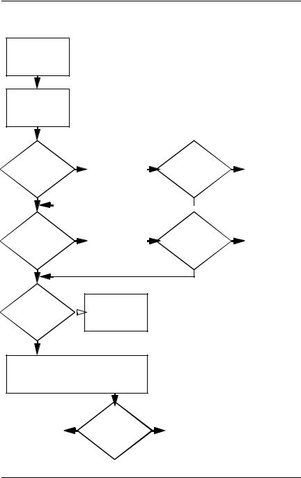
2.1 Initial Troubleshooting
Begin
Troubleshooting.
N
Is there |
Go to |
|
Section 2.2, |
||
power? |
||
No Power. |
||
|
Y
N
Beeps, |
|
Check |
|
|
|
|
LED board, |
|
|
|
|
LEDs, or error |
|
|
|
|
|
|
speaker |
|
|
|
|
Messages? |
|
|
|
|
|
|
connections. |
|
|
|
|
Y |
|
All drives |
|||
|
|
||||
|
|
||||
|
|
|
working? |
||
|
N |
|
Y |
||
Is there video? |
|
Go to |
|
|
|
|
|
|
|
||
|
Section 2.6, |
|
|
|
|
(no boot) |
|
No Video. |
|
|
|
Y |
|
|
Keyboard/ |
||
|
|
pointing |
|||
|
|
|
device |
||
|
N |
|
working? |
||
|
|
Y |
|||
Is the OS |
|
Go to |
|||
|
|
|
|
||
|
Section 2.9, |
|
|
|
|
loading? |
|
|
|
|
|
|
No OS Loading. |
|
|
|
|
|
|
|
|
|
|
Y |
|
|
Connecting |
||
|
|
||||
|
|
|
to network |
||
|
N |
|
or modem? |
||
|
|
Y |
|||
|
|
|
|||
Is there |
|
Go to |
|||
|
Section 2.15, |
||||
sound? |
|
||||
|
No Audio. |
||||
|
|
||||
|
|
|
End |
||
Y
N
Go to Section 2.17,  Non-Functioning Device.
N |
Go to |
|
Section 2.18, |
|
Non Functioning |
|
Keyboard, |
|
or Section 2.19, |
|
Non-Functioning |
|
Pointing Device. |
N
Go to Section 2.20,
Network or Modem Connection.
2–4 |
Maintenance and Service Guide |
Troubleshooting
2.2 No Power, Part 1
No Power
(Power LED
is off).
Remove from docking station if applicable.
|
|
N |
|
|
N |
||
Power up |
|
*Reset |
Power up |
|
Go to |
||
|
|
Section 2.3, |
|||||
on battery |
|
on battery |
|
||||
|
power. |
|
No Power, |
||||
power? |
|
power? |
|
||||
|
|
|
Part 2. |
||||
Y |
|
|
Y |
|
|||
|
|
|
|
||||
|
|
|
|
||||
|
|
|
|
|
|
||
|
|
N |
|
|
N |
||
Power up |
|
*Reset |
Power up |
|
Go to |
||
|
|
Section 2.4, |
|||||
on AC |
|
on |
AC |
|
|||
|
power. |
|
No Power, |
||||
power? |
|
power? |
|
||||
|
|
|
Part 3. |
||||
Y |
|
|
Y |
|
|||
|
|
|
|
||||
|
|
|
|
||||
Y
Power up
in docking  Done station?
N
1.Reseat power cables in docking station and at the AC outlet.
2.Ensure AC power source is active.
3.Ensure power strip is working.
*Note:
1.On some models, there is a separate reset button.
2.On some models, the computer may be reset using the Standby switch and either the lid switch or the main power switch.
|
Y |
|
N |
|
|
|
Power up |
|
Go to |
Done |
|
|
Section 2.8, |
|
|
in docking |
|
||
|
|
station? |
|
Non-Functioning |
|
|
|
Docking Station. |
|
|
|
|
|
|
Maintenance and Service Guide |
2–5 |
Loading...