

MODEL-1701 COLOUR VIDEO MONITOR USER'S MANUAL

BEZIRKSREGIERUNG BRAUNSCHWEIG
Bauartzulassung Nds 601/83
Aufgrund von § 7 ff der Verordnung über den Schutz vor Schäden durch Röntgenstrahlen (Röntgenverordnung – RöV) vom 01. 03. 73 (BGBl. I S. 173) wird nach Prüfung durch die Physikalisch-Technische Bundesanstalt (Prüfungsschein Nr. 6.62–S 157 vom 25. 04. 83 auf Antrag der
Firma COMMODORE Büromaschinen GmbH, Frankfurt/M. vertreten durch COMMODORE Büromaschinen GmbH Werk Braunschweig Ernst-Amme-Str. 24–25 3300 Braunschweig
die Bauart folgenden Störstrahlers zugelassen:
| Gegenstand: | Video-Monitor |
|---|---|
| Firmenbezeichnung: | Commodore Video Monitor Modell 1701 |
| Bildröhre: |
Hitachi
Type: 370 FVB 22 |
| Betriebsbedingungen: |
Hochspannung: max. 24 kV
Strahlstrom: 1,0 mA |
| Hersteller: |
Victor Company of Japan, Ltd.
1106, Heta, Iwai-shi, Ibaraki-ken, Japan 306–06 |
| Unterlagen zur | |
| Bauart-Prüfung: |
Schaltplan Nr. CS 10,96 vom 03. 03. 1983
Bedienungsanleitung Nr. 1701-IB vom 03. 03. 1983 |
| Bauartzeichen: | Nds 601/83 |
Befristung der Bauartzulassung
Die Bauartzulassung gilt für die ihr entsprechenden Störstrahler, die bis zum
30.06.93
in den Verkehr gebracht worden sind.
Braunschweig, den 30.06.83 -204.22.93.27.Co-
C. Sato
C. Sato
Bezirksregierung Braunschweig Im Auftrage
45-1
Krüwel
CAUTION
In case of technical problems, especially if your set produces only sound with no picture, or if the viewing area shrinks to half size, unplug the set and call your dealer or service technician.
For your safety, please refer to "SAFETY PRECAUTIONS" on pages 14 and 15 in this user's manual.
Incorrect servicing, especially of the high-voltage circuitry, and replacing the picture tube with one of a different type can increase the emission of X-rays. Any units modified in such a way no longer conform to regulations and should not be used.
ACHTUNG
Bei technischen Problemen, insbesondere wenn der Monitor nur Ton und kein Bild produziert oder wenn das sichtbare Bild auf die halbe Größe schrumpft, ziehen Sie das Netzkabel aus der Steckdose und wenden sich an Ihren Händler oder Kundendienst.
Bitte lesen Sie die "SICHERHEITSHINWEISE" auf den SEITEN 15 bis 17 dieser Bedienungsanleitung.
Unsachgemäße Eingriffe, insbesondere das Verändern der Hochspannung-Schaltung oder das Auswechseln der Bildröhre gegen eine eines anderen Typs, können dazu führen, daß Röntgenstrahlung in erheblicher Stärke auftritt. Ein so verändertes Gerät entspricht nicht mehr den Bestimmungen und darf infolgedessen nicht betrieben werden.
INSTRUCTIONS/ZUR BEACHTUNG
- Before attempting to operate this product, be sure that you have carefully read this manual.
- Do not open or attempt to service this product.
- Vor der Inbetriebnahme dieses Geräts diese Bedienungsanleitung sorgfältig durchlesen.
- Dieses Gerät nicht öffnen oder Wartungsarbeiten durchführen.
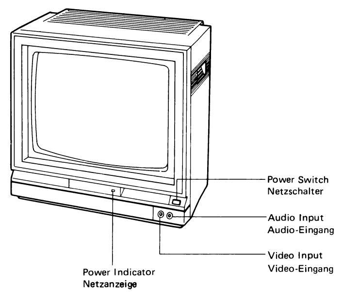
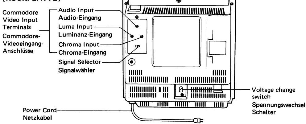
NAMES OF SECTIONS/BEZEICHNUNGEN DER TEILE
[FRONT SCREEN] [VORDERSEITE]
[FRONT CONTROL SECTION] [VORDERES BEDIENFELD]
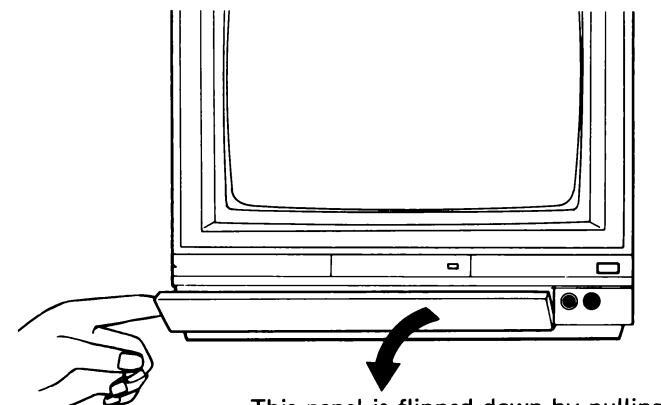
This panel is flipped down by pulling it towards you as shown in the diagram.
Diese Blende kann durch Ziehen nach vorne heruntergeklappt werden.
CONNECTION/ANSCHLÜSSE
In order to connect this video monitor to a Commodore personal computer, use the connection cable (monitor cable). When connecting them, turn off power of the personal computer and the video monitor first.
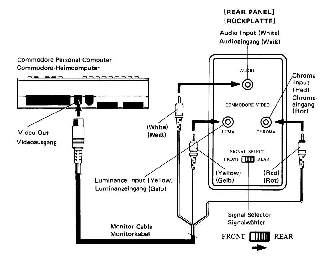
(1) How to use the Commodore video input (on the rear side)
If your personal computer has the Commodore video output terminal, connect it to the exclusive Commodore video input terminal. The use of this terminal allows the display of a picture with better resolution that the ordinary connection described in (2). Connect the DIN connector of the monitor cable to the Commodore video output terminal of the personal computer and connect RCA pin plugs of the monitor cable to the rear terminals of the monitor as follows: audio output plug (white) to AUDIO IN (white), luminance output plug (yellow) to LUMA IN (yellow) and chroma output plug (red) to CHROMA IN (red), and then place the SIGNAL SELECTOR SWITCH to its "REAR" position.
Zum Anschließen dieses Videomonitors an einen Commodore-Heimcomputer das Verbindungskabel (Monitorkabel) verwenden. Vor dem Anschließen den Heimcomputer und den Videomonitor ausschalten.
(1) Verwendung des Commodore-Videoeingangs (an der Rückseite)
Wenn Ihr Heimcomputer mit einem Commodore-Videoausgang-Anschluß ausgestattet ist, diesen Ausgang mit dem Commodore-Videoeingang-Anschluß des Monitors verbinden. Die Verwendung dieses Anschlusses ermöglicht ein Bild mit besserer Auflösung als der normale Anschluß, der unter (2) beschrieben ist. Den DIN-Stecker des Monitorkabels an den Commodore-Videoausgang-Anschluß des Heimcomputers anschließen und die RCA-Stiftstecker des Monitorkabels wie folgt an die Anschlüsse an der Rückseite des Monitors anschließen: Audioausgang-Stecker (weiß) an AUDIO IN (weiß), Luminanzausgang-Stecker (gelb) an LUMA IN (gelb) un Chromaausgang-Stecker (rot) an CHROMA IN (rot), danach den SIGNAL SELECT-Schalter auf "REAR" stellen.
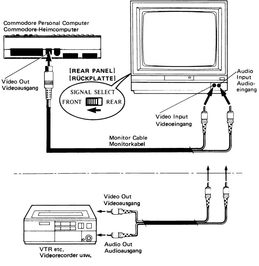
(2) How to use video input and audio input jacks (on the front panel)
Connect the ordinary composite output signal terminals of the personal computer or the output of the video camera, VTR or TV tuner, etc. to the VIDEO IN and AUDIO IN jacks on the front panel, and set the SIGNAL SELECTOR SWITCH on the rear panel to its "FRONT" position.
The 1701 can now be used as an ordinary video monitor.
(2) Verwendung des Videoeingangs und der Audioeingang-Buchsen (an der Frontplatte)
Den normalen FBAS-Ausgang eines Heimcomputers, einer Videocamera, eines Videorecorders, eines Fernsehtuners usw. an die VIDEO IN- und AUDIO IN-Buchsen an der Frontplatte anschließen und den SIGNAL SELECT-Schalter an der Rückplatte auf "FRONT" stellen, Dann kann der 1701 als normaler Videomonitor verwendet werden.
TURNING POWER ON/SPANNUNGSVERSORGUNG
- AC power connection- (Only for 240 V version model)
- Anschluß des Netzkabels (nur für 240 V-Version)
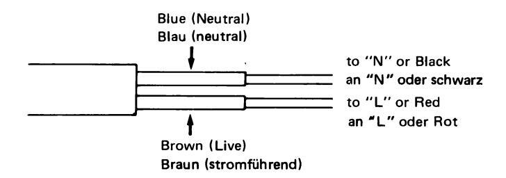
IMPORTANT
The wires in this mains lead are coloured in accordance with the following code: Blue: Neutral Brown: Live
As the colours of the wires in the mains lead of this apparatus may not correspond with the coloured markings identifying the terminals in your plug proceed as follows.
The wire which is coloured blue must be connected to the terminal which is marked with the letter N or coloured black.
The wire which is coloured brown must be connected to the terminal which is marked with the letter L or coloured red.
NOTE
The rating plate is on the rear of the unit.
WICHTIG
Die Litzen des Netzkabels sind wie folgt farbig gekennzeichnet:
Blau: Neutral Braun: Stromführend
Wenn die Farben der Litzen des Netzkabels dieses Geräts nicht mit den Farbmarkierungen an den Anschlußklemmen des Steckers übereinstimmen, den Anschluß wie folgt durchführen:
Die blaue Litze an die Anschlußklemme anschließen, die mit dem Buchstaben N oder der Farbe Schwarz markiert ist.
Die braune Litze an die Anschlußklemme anschließen, die mit dem Buchstaben L oder der Farbe Rot markiert ist.
HINWEIS
Die Leistungsplatte befindet sich an der Rückseite des Geräts.
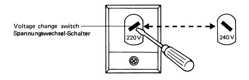
The PAL version 1701 video monitor comes in different versions for power supply voltages of 220 V. (West Germany) and 240 V (England). Be sure to check that your set corresponds with your local power supply voltage before use. The specifications are indicated clearly on the box. If you need to change the input power voltage of your 1701, turn the VOLTAGE
CHANGE SWITCH by screw driver and select correct voltage.
Die PAL-Version des 1701 Videomonitors wird f ür die Netzspannungen 220 V (Bundesrepublik Deutschland) und 240 V (Gro ßbritannien) geliefert.
Vor dem Anschließen überprüfen, daß der Monitor der örtlichen Netzspannung entspricht. Diese Angabe ist auf dem Verpackungskarton aufgedruckt.
Die Spannung des 1701 kann mit dem Spannungswechsel-Schalter mit einem Schraubenzieher umgestellt werden.
Then turn on the power of the video monitor.
POWER SWITCH
[PUSH] ( - ON) INDICATOR lamp will light indicating that the power is on.
[PUSH AGAIN] ( _ OFF) The power will be cut off.
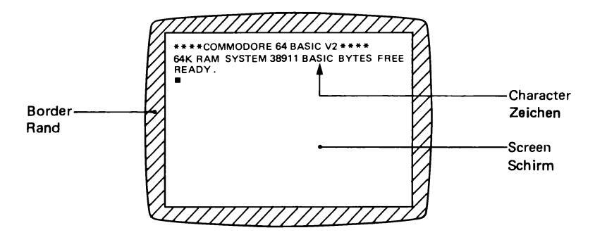
Next, turn on the power of the Commodore personal computer. At this point, if the screen of the monitor is as shown below, it means that both the computer and the monitor are operating correctly.
Different computers have different displays on the monitor screen. Refer to the user's manual of the computer.
Erst jetzt den Videomonitor einschalten.
NETZSCHALTER
Der Monitor wird durch Drücken (,----) des Netzschalters eingeschaltet, die Anzeige leuchtet.
Der Monitor wird durch nochmaliges Drücken ( ...................................
Danach den Commodore-Heimcomputer einschalten. Wenn jetzt auf dem Monitorschirm die folgende Anzeige erscheint, arbeiten sowohl der Monitor als auch der Computer ordnungsgemäß.
Die Anzeige auf dem Monitorschirm ist abhängig vom verwendeten Computer. Beziehen Sie sich auf die Bedienungsanleitung des Computers.
In the case of a Commodore 64 personal computer Bei Verwendung des Commodore-Heimcomputers 64
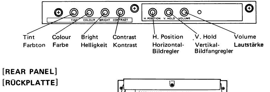
MANUAL CONTROLS/REGLER
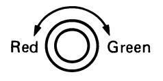
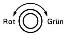
• Tint Control
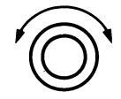
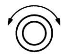
Colour Control
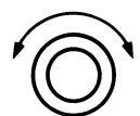
Brightness Control
Contrast Control
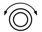
• H. Position Control
• V. Hold Control
Volume Control
Turn to the left to add more red colour and to the right to add more green colour.
(Try to adjust by focusing the human complexion to be viewed as natural as possible. The normal setting for this knob is at the centre, click-stop position.)
Turn to the left for pale colours and to the right for more vivid colours. (The normal setting for this knob is at the centre, click-stop position.)
Turn to the right to brighten the picture. (The normal setting for this knob is at the centre, click-stop position.)
Turn to the right to increase contrast. (The normal setting for this knob is at the centre, click-stop position.)
Turn to the right to move the centre of the picture to the right and to the left to move it to left.
Turn this knob to stop vertical rolling of the picture.
Turn this knob to the right to increase sound volume, and to the left to decrease volume.
• Farbton-Regler (TINT)
• Farb-Regler (COLOUR)

Helligkeits-Regler (BRIGHT)
• Kontrast-Regler (CONTRAST)
Horizontal-Bildregler (H. POSITION)
• Vertikal-Bildfangreger (V. HOLD)
Lautstärke-Regler (VOLUME)
Durch Drehen dieses Reglers nach links wird das Bild rötlicher und durch Drehen nach rechts grünlicher.
(Die beste Einstellung ist erzielt, wernn die menschliche Hautfarbe normal erscheint. Die normale Einstellung dieses Reglers ist die Einrastposition in der Mitte.)
Durch Drehen des Reglers nach links wird das Bild blasser und durch Drehen nach rechts lebendiger. (Die normale Einstellung dieses Reglers ist die Einrastposition in der Mitte.)
Durch Drehen des Reglers nach rechts wird das Bild heller. (Die normale Einstellung dieses Reglers ist die Einrastposition in der Mitte.)
Durch Drehen dieses Reglers nach rechts wird der Kontrast verstärkt. (Die normale Einstellung dieses Reglers ist die Einrastposition in der Mitte.)
Durch Drehen dieses Reglers nach rechts bewegt sich die Mitte des Bildes nach rechts und durch Drehen nach links bewegt sich die Mitte des Bildes nach links.
Diesen Regler drehen, um ein wanderndes Bild zu stoppen.
Durch Drehen dieses Reglers nach rechts wird die Lautstärke erhöht und durch Drehen nach links vermindert.
SPECIFICATIONS/TECHNISCHE DATEN
| Туре | : Colour video monitor |
|---|---|
| Colour system | : PAL |
| Power requirements | : AC 220 V, 50 Hz or AC 240 V, 50 Hz |
| Power consumption | : 80 W |
| Screen size | : 14″ (33 cm) |
| 90° deflection angle. Vertical stripe. 0.64 pitch | |
| Audio output | : 1.2 W |
| Speaker | : 10 cm round x 1 |
| External input terminals | |
| Video input | |
| Input type | : Composite video signal (CVBS) |
| Input level | : 1.0 Vp-p (sync negative 0.3 V) |
| Input impedance | : 75 Ω |
| Connector type | : RCA pin jack |
| Commodore video input | |
| 1) Luminance signal input | |
| Input type | : Composite video signal (VS) |
| Input level | : 1.0 Vp-p (sync negative 0.3 V) |
| Input impedance | : 75 Ω |
| Connector type | : RCA pin jack |
| 2) Chrominance signal input | |
| Input type | : PAL chroma signal |
| Input level | : 1.0 Vp-р |
| Input impedance | : 75 Ω |
| Connector type | : RCA pin jack |
| Audio input | |
| Input level | : 1.0 Vp-p |
| Input impedance | : 10 kΩ |
| Connector type | : RCA pin jack |
| Dimensions | : 373(W) x 363(H) x 409(D) mm |
| Weight | : Unit weight; 14.6 kg |
| Gross weight; 16.3 kg |
Design and specifications subject to change without notice.
| Тур | : Farbvideomonitor |
|---|---|
| Farbsystem | : PAL |
| Spannungsversorgung | : Netz 220 V, 50 Hz oder Netz 240 V, 50 Hz |
| Leistungsaufnahme | : 80 W |
| Bildschirmgröße | : 14" (33 cm), 90° Ablenkwinkel, |
| - | Vertikalstreifen 0,64 mm Teilung |
| Audioausgang | : 1,2 W |
| Lautsprecher | : 10 cm rund x 1 |
| Eingangsanschlüsse | |
| Videoeingang | |
| Eingangtyp | : FBAS |
| Eingangpegel | : 1,0 Vs-s (negative Synchronisation 0,3 V) |
| Eingangsimpedanz | : 75 Ohm |
| Commodore-Videoeingang | |
| 1) Luminanzsignal-Eingang | |
| Eingangtyp | : BAS |
| Eingangpegel | : 1,0 Vs-s (negative Synchronisation 0,3 V) |
| Eingangsimpedanz | : 75 Ohm |
| Buchsentyp | : RCA-Stiftbuchse |
| 2) Chrominanzsignal-Eingang | |
| Eingangtyp | : PAL-Chromasignal |
| Eingangpegel | : 1,0 Vs-s |
| Eingangsimpedanz | : 75 Ohm |
| Buchsentyp | : RCA-Stiftbuchse |
| Audioeingang | |
| Eingangpegel | : 1,0 Vs-s |
| Eingangsimpedanz | : 10 kOhm |
| Buchsentyp | : RCA-Stiftbuchse |
| Abmessungen | : 373(B) x 363(H) x 409(T) mm |
| Gewicht | : Gewicht des Geräts: 14,6 kg |
| Bruttogewicht: 16,3 kg |
Technische Änderungen vorbehalten.
SAFETY PRECAUTIONS/SICHERHEITSHINWEISE
Electrical energy can perform many useful functions. This unit has been engineered and manufactured to assure your personal safety. But improper use can result in potential electrical shock or fire hazards . In order not to defeat the safeguards incorporated in this monitor, observe the following basic rules for its installation, use and servicing.
And also follow all warnings and instructions marked on your video monitor.
INSTALLATION
- 1. Operate the set only from a power source as indicated on the set or refer to the user's manual for this information. If you are not sure of the type of power supply to your home, consult your dealer or local power company.
- Overloaded AC outlets and extension cords are dangerous, and so are frayed power cords and broken plugs. They may result in a shock or fire hazard. Call your service technician for replacement.
- 3. Do not allow anything to rest on or roll over the power cord, and do not place the set where power cord is subject to traffic or abuse. This may result in a shock or fire hazard.
- Do not use this set near water -- for example, near a bathtub, washbowl, kitchen sink, or laundry tub, in a wet basement, or near a swimming pool, etc.
-
Sets are provided with ventilation openings in the cabinet to allow heat generated during operation to be released. If these openings are blocked, heat built-up within the set can cause failures which may result in a fire hazard. Therefore:
- Never block the bottom ventilation slots by placing it on a bed, sofa, rug, etc.;
- Never block the bottom ventuation sides by placing it on a bed, sola, rug, etc., Never place a set in a "built-in" enclosure unless proper ventilation is provided;
- Never cover the openings with cloth or other material;
- Never place the set near or over a radiator or heat register.
-
6. To avoid personal injury:
- Do not place a set on a sloping shelf unless properly secured;
- Use only a cart or stand recommended by the manufacturer;
- Do not try to roll a cart with small casters across thresholds or deep pile carpets.
- Wall and shelf mounted installations should use factory approved mounting instructions.
USE
- 7. Always turn the set off if it is necessary to leave the room for more than a short period of time. Never leave a set on when leaving the house. A possible malfunction may result in a fire hazard.
- 8. Caution children about dropping or pushing objects into the set's cabinet openings. Some internal parts carry hazardous voltages and contact can result in a fire or electrical shock.
- 9. Unplug the set from the wall outlet before cleaning the face of the picture tube. Use a slightly damp (not wet) cloth. Do not use an aerosol directly on the picture tube since it may overspray and cause electrical shock.
- Never add accessories to a set that has not been designed for this purpose. Such additions may result in a shock hazard.
- For added protection of the set during a lightning storm or when the set is to be left unattended for an extended period of time, unplug it from the wall outlet. This will prevent possible shock and fire hazards due to lightning storms or power line surges.
- 12. Do not bring magnetic devices such as magnets or motors near the picture tube. These things have a bad effect on the color purity of the picture.
13. Sometimes you may feel static electricity when you touch the surface of the picture tube.
However, this is normal for any TV set and is harmless to the human body.
SERVICE
-
14. Unplug this set from the wall outlet and refer servicing to qualified service personnel under the following conditions:
- A. When the power cord or plug is damaged or frayed.
- B. If liquid has been spilled into the set.
- C. If the set has been exposed to rain or water.
- D. If the set does not operate normally by following the operating instructions. Adjust only those controls that are covered in the operating instructions as improper adjustment of other controls may result in damage and will often require extensive work by a qualified technician to restore the set to normal operation.
- E. If the set has been dropped or the cabinet has been damaged.
- F. When the set exhibits a distinct change in performance -- this indicates a need for servicing.
- G. If snapping or popping from the set is continuous or frequent while the set is operating. It is normal for some sets to make occasional snapping or popping sounds, particularly when being turned on or off.
- 15. Do not attempt to service this set yourself as opening or removing covers may expose you to dangerous voltage or other hazards. Refer all servicing to qualified service personnel.
- 16. When replacement parts are required, have the service technician verify in writing that the replacements he uses have the same safety characteristics as the original parts. Use of manufacturer's specified replacements can prevent fire, shock, or other hazards.
- 17. Upon completion of any service or repairs to the set, please ask the service technician to perform the safety check described in the manufacturers' service literature.
- When a video monitor reaches the end of its useful life, improper disposal could result in a picture tube implosion. Ask a qualified service technician to dispose of the set.
Elektrische Energie dient vielen nutzlichen Zwecken. Beim Bau Ihres Videomonitor wurde auf größte Sicherheit geachtet, eine unsachgemäße Bedienung kann jedoch Kurzschlüsse auslösen, die zu Bränden führen oder elektrische Beschädigungen zur Folge haben. Damit Sicherungen und Schutzvorrichtungen des Geräts nicht beschädigt werden, sind bei Aufstellung, Betrieb und Reparatur folgende Vorschriften einzuhalten.
Beachten Sie auch alle Warnungen und Hinweise, die auf Ihrem Videomonitor angegeben sind.
AUFSTELLUNG
- Das Gerät darf nur von einer zulässigen Spannungsquelle betrieben werden. Siehe die Kennzeichnungsplakette auf dem Gerät oder seine Bedienungsanleitung. Wenn Sie Zweifel bezüglich der Spannungsversorgung in Ihrem Haushalt haben, wenden Sie sich bitte an Ihren Händler oder an Ihre Elektrizitätsgesellschaft. Beziehen Sie sich für batteriebetriebene Geräte auf die Bedienungsanleitung.
- Überlastete Netzanschlüsse und Verlängerungskabel stellen eire Gefahr dar, ebenso wie Kabel mit schadhafter Isolierung und zerbrochenen Steckern. Solche Beschädigungen können zu Kurzschlüssen oder Bränden führen. Beauftragen Sie mit der Ersetzung durch neue Teile Ihren Kundendienst.
- 3. Stellen Sie keine Gegenstände auf das Kabel und lassen Sie auch keinen Wagen darüberrollen. Stellen Sie den Videomonitor nicht an Orten auf, an denen viel hin- und hergegangen wird oder wo die Gefahr besteht, daß er falsch bedient wird, da dies zu einer Beschädigung führen könnte.
- 4. Verwenden Sie diesen Videomonitor nicht in der Nähe von Wasser zum Beispiel neben einer Badewanne, einem Waschbecken, einem Küchenabfluß, in einem feuchten Raum oder neben einem Swimmingpool usw.
-
Im Gehäuse des Videomonitors befinden sich Belüftungslöcher, durch welche die Hitze entweichen kann, die sich während des Betriebs entwickelt. Wenn diese blockiert werden, kann die Stauung der Hitze im Geräteinnern einen Brand auslösen. Deshalb:
- Die Belüftungsschlitze auf dem Boden eines tragbaren Videomonitors dürfen nicht blockiert werden, wenn das Gerät auf ein Bett, Sofa, einen Teppich etc. gestellt wird.
- In ein Einbaufach darf der Videomonitor nur gestellt werden, wenn f ür eine ausreichende Bel üftung gesorgt ist.
- Die Belüftungslöcher dürfen nicht mit einem Tuch oder mit einer Decke bedeckt werden.
- Stellen Sie das Gerät niemals neben oder auf einen Heizkörper.
-
6. Zum Schutz gegen Verletzungen ist zu beachten:
- Das Gerät darf nur auf schräge Wandbretter gestellt werden, wenn es entsprechend befestigt und gesichert ist.
- Verwenden Sie für die Aufstellung des Geräts nur Radgestelle, die vom Gerätehersteller dafür empfohlen werden.
- Schieben Sie ein Gestell oder einen Wagen mit kleinen R\u00e4dern nicht \u00fcber T\u00fcrschwellen oder wulstige Teppiche.
- Wandbretter und Regale, auf die das Gerät gestellt werden soll, müssen den Instruktionen des Herstellers gemäß an der Wand befestigt sein.
GEBRAUCH
- 7. Wenn Sie den Raum für längere Zeit verlassen, sollte der Videomonitor ausgeschaltet werden. Wenn Sie aus dem Haus gehen, sollte das Gerät unbedingt ausgeschaltet werden, da eine mögliche Betriebsstörung in Ihrer Abwesenheit u.U. einen Brand auslösen kann.
- 8. Kinder sollten darauf hingewiesen werden, daß es gefährlich ist, Gegenstände durch die Öffnungen im Gehäuse ins Geräteinnere zu werfen. Einige interne Einzelteile weisen gefährliche Spannungen auf und ein Kontakt kann einen Kurzschluß auslösen.
- 9. Vor der Reinigung des Bildschirms sollte das Netzkabel aus der Steckdose gezogen werden. Verwenden Sie zur Reinigung ein feuchtes (nicht nasses) Tuch. Benutzen Sie keine Reinigungsflüssigkeit aus Sprühdosen, da diese, wenn sie ins Geräteinnere eindringen sollte, zu Kurzschlüssen führen könnte.
- 10. Schließen Sie niemals andere Geräte an Ihren Videomonitor an, wenn dieser für solche Anschlüsse nicht eingerichtet ist, da sonst Kurzschlüsse ausgelöst werden können.
- 11. Bei längerer Abwesenheit und zwecks besserem Schutz gegen Gewitterauswirkungen sollte der Anschluß zum Netz und die Antennenleitung unterbrochen werden. Dadurch werden mögliche elektrische Beschädigungen durch Gewitter oder Netzspannungsstöße ausgeschlossen.
- 12. Keine magnetischen Geräte wie starke Magnete oder Motoren in die Nähe der Bildröhre bringen, weil dadurch die Farbreinheit des Bildes beeinträchtigt wird.
13. Manchmal kann sich beim Berühren der Bildröhre statische Elektrizität bemerkbar machen.
Dies ist jedoch normal bei jedem Fernseher und nicht gefährlich für den menschlichen Körper.
WARTUNG
-
14. In den folgenden Fällen das Netzkabel aus der Steckdose ziehen und den Videomonitor von einem qualifizierten Kundendienst-Techniker warten lassen:
- A. Wenn das Netzkabel oder der Stecker beschädigt oder zerbrochen ist.
- B. Wenn Flussigkeit in den Videomonitor eingedrungen ist.
- C. Wenn der Videomonitor Regen oder Wasser ausgesetzt war.
- D. Wenn der Videomonitor unter Befolgung der Bedienungsanleitung nicht normal arbeitet. Stellen Sie nur die in der Bedienungsanleitung angegebenen Bedienelemente ein, da durch Verstellen anderer Regler Beschädigungen verursacht werden können, deren Behebung oft erheblichen Aufwand erfordert.
- E. Wenn der Videomonitor fallengelassen wurde oder das Gehäuse beschädigt ist.
- F. Wenn die Leistung des Videomonitors nachläßt dies weist darauf hin, daß Servicearbeiten erforderlich sind.
- G. Wenn bei laufendem Gerät ununterbrochenes Knistern oder andere Geräusche auftreten.
Gelegentliches Knistern oder andere Geräusche, vor allem beim Ein- und Auschalten, haben nichts zu bedeuten.
- 15. Versuchen Sie nicht, Ihren Videomonitor selbst zu reparieren, da nach dem Öffnen des Gehäuses gefährliche Spannungen zugänglich sind. Überlassen Sie alle Wartungsarbeiten qualifiziertem Servicepersonal.
- 16. Achten Sie darauf, daß der Kundendienst beim Einbau von Ersatzteilen nur solche verwendet, die dieselben Sicherheitsvorrichtungen bestizen wie die ausgewechselten Teile und den allgemeinen Vorschriften entsprechen. Die Verwendung von vom Hersteller empfohlenen Ersatzteilen hilft Brände, Kurzschlüsse und andere Störungen zu verhüten.
- Nach jeder Wartung oder Reparatur sollten Sie den Kundendienst bitten, den in den Wartungsplänen des Herstellers vorgeschriebenen Sicherheitskontrolltest durchzuführen.
- 18. Wenn ein Videomonitor ausgedient hat und beiseite geschafft wird, ist bei seiner Vernichtung darauf zu achten, daß bei seiner Bildröhre keine Implosion auftritt. Beauftragen Sie mit dem Abtransport den Kundendienst oder einen zuständigen Fachmann.


Printed in Japan 1701-PAL-IB-B


 Loading...