


 Loading...
EN
TECHNICAL MANUAL
Technical manual for Ikall external unit Art. 4681 and power supply unit Art. 1210

Warning
•Install the equipment by carefully following the instructions given by the manufacturer and in compliance with the standards in force.
•All the equipment must only be used for the purpose it was designed for. Comelit Group S.p.A. does not assume responsibility for improper use of the apparatus, for modifications made by third parties for any reason or purpose, or for the use of non-original accessories and materials.
•All the products comply with the requirements of the 2014/30/EU and 2014/35/EU directives. This is proved by the CE mark on the products themselves.
•Do not route the riser wires in proximity to power supply cables (230/400V).
•Installation, mounting and assistance procedures for electrical devices must only be performed by specialised electricians.
•Disconnect the power supply before carrying out any maintenance operations.
•The camera must not be installed opposite bright light sources, or in places where the filmed subject is against the light.
•In poor light conditions, cameras with colour sensors are less sensitive than black and white cameras. We therefore recommend, in dimly lit environments, to install an additional light source.
• Connect the module support frame to earth (see Fig.)
Table of contents |
|
Warning......................................................................................................... |
2 |
Table of contents......................................................................................... |
2 |
Description................................................................................................... |
3 |
External unit installation............................................................................. |
4 |
Installation information........................................................................................ |
5 |
Button programming.................................................................................. |
6 |
Dip switch programming table.................................................................. |
7 |
EXAMPLE: dip switch setting for code 200...................................................... |
8 |
Special programmes................................................................................... |
9 |
Power supply unit Art. 1210..................................................................... |
12 |
Consumption management..................................................................... |
13 |
External unit module consumption table........................................................ |
13 |
Operating distances with Art. 1210........................................................ |
14 |
Distances valid for articles: 6700W, 6701W, 6701B, 6721W, 6801W........... |
14 |
Distances valid for Art. 6601W.......................................................................... |
15 |
Maximum system expansion............................................................................ |
15 |
Wiring diagrams......................................................................................... |
16 |
Video entry phone system with 1 external unit Art. 4681: system |
|
commissioning/voltage test with system at rest........................................... |
16 |
Wiring diagram for system with external unit 4681 |
|
and supplementary power supply unit Art. 1595 |
|
(for maximum number of expansion modules).............................................. |
17 |
Wiring diagram for system with digital call module Art. 3360B.................. |
18 |
Wiring diagram for system with external unit Art. 300(1-12)XVB................ |
18 |
Wiring diagram for system with electronic digital key module Art. 3348B19 |
|
Wiring diagram for system with electronic digital key module Art. 3348B |
|
and supplementary power supply unit Art. 1595 (for maximum number of |
|
expansion modules)............................................................................................ |
20 |
Wiring diagram for system with single-plate entrance panel Art. 3063D..21 |
|
Wiring diagram for system with single-plate entrance panel Art. 3063D |
|
with supplementary power supply unit Art. 1595 (for maximum number of |
|
expansion modules)............................................................................................ |
22 |
Wiring diagram for system with Vandalcom entrance panel and |
|
conventional button modules Art. 3064S........................................................ |
23 |
Wiring diagram for systems with Vandalcom entrance panel and |
|
conventional button modules Art. 3064S and supplementary power supply |
|
unit Art. 1595 (for maximum number of expansion modules)..................... |
24 |
Wiring diagram for systems with digital call modules Art. 3070S and |
|
Art.3072S............................................................................................................... |
25 |
Wiring diagram for systems with Vandalcom electronic key module Art. |
|
3188S..................................................................................................................... |
26 |
Wiring diagram for systems with Art. SK9015 for connection of readers Art. |
|
SK9000I and Art. SK9001I.................................................................................. |
27 |
Use of external unit relay on lock release or actuator command............... |
28 |
Use of RC network for lock filter on relay contacts...................................... |
28 |
Wiring diagram with safety lock....................................................................... |
28 |
Wiring diagrams for system with switching device Art. 1404............ |
29 |
System with Art. 1210: switching device in STANDARD |
|
mode and 2 inputs.............................................................................................. |
29 |
System with Art. 1210: switching device in STANDARD |
|
mode, 1 main input and 2 secondary inputs.................................................. |
30 |
System with Art. 1210: switching devices in STANDARD |
|
mode and 8461 KIT in cascade........................................................................ |
32 |
System with Art. 1210: switching devices in STANDARD |
|
mode, branched 8461 KIT.................................................................................. |
34 |
Wiring digram for systems with camera module Art. 1409................ |
35 |
System Art. 1210: remote camera module Art. 1409 in generic |
|
actuator mode..................................................................................................... |
35 |
2

Description |
|
1. |
|
DIP |
ON |
PR |
J11 CNF J9 |
ON |
|
OFF |
|
2. |
3. |
4. |
5. |
6. |
7. |
8. |
9. |
1. S1 DIP switches for function programming and setting the user code.
2. PR switch for input/output programming.
3. J11 jumper for power supply management. Remove in case of power on V+ and V-. J9 jumper for power supply management. Remove in case of power on V+ and V-.
4. CNF switch for confirming special programmes.
5. CAUTION: connector reserved for the module 1621VC.
6. Loudspeaker volume control.
7. 8-pole cable connector.
8. JP1 RC network management for door lock filter on relay contacts (see page 28).
9. Terminal block for connection:
SE+ SEelectric lock connection
COM common relay contact
NC normally closed relay contact
NO normally open relay contact
GND input reference negative for DO-RTE
DO door opened signal input
RTE local lock release input
V- power supply negative
V+ power supply positive
LL bus line connection
3
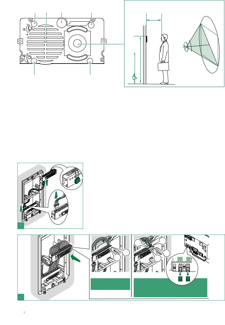
1. |
2. |
3. |
4. |
42,5 cm
5.
100°
cm |
163 cm |
130 |
|
7. |
6. |
1. Signalling LED: call sent.
2. Speaker.
3. Microphone.
4. Signalling LED: system busy.
5. Colour camera.
6. Signalling LED: sound activated.
7. Signalling LED: lock release activated.
External unit installation
1 |
|
|
|
-V |
+L |
|
|
|
|
+L |
|
|
|
PR J11CNF J9 |
A powered by |
B powered by |
|
Art. 1210 |
power supply |
|
2 |
Art. 1595 |
|
|
|
|
4 |
|
|

If the total power consumption of the modules exceeds 100mA then it will be necessary to use the power supply unit Art. 1595.
To calculate the power consumption values see “Consumption management” on page 13.
1 |
1 |
2 |
3 |
WHITE |
OFF |
BLUE |
|
|
LED |
|
|
O |
|
|
F |
|
|
F |
|
|
Nameplate LED lighting |
|
|
selection. |
3
2
4
5
1


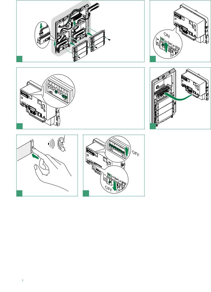
Speaker adjustment
4
Alternative microphone position (excluding 4 module entrance panel)
1 |
|
|
360° |
|
open |
3 |
2 |
5 close |
|
Installation information
•The module Art. 4681 operates by default as a main external unit (timed busy signal). To set it as a secondary external unit (busy signal active for the whole time the riser is in use), set all the selector DIP switches to ON.
•When a call is transmitted from the external unit, if a busy tone is heard instead of the ringtone, this means communication with another external unit is in progress.
Art. 4681 must only be used while powered by Art. 1210.
5
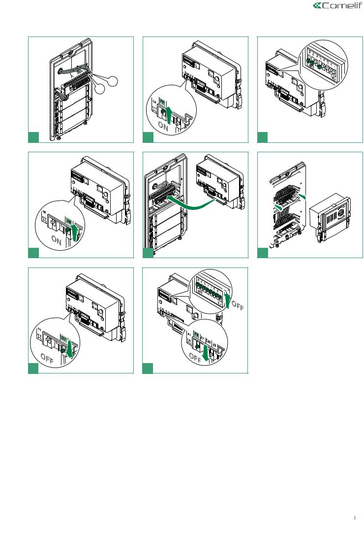
Button programming
|
33433 |
|
33434 |
1 |
33436 |
Set the user code using the dip switches; see the table on page 7.
3 |
|
|
1 |
|
2 |
5 |
6 |
2 |
4 |
6

Dip switch programming table
Code |
Dip switch ON |
Name |
Code |
Dip switch ON |
Name |
Code |
Dip switch ON |
Name |
|
|
|
|
|
|
|
|
|
1 |
1 |
|
50 |
2,5,6 |
|
99 |
1,2,6,7 |
|
2 |
2 |
|
51 |
1,2,5,6 |
|
100 |
3,6,7 |
|
3 |
1.2 |
|
52 |
3,5,6 |
|
101 |
1,3,6,7 |
|
4 |
3 |
|
53 |
1,3,5,6 |
|
102 |
2,3,6,7 |
|
5 |
1.3 |
|
54 |
2,3,5,6 |
|
103 |
1,2,3,6,7 |
|
6 |
2.3 |
|
55 |
1,2,3,5,6 |
|
104 |
4,6,7 |
|
7 |
1,2,3 |
|
56 |
4,5,6 |
|
105 |
1,4,6,7 |
|
8 |
4 |
|
57 |
1,4,5,6 |
|
106 |
2,4,6,7 |
|
9 |
1.4 |
|
58 |
2,4,5,6 |
|
107 |
1,2,4,6,7 |
|
10 |
2.4 |
|
59 |
1,2,4,5,6 |
|
108 |
3,4,6,7 |
|
11 |
1,2,4 |
|
60 |
3,4,5,6 |
|
109 |
1,3,4,6,7 |
|
12 |
3.4 |
|
61 |
1,3,4,5,6 |
|
110 |
2,3,4,6,7 |
|
13 |
1,3,4 |
|
62 |
2,3,4,5,6 |
|
111 |
1,2,3,4,6.7 |
|
14 |
2,3,4 |
|
63 |
1,2,3,4,5.6 |
|
112 |
5.67 |
|
15 |
1,2,3,4 |
|
64 |
7 |
|
113 |
1,5,6,7 |
|
16 |
5 |
|
65 |
1.7 |
|
114 |
2,5,6,7 |
|
17 |
1.5 |
|
66 |
2.7 |
|
115 |
1,2,5,6,7 |
|
18 |
2.5 |
|
67 |
1,2,7 |
|
116 |
3,5,6,7 |
|
19 |
1,2,5 |
|
68 |
3.7 |
|
117 |
1,3,5,6,7 |
|
20 |
3.5 |
|
69 |
1,3,7 |
|
118 |
2,3,5,6,7 |
|
21 |
1,3,5 |
|
70 |
2,3,7 |
|
119 |
1,2,3,5,6.7 |
|
22 |
2,3,5 |
|
71 |
1,2,3,7 |
|
120 |
4,5,6,7 |
|
23 |
1,2,3,5 |
|
72 |
4.7 |
|
121 |
1,4,5,6,7 |
|
24 |
4.5 |
|
73 |
1,4,7 |
|
122 |
2,4,5,6,7 |
|
25 |
1,4,5 |
|
74 |
2,4,7 |
|
123 |
1,2,4,5,6.7 |
|
26 |
2,4,5 |
|
75 |
1,2,4,7 |
|
124 |
3,4,5,6,7 |
|
27 |
1,2,4,5 |
|
76 |
3,4,7 |
|
125 |
1,3,4,5,6.7 |
|
28 |
3,4,5 |
|
77 |
1,3,4,7 |
|
126 |
2,3,4,5,6.7 |
|
29 |
1,3,4,5 |
|
78 |
2,3,4,7 |
|
127 |
1,2,3,4,5,6,7 |
|
30 |
2,3,4,5 |
|
79 |
1,2,3,4,7 |
|
128 |
8 |
|
31 |
1,2,3,4,5 |
|
80 |
5.7 |
|
129 |
1.8 |
|
32 |
6 |
|
81 |
1,5,7 |
|
130 |
2.8 |
|
33 |
1.6 |
|
82 |
2,5,7 |
|
131 |
1,2,8 |
|
34 |
2.6 |
|
83 |
1,2,5,7 |
|
132 |
3.8 |
|
35 |
1,2,6 |
|
84 |
3,5,7 |
|
133 |
1,3,8 |
|
36 |
3.6 |
|
85 |
1,3,5,7 |
|
134 |
2,3,8 |
|
37 |
1,3,6 |
|
86 |
2,3,5,7 |
|
135 |
1,2,3,8 |
|
38 |
2,3,6 |
|
87 |
1,2,3,5,7 |
|
136 |
4.8 |
|
39 |
1,2,3,6 |
|
88 |
4,5,7 |
|
137 |
1,4,8 |
|
40 |
4.6 |
|
89 |
1,4,5,7 |
|
138 |
2,4,8 |
|
41 |
1,4,6 |
|
90 |
2,4,5,7 |
|
139 |
1,2,4,8 |
|
42 |
2,4,6 |
|
91 |
1,2,4,5,7 |
|
140 |
3,4,8 |
|
43 |
1,2,4,6 |
|
92 |
3,4,5,7 |
|
141 |
1,3,4,8 |
|
44 |
3,4,6 |
|
93 |
1,3,4,5,7 |
|
142 |
2,3,4,8 |
|
45 |
1,3,4,6 |
|
94 |
2,3,4,5,7 |
|
143 |
1,2,3,4,8 |
|
46 |
2,3,4,6 |
|
95 |
1,2,3,4,5.7 |
|
144 |
5.8 |
|
47 |
1,2,3,4,6 |
|
96 |
6.7 |
|
145 |
1,5,8 |
|
48 |
5.6 |
|
97 |
1,6,7 |
|
146 |
2,5,8 |
|
49 |
1,5,6 |
|
98 |
2,6,7 |
|
147 |
1,2,5,8 |
|
|
|
|
|
|
|
|
|
|
7

Code |
Dip switch ON |
Name |
Code |
Dip switch ON |
Name |
Code |
Dip switch ON |
Name |
|
|
|
|
|
|
|
|
|
148 |
3,5,8 |
|
179 |
1,2,5,6,8 |
|
210 |
2,5,7,8 |
|
149 |
1,3,5,8 |
|
180 |
3,5,6,8 |
|
211 |
1,2,5,7,8 |
|
150 |
2,3,5,8 |
|
181 |
1,3,5,6,8 |
|
212 |
3,5,7,8 |
|
151 |
1,2,3,5,8 |
|
182 |
2,3,5,6,8 |
|
213 |
1,3,5,7,8 |
|
152 |
4,5,8 |
|
183 |
1,2,3,5,6.8 |
|
214 |
2,3,5,7,8 |
|
153 |
1,4,5,8 |
|
184 |
4,5,6,8 |
|
215 |
1,2,3,5,7.8 |
|
154 |
2,4,5,8 |
|
185 |
1,4,5,6,8 |
|
216 |
4,5,7,8 |
|
155 |
1,2,4,5,8 |
|
186 |
2,4,5,6,8 |
|
217 |
1,4,5,7,8 |
|
156 |
3,4,5,8 |
|
187 |
1,2,4,5,6.8 |
|
218 |
2,4,5,7,8 |
|
157 |
1,3,4,5,8 |
|
188 |
3,4,5,6,8 |
|
219 |
1,2,4,5,7.8 |
|
158 |
2,3,4,5,8 |
|
189 |
1,3,4,5,6.8 |
|
220 |
3,4,5,7,8 |
|
159 |
1,2,3,4,5.8 |
|
190 |
2,3,4,5,6.8 |
|
221 |
1,3,4,5,7.8 |
|
160 |
6.8 |
|
191 |
1,2,3,4,5,6,8 |
|
222 |
2,3,4,5,7.8 |
|
161 |
1,6,8 |
|
192 |
7.8 |
|
223 |
1,2,3,4,5,7,8 |
|
162 |
2,6,8 |
|
193 |
1,7,8 |
|
224 |
6,7,8 |
|
163 |
1,2,6,8 |
|
194 |
2,7,8 |
|
225 |
1,6,7,8 |
|
164 |
3,6,8 |
|
195 |
1,2,7,8 |
|
226 |
2,6,7,8 |
|
165 |
1,3,6,8 |
|
196 |
3,7,8 |
|
227 |
1,2,6,7,8 |
|
166 |
2,3,6,8 |
|
197 |
1,3,7,8 |
|
228 |
3,6,7,8 |
|
167 |
1,2,3,6,8 |
|
198 |
2,3,7,8 |
|
229 |
1,3,6,7,8 |
|
168 |
4,6,8 |
|
199 |
1,2,3,7,8 |
|
230 |
2,3,6,7,8 |
|
169 |
1,4,6,8 |
|
200 |
4,7,8 |
|
231 |
1,2,3,6,7.8 |
|
170 |
2,4,6,8 |
|
201 |
1,4,7,8 |
|
232 |
4,6,7,8 |
|
171 |
1,2,4,6,8 |
|
202 |
2,4,7,8 |
|
233 |
1,4,6,7,8 |
|
172 |
3,4,6,8 |
|
203 |
1,2,4,7,8 |
|
234 |
2,4,6,7,8 |
|
173 |
1,3,4,6,8 |
|
204 |
3,4,7,8 |
|
235 |
1,2,4,6,7.8 |
|
174 |
2,3,4,6,8 |
|
205 |
1,3,4,7,8 |
|
236 |
3,4,6,7,8 |
|
175 |
1,2,3,4,6.8 |
|
206 |
2,3,4,7,8 |
|
237 |
1,3,4,6,7.8 |
|
176 |
5,6,8 |
|
207 |
1,2,3,4,7.8 |
|
238 |
2,3,4,6,7.8 |
|
177 |
1,5,6,8 |
|
208 |
5,7,8 |
|
239 |
1,2,3,4,6,7,8 |
|
178 |
2,5,6,8 |
|
209 |
1,5,7,8 |
|
*240 |
5,6,7,8 |
|
|
|
|
|
|
|
|
|
|
*NOTE: code 240 is reserved for the porter switchboard
EXAMPLE: dip switch setting for code 200
8
Special programmes
L
1 |
4 |
7 |
2 |
5 |
1 |
2 |
8 |
Set the dip switches for the function you wish to program, see
3 the table on page 10.
6 |
9

CODE |
DIP SWITCHES ON |
FUNCTIONS |
|
|
|
|
|
|
|
De-misting heating element |
|
|
|
|
|
213 |
1,3,5,7,8 |
OFF (default) |
|
|
|
|
|
212 |
3,5,7,8 |
ON |
|
|
|
|
|
|
|
|
|
|
|
Audio-visal messages |
|
|
|
|
|
195 |
1,2,7,8 |
Hebrew |
|
|
|
|
|
196 |
3,7,8 |
Polish |
|
|
|
|
|
197 |
1,3,7,8 |
Catalan |
|
|
|
|
|
198 |
2,3,7,8 |
Galician |
|
|
|
|
|
199 |
1,2,3,7,8 |
Basque |
|
|
|
|
|
206 |
2,3,4,7,8 |
Danish |
|
|
|
|
|
207 |
1,2,3,4,7.8 |
Norwegian |
|
|
|
|
|
211 |
1,2,5,7,8 |
Swedish |
|
|
|
|
|
215 |
1,2,3,5,7.8 |
Italian |
|
|
|
|
|
216 |
4,5,7,8 |
French |
|
|
|
|
|
217 |
1,4,5,7,8 |
Spanish |
|
|
|
|
|
218 |
2,4,5,7,8 |
Dutch |
|
|
|
|
|
219 |
1,2,4,5,7.8 |
Greek |
|
|
|
|
|
220 |
3,4,5,7,8 |
English |
|
|
|
|
|
221 |
1,3,4,5,7.8 |
German |
|
|
|
|
|
222 |
2,3,4,5,7.8 |
Portuguese |
|
|
|
|
|
|
|
|
|
202 |
2,4,7,8 |
Enables voice message (door opened warning) when the RTE contact is closed |
|
|
|
|
|
203 |
1,2,4,7,8 |
Disables voice message (door opened warning) when the RTE contact is closed (default |
|
setting) |
|||
|
|
||
|
|
|
|
208 |
5,7,8 |
Enables “awaiting reset time" on lock release command. |
|
|
|
|
|
209 |
1,5,7,8 |
Disables “awaiting reset time" on lock release command (awaiting response time or talk |
|
time will be activated). |
|||
|
|
||
|
|
|
|
210 |
2,5,7,8 |
visual messages only |
|
|
|
|
|
214 |
2,3,5,7,8 |
OFF (default) |
|
|
|
|
|
|
|
|
|
|
|
Actuator command management |
|
|
|
N.B. Art. 1256 in generic actuator mode must not be present in the system. |
|
|
|
|
|
227 |
1,2,6,7,8 |
Actuator function on S serial line = enabled |
|
|
|
|
|
228 |
3,6,7,8 |
Actuator function on S serial line = disabled (default) |
2291,3,6,7,8 Enabling C.NC.NO relay on actuator command: 2 secs.
2302,3,6,7,8 Enabling C.NC.NO relay on actuator command: 4 secs.
2311,2,3,6,7.8 Enabling C.NC.NO relay on actuator command: 8 secs.
Door lock
2451,3,5,6,7.8 Door lock time: 2 secs. + disabling tone (default)
2462,3,5,6,7.8 Door lock time: 4 secs.
2471,2,3,5,6,7,8 Door lock time: 8 secs.
2484,5,6,7,8 Door lock confirmation tone: enabled
2511,2,4,5,6,7,8 Relay C.NC.NO in parallel to SE (default)
2523,4,5,6,7.8 Lock-release always enabled (default)
2531,3,4,5,6,7,8 Lock-release only enabled for user called
|
|
System functions |
|
|
|
232 |
4,6,7,8 |
Awaiting response time: 60 secs.. (default) |
2331,4,6,7,8 Awaiting response time: 120 secs.
2342,4,6,7,8 Awaiting response time: 30 secs.
10
235 |
1,2,4,6,7.8 |
Talk time: 90 secs. (default) |
|
|
|
236 |
3,4,6,7,8 |
Talk time: 180 secs. |
2371,3,4,6,7.8 Self-ignition: enabled (default)
2382,3,4,6,7.8 Self-ignition: disabled
2391,2,3,4,6,7,8 Confirmation tone on user call = enabled (default)
240 |
5,6,7,8 |
Confirmation tone on user call = disabled |
|
|
|
|
|
|
243 |
1,2,5,6,7.8 |
Awaiting reset time: 10 secs. (default) |
|
|
|
244 |
3,5,6,7,8 |
Awaiting reset time: 1 sec. |
|
|
|
|
|
|
208 |
5,7,8 |
Reset after lock-release in audio: enabled (default) |
|
|
|
209 |
1,5,7,8 |
Reset after lock-release in audio: disabled |
2491,4,5,6,7.8 Call transmission: single (default)
2502,4,5,6,7.8 Call transmission: triple
|
|
System mode |
|
|
|
0 |
|
Simplebus (default) |
|
|
|
255 |
1,2,3,4,5,6,7.8 |
Simplebus Top (NO Art. 4680KC) |
|
|
|
|
|
|
254 |
2,3,4,5,6,7,8 |
Restore default |
11
Loading...