


 Loading...
www.cobra.com
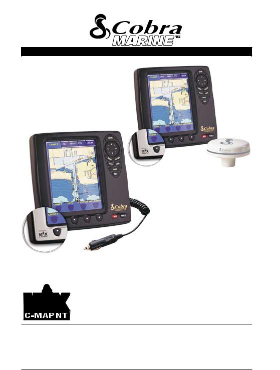
MC 600Cx and MC 600Cx EU
MC 600Ci and MC 600Ci EU

 Owner’s Manual
All rights reserved. No part of this publication may be reproduced or distributed in any form or by any means, or stored in a database or retrieval system, without prior written permission of the publisher.
©2006 Cobra Electronics CorporationTM |
©2006 Cobra ® Electronics Europe Limited |
6500 West Cortland Street, Chicago |
Dungar House, Northumberland Avenue, Dun Laoghaire |
Illinois 60707 USA |
County Dublin, Ireland |
Cobra®, NightWatch®, Nothing Comes Close to a Cobra® and the snake design are registered trademarks of Cobra Electronics Corpor a- tion, USA.
Cobra Electronics CorporationTM, CobraMarineTM and iASAPTM are trademarks of Cobra Electronics Corporation, USA. C-MAPTM, C-MAP Navigation Technology, C-MAP NT MAX TM and C-MAP NT+ TM are registered trademarks of C-MAP S.r.l.
(S3igCO7vc/S3egCO7vc-a1000-251105)
Our Thanks to You and
Customer Assistance
Thank you for purchasing a CobraMarineTM MC 600Ci or MC 600Cx chartplotter.
Properly used, this product will give you many years of reliable service.
How Your Cobra® Chartplotter Works
The CobraMarineTM chartplotter is a state-of-the-art computerized electronic chart system, designed as a sophisticated navigation aid. User friendly operations make the chartplotter easy to operate. All calculations and information necessary for the navigation are performed and displayed on the screen quickly and accurately providing all of the capabilities of a conventional GPS but with the added benefit of a powerful electronic chart display. The cartographic information is obtained from C-MAPTM C-CARDs (cartography data cards) that are available through your local dealer. For additional information on C-MAPTM Cartography visit web site at www.c-map.com.
CUSTOMER ASSISTANCE INFORMATION
Should you encounter any problems with this product, or not understand its many features, please refer to this Owner’s Manual. If you require further assistance after reading this Owner’s Manual, Cobra Electronics CorporationTM offers the following customer assistance services:
For Assistance in the U.S.A
Automated Help Desk English only.
24 hours a day, 7 days a week 773-889-3087 (phone).
Customer Assistance Operators English and Spanish.
8:00 a.m. to 6:00 p.m. through Fri. (excepth holidays) 773-889-3087 (phone).
Questions English and Spanish.
Faxes can be received at 773-622-2269 (fax).
Technical Assistance
English only: www.cobra.com (on-line: Frequently Asked Questions). English and Spanish: productinfo@cobra.com (e-mail).
For Assistance Outside the U.S.A
Contact Your Local Dealer or Distributor. Please see www.cobra.com for contact information.
A1 |
Owner's Manual |
Nothing Comes Close to a Cobra® |
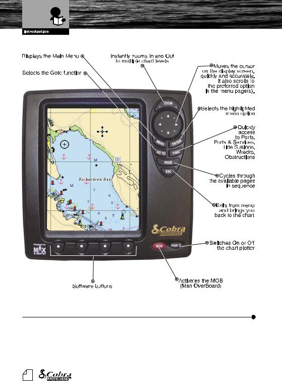
Control and Indicators
SOFTWARE BUTTONS FUNCTIONALITY
The software buttons have different functions according to the modes of operation: their labels for the current functions, are shown on the screen right above the buttons. They can also be used like FM radio preset buttons to save quick access to your favorite pages.
When pressing the ESC button the four software button, labels disappear.
A2 |
Owner's Manual |
Nothing Comes Close to a Cobra® |
Software Features and
Technical Specifications
SOFTWARE FEATURES
Detailed Base Map Included
3D Mapping (view charts in either top down or new 3D perspective modes) 12 Channel WAAS GPS with iASAPTM
Sunlight and NightWatchTM Modes
Easy surfing among the available pages (Data, Highway, Sun & Moon, Split, GPS Status, System and Welcome pages)
Fish Finder and Combo pages (available with Fish Finder device connected)
DSC Calling integration
1000 Waypoints and 50 Routes (50 Waypoints/Route) Create, Move, Insert, Edit or Erase Waypoint
Create, Save, Name, Edit or Follow a Route Navigation to Goto
Route Data Report and User Points (Marks/Waypoints) List pages Find Ports Services, Ports, Tide Stations, Wrecks, Obstructions, Coordinates and User Points
Display Tide Info and Tide Graph page
Automatic Info on cartographic objects and User Points Display vessel's position, direction and Track
10 Tracks with 16 Color Options
Alarms Handling (Anchor Drag, Arrival, Off Course, Proximity, Depth, Etc.) Man OverBoard (MOB) to navigate back to a missing person or object Demo Modes
TECHNICAL SECIFICATIONS
|
|
Power Consumption |
: |
10 - 35 V |
|
|
|||
|
|
|||
|
|
Interface |
: |
NMEA-0183 |
|
|
|||
|
|
|||
|
|
Autopilot Interface |
: |
NMEA-0180, NMEA-0180/CDX, NMEA-0183 |
|
|
|||
|
|
|||
|
|
Display |
: |
6” Color TFT with Anti-Reflective Coating (Active Area 5.7”) |
|
|
|||
|
|
|||
|
|
Display Resolution |
: |
240 x 320 pixels |
|
|
|||
|
|
|||
|
|
Cartography |
: C-MAP NT MAXTM or C-MAP NT+TM C-CARDs |
|
|
|
|||
|
|
|||
|
|
Operating Range |
: 0/+55 degree Celsius |
|
|
|
|||
|
|
|||
|
|
Water Proof Specification : Submersible to IPX7 or JIS7 |
||
|
|
|||
|
|
|||
|
|
Memory |
: Non volatile with battery back-up |
|
|
|
|||
|
|
|||
|
|
Keyboard |
: Silicon rubber, backlight |
|
|
|
|||
|
|
|||
|
|
Weight |
: 630 gr. |
|
|
|
|||
|
|
|||
A3 |
Owner's Manual |
Nothing Comes Close to a Cobra® |
||
Warnings and Cautions
WARNINGS AND CAUTIONS
Before using your CobraMarineTM MC 600C chartplotter please read these general precautions and warnings.
Electronic charts displayed by the chartplotter are believed to be accurate and reliable, but they are not intended to replace official charts which should remain your main reference for all the matters related to the execution of a safe navigation. For this reason we would like to remind you that you are required to carry on board and use the officially published and approved nautical charts.
 Please read through this manual before the first operation. If you have any questions, please contact the customer service or your local chartplotter dealer or distributor.
 Extensive exposure to heat may result in damage to the chartplotter.
 Connection to the power source with reversed polarity will damage the chartplotter severely. This damage is not covered by the warranty.
 Do not disassemble. The chartplotter contains dangerous high voltage circuits which only experienced technicians MUST handle.
 The C-MAPTM C-CARDs are available from your local dealer.
 Exposure of the display to UV rays may shorten the life of the liquid crystals used in your plotter. This limitation is due to the current technology of the LCD displays.
  Avoid overheating which may cause loss of contrast and, in extreme cases, a darkening of the screen. Problems which occur from overheating are reversible when temperature decreases.
SCREEN CLEANING PRECAUTIONS
Cleaning your chartplotter screen is a very important operation and must be done carefully, as the window's surface is covered with and antireflective coating. The following is the cleaning procedure: you use a tissue or lens tissue and a cleaning spray containing Isopropanol (a normal spray cleaner sold for PC screens, for example PolaClear by Polaroid). Fold the tissue or lens tissue into a triangular shape, moisten the tip and use the index finger behind a corner to move the tissue across the surface, in overlapping side to side strokes. If the tissue is too wet, a noticeable wet film will be left in its path and you will need to repeat the process. If too dry, the tissue won’t glide easily, and may damage the surface.
Nothing Comes Close to a Cobra® |
1 |
Included in This Package and
C-MAP C-CARD
WHAT IS IN THE BOX?
When the package containing the chartplotter is first opened, please check it for the following contents (if any parts are missing contact the dealer the chartplotter was purchased from):
CobraMarineTM MC 600C chartplotter
Power Data Cable
Tilt and Swivel Mounting Bracket
Two Removable Faceplates
Owner’s Manual
Quick Reference Guide
External GPS Antenna with 10 Meter Cable Flush Mount Kit
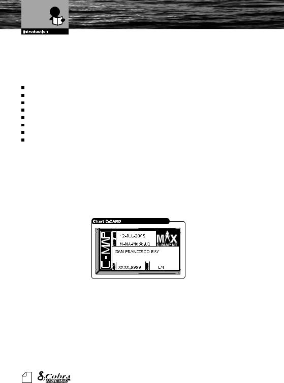
MC 600C Chart Details
The chartplotter has a built-in world map that can be used for Route planning. To use the chartplotter as a navigation aid, charts are required with detailed information for the area. This chart cartridge is called a C-CARD. C-CARDs are available from your local C-MAPTM dealer. See Chapter 6 for the insert/ remove C-CARD procedure. The C-CARD can be inserted by removing the faceplate.
2 |
Owner's Manual |

Table of Contents
1.MANUAL ORGANIZATION
1.1.TABLE OF CONTENTS
INTRODUCTION ................................................................................................................................. |
A1 |
OUR THANK S TO YOU ................................................................................................................................. |
A1 |
CUSTOMER ASSISTANCE .............................................................................................................................. |
A1 |
CONTROL AND INDICATORS ......................................................................................................................... |
A2 |
SOFTWARE BUTTONS FUNCTIONALITY ...................................................................................................... |
A2 |
SOFTWARE FEATURES ................................................................................................................................. |
A3 |
TECHNICAL SPECIFICATIONS ....................................................................................................................... |
A3 |
WARNINGS AND CAUTIONS ............................................................................................................................. |
1 |
SCREEN CLEANING PRECAUTIONS ................................................................................................................ |
1 |
WHAT IS IN THE BOX? .................................................................................................................................... |
2 |
MC 600C Chart Details .................................................................................................................................... |
2 |
1. MANUAL ORGANIZATION ............................................................................................................................. |
3 |
||
1.1. |
TABLE OF CONTENTS ......................................................................................................................... |
3 |
|
1.2. |
GENERAL OPERATION ....................................................................................................................... |
7 |
|
|
1.2.1. |
Button Conventions Used .......................................................................................................... |
7 |
|
1.2.2. |
Menu Description ....................................................................................................................... |
7 |
|
1.2.3. |
Selecting an option ..................................................................................................................... |
7 |
|
1.2.4. |
Alphanumeric Input Procedure ................................................................................................... |
8 |
2. BASIC OPERATION .................................................................................................................................. |
10 |
||
2.1. |
SWITCHING ON/OFF .......................................................................................................................... |
10 |
|
|
2.1.1 |
Switching On ............................................................................................................................ |
10 |
|
2.1.2 |
Switching Off ............................................................................................................................ |
10 |
|
2.1.3. |
Auto power On Description ...................................................................................................... |
10 |
2.2. |
INITIAL SETUP .................................................................................................................................. |
10 |
|
|
2.2.1. |
Definitions of Selections ........................................................................................................... |
11 |
2.3. ADJUSTING THE BACKLIGHTING AND CONTRAST ....................................................................... |
12 |
||
2.4. |
PAGE SURFING .................................................................................................................................. |
13 |
|
|
2.4.1. |
Pages selection ........................................................................................................................ |
13 |
2.5. |
DEMO MODE .................................................................................................................................. |
14 |
|
|
2.5.1. |
Full Demo ................................................................................................................................. |
14 |
|
2.5.2. |
Demo a Route .......................................................................................................................... |
14 |
|
2.5.3. Custom Demo .......................................................................................................................... |
14 |
|
2.6. MOVING AND ZOOMING ON CHART ................................................................................................ |
14 |
||
|
2.6.1. |
Pan .................................................................................................................................. |
14 |
|
2.6.2. |
Zoom .................................................................................................................................. |
15 |
|
2.6.3. |
Esc back to chart ...................................................................................................................... |
15 |
2.7. CHANGING DATA FIELDS ON MOST PAGES .................................................................................. |
15 |
||
|
2.7.1. |
Number of Data Fields ............................................................................................................. |
15 |
|
2.7.2. |
Change Data Fields ................................................................................................................. |
16 |
|
2.7.3. |
Available Data Options ............................................................................................................. |
17 |
2.8. CREATING A USER POINT ................................................................................................................ |
17 |
||
|
2.8.1. |
Creating a New Waypoint ........................................................................................................ |
17 |
|
2.8.2. |
Creating a New Mark ............................................................................................................... |
18 |
2.9. CREATING A BASIC ROUTE ............................................................................................................. |
18 |
||
2.10. USING GOTO .................................................................................................................................. |
19 |
||
2.11. USING FIND .................................................................................................................................. |
19 |
||
Nothing Comes Close to a Cobra® |
3 |

Table of Contents
|
|
|
|
|
|
|
|
|
|
2.12. USING MOB |
.................................................................................................................................. |
20 |
|||
|
|
|
2.12.1. Inserting MOB .......................................................................................................................... |
20 |
|||
|
|
|
2.12.2. Deleting MOB ........................................................................................................................... |
20 |
|||
3. PAGE INFORMATION AND OPERATION ................................................................................................... |
21 |
||||||
|
|
3.1. PAGE SELECTION AND PRESETS - SETUP .................................................................................... |
21 |
||||
3.2. |
WELCOME PAGE ............................................................................................................................... |
22 |
|||||
|
|
|
3.2.1. |
Operations ............................................................................................................................... |
22 |
||
3.3. |
CHART ONLY PAGE ........................................................................................................................... |
24 |
|||||
|
|
|
3.3.1. |
Description ............................................................................................................................... |
24 |
||
|
|
|
3.3.2. |
Operations ............................................................................................................................... |
24 |
||
|
|
|
|
3.3.2.1. Available Layouts of CHART Page ............................................................................ |
24 |
||
|
|
|
|
3.3.2.2. |
Changing Data Options ............................................................................................. |
24 |
|
|
|
|
|
3.3.2.3. |
Operations on User Points ......................................................................................... |
25 |
|
|
|
|
|
3.3.2.4. |
Software Buttons ....................................................................................................... |
25 |
|
|
|
|
3.3.3. |
Menu |
.................................................................................................................................. |
25 |
|
3.4. |
DATA PAGE |
.................................................................................................................................. |
27 |
||||
|
|
|
3.4.1. |
Description ............................................................................................................................... |
27 |
||
|
|
|
3.4.2. |
Operations ............................................................................................................................... |
27 |
||
|
|
|
|
3.4.2.1. |
Available Layouts of DATA Page ............................................................................... |
27 |
|
|
|
|
|
3.4.2.2. |
Changing Data Options ............................................................................................. |
27 |
|
|
|
|
|
3.4.2.3. |
On Screen Instructions .............................................................................................. |
28 |
|
|
|
|
3.4.3. |
Menu |
.................................................................................................................................. |
28 |
|
3.5. |
HIGHWAY PAGE ................................................................................................................................ |
30 |
|||||
|
|
|
3.5.1. |
Description ............................................................................................................................... |
30 |
||
|
|
|
3.5.2. |
Operations ............................................................................................................................... |
30 |
||
|
|
|
|
3.5.2.1. Available Layouts of HIGHWAY Page ....................................................................... |
31 |
||
|
|
|
|
3.5.2.2. ZOOM IN AND ZOOM OUT ...................................................................................... |
31 |
||
|
|
|
3.5.3. |
Menu |
.................................................................................................................................. |
31 |
|
|
|
3.6. SUN AND MOON PAGE ........................................................................................................................ |
32 |
||||
|
|
|
3.6.1. |
Description - “Telling” Tide ..................................................................................................... |
32 |
||
|
|
|
3.6.2. |
Operations ............................................................................................................................... |
32 |
||
|
|
|
|
3.6.2.1. Available Layouts of SUN and MOON Page. ............................................................. |
33 |
||
|
|
|
|
3.6.2.2. Finding the Nearest Tide Stations .............................................................................. |
33 |
||
|
|
|
|
3.6.2.3. Finding a Tide Station on a map ................................................................................ |
33 |
||
|
|
|
|
3.6.2.4. Changing the date for the Tide Chart ......................................................................... |
34 |
||
|
|
|
|
3.6.2.5. |
Various Animation Options ........................................................................................ |
34 |
|
3.7. |
FISH FINDER PAGE .......................................................................................................................... |
35 |
|||||
|
|
|
3.7.1. |
Description ............................................................................................................................... |
35 |
||
|
|
|
|
3.7.1.1. Understanding the Fish Finder Echogram ................................................................. |
37 |
||
|
|
|
3.7.2. |
Operations ............................................................................................................................... |
38 |
||
|
|
|
|
3.7.2.1. Available Layouts of FISH FINDER Page .................................................................. |
38 |
||
|
|
|
|
3.7.2.2. |
Changing Data Options ............................................................................................. |
38 |
|
|
|
|
|
3.7.2.3. Split Mode of the FISH FINDER Page ....................................................................... |
38 |
||
|
|
|
3.7.3. |
Menu |
.................................................................................................................................. |
38 |
|
3.8. |
COMBO MODE PAGE ........................................................................................................................ |
41 |
|||||
|
|
|
3.8.1. |
Description ............................................................................................................................... |
41 |
||
|
|
|
3.8.2. |
Operations ............................................................................................................................... |
41 |
||
|
|
|
|
3.8.2.1. Moving the location of the Chart Window ................................................................... |
41 |
||
|
|
|
|
3.8.2.2. Available Layouts of COMBO MODE Page ............................................................... |
42 |
||
|
|
|
|
3.8.2.3 |
Changing Data Options ............................................................................................. |
42 |
|
|
|
|
|
3.8.2.4. Changing the Size of Windows .................................................................................. |
42 |
||
|
|
|
3.8.3. |
Screen Control ......................................................................................................................... |
43 |
||
4 


 Owner's Manual

Table of Contents
|
|
|
|
|
|
|
3.9. |
............................................................................................................................SPLIT MODE PAGE |
44 |
||||
|
|
|
3.9.1. |
Description ............................................................................................................................... |
44 |
|
|
|
|
|
3.9.1.1. Available Layouts of SLIT MODE Page ..................................................................... |
44 |
|
|
|
|
|
3.9.1.2. Changing Data Options ............................................................................................. |
44 |
|
|
|
|
|
3.9.1.3. Changing the size of windows ................................................................................... |
45 |
|
|
|
|
|
3.9.1.4. Changing the Screen Control .................................................................................... |
45 |
|
|
|
|
3.9.2. |
Menu .................................................................................................................................. |
45 |
|
|
|
|
|
3.9.2.1. CHART Page ............................................................................................................. |
45 |
|
|
|
|
|
3.9.2.2. HIGHWAY Page ........................................................................................................ |
45 |
|
|
|
|
|
3.9.2.3. FISH FINDER Page ................................................................................................... |
45 |
|
|
|
3.10. GPS PAGE .................................................................................................................................. |
46 |
|||
|
|
|
3.10.1. Description ............................................................................................................................... |
46 |
||
|
|
|
|
3.10.1.1. Changing Data Options ............................................................................................. |
46 |
|
|
|
|
3.10.2. Menu .................................................................................................................................. |
47 |
||
|
|
3.11. SYSTEM PAGE .................................................................................................................................. |
48 |
|||
|
|
|
3.11.1. Description ............................................................................................................................... |
48 |
||
|
|
|
3.11.2. Each Setting Description .......................................................................................................... |
48 |
||
4. ADVANCED OPERATION ............................................................................................................................ |
49 |
|||||
4.1. |
MEASURE FUNCTION ....................................................................................................................... |
49 |
||||
4.2. |
ADVANCED WAYPOINT OPERATIONS ............................................................................................ |
49 |
||||
|
|
|
4.2.1. |
Deleting a Waypoint ................................................................................................................. |
49 |
|
|
|
|
4.2.2. |
Moving a Waypoint ................................................................................................................... |
50 |
|
|
|
|
4.2.3. |
Inserting a Waypoint ................................................................................................................ |
50 |
|
|
|
|
4.2.4. |
Editing a Waypoint ................................................................................................................... |
50 |
|
4.3. |
ROUTE OPERATIONS ........................................................................................................................ |
50 |
||||
|
|
|
4.3.1. Selecting existing and Naming new Routes ............................................................................. |
51 |
||
|
|
|
4.3.2. Basic Route List Operations ..................................................................................................... |
51 |
||
4.4. |
USING TRACK .................................................................................................................................. |
52 |
||||
4.5. |
USER POINTS LIST ............................................................................................................................ |
53 |
||||
|
|
|
4.5.1. Selecting Existing and naming new User Points ...................................................................... |
53 |
||
|
|
|
4.5.2. Basic User Point List Operations .............................................................................................. |
53 |
||
4.6. |
USER C-CARD OPERATIONS ........................................................................................................... |
54 |
||||
|
|
|
4.6.1. User C-CARD Page ................................................................................................................. |
54 |
||
|
|
|
4.6.2. |
Formatting User C-CARD ........................................................................................................ |
54 |
|
|
|
|
4.6.3. Saving file on User C-CARD .................................................................................................... |
55 |
||
|
|
|
4.6.4. Loading file from User C-CARD ............................................................................................... |
55 |
||
|
|
|
4.6.5. Deleting file from User C-CARD ............................................................................................... |
55 |
||
4.7. |
INFO |
|
.................................................................................................................................. |
56 |
||
|
|
|
4.7.1. |
Setting Automatic Info .............................................................................................................. |
56 |
|
|
|
|
4.7.2. |
Selecting Automatic Info .......................................................................................................... |
56 |
|
|
|
|
4.7.3. Info on objects with Pictures ..................................................................................................... |
56 |
||
|
|
|
4.7.4. Info Tree and Expanded Info page ........................................................................................... |
57 |
||
4.8. |
CURRENT PREDICTIONS .................................................................................................................. |
57 |
||||
4.9. |
DYNAMIC NAV AIDS .......................................................................................................................... |
57 |
||||
|
|
4.10. PICTURES .................................................................................................................................. |
58 |
|||
|
|
4.11. DSC CALLING .................................................................................................................................. |
58 |
|||
|
|
|
4.11.1. Advanced DSC for VHF Radio with NMEA 0183 Output .......................................................... |
59 |
||
|
|
|
4.11.2. Contact List .............................................................................................................................. |
59 |
||
5. SYSTEM PAGE SETTINGS .......................................................................................................................... |
60 |
|||||
|
|
5.1. SCREEN SHOT AND DESCRIPTIONS .............................................................................................. |
60 |
|||
5.2. |
OPERATIONS BY SETTING GROUP ................................................................................................. |
60 |
||||
Nothing Comes Close to a Cobra® |
5 |
Table of Contents
|
|
|
|
|
|
|
|
|
|
|
5.2.1. |
.......................................................................................................................Display Settings |
60 |
||
|
|
|
5.2.2. |
Chart Settings .......................................................................................................................... |
61 |
||
|
|
|
|
5.2.2.1. |
Chart Presentation ..................................................................................................... |
61 |
|
|
|
|
|
5.2.2.2. |
Depth Presentation .................................................................................................... |
63 |
|
|
|
|
|
5.2.2.3. |
Land Presentation ..................................................................................................... |
64 |
|
|
|
|
|
5.2.2.4. |
Advanced Chart Settings ........................................................................................... |
64 |
|
|
|
|
5.2.3. |
General |
.................................................................................................................................. |
67 |
|
|
|
|
5.2.4. |
Fish Finder Settings ................................................................................................................. |
67 |
||
|
|
|
|
5.2.4.1. |
Display Settings ......................................................................................................... |
68 |
|
|
|
|
|
5.2.4.2. |
Sensitivity Settings .................................................................................................... |
68 |
|
|
|
|
|
5.2.4.3. |
Transducer Settings .................................................................................................. |
69 |
|
|
|
|
5.2.5. |
Alarm Settings .......................................................................................................................... |
70 |
||
|
|
|
|
5.2.5.1. |
General Alarms .......................................................................................................... |
70 |
|
|
|
|
|
5.2.5.2. |
GPS Alarms ............................................................................................................... |
70 |
|
|
|
|
|
5.2.5.3. |
Fish Alarms ............................................................................................................... |
71 |
|
|
|
|
5.2.6. |
Units |
.................................................................................................................................. |
71 |
|
|
|
|
5.2.7. |
Pages On/Off ........................................................................................................................... |
72 |
||
|
|
|
5.2.8. |
GPS Settings ........................................................................................................................... |
72 |
||
|
|
|
5.2.9. |
Demo |
.................................................................................................................................. |
73 |
|
|
|
|
|
5.2.9.1. Custom Demo ............................................................................................................ |
73 |
||
|
|
|
5.2.10. Com Settings ........................................................................................................................... |
74 |
|||
|
|
|
5.2.11. About |
.................................................................................................................................. |
75 |
||
6. INSTALLATION |
.................................................................................................................................. |
76 |
|||||
6.1. |
BASIC |
|
|
.................................................................................................................................. |
76 |
||
|
|
|
6.1.1. |
Chartplotter Dimensions ........................................................................................................... |
76 |
||
|
|
|
6.1.2. C-CARD Inserting and Removing ............................................................................................ |
76 |
|||
|
|
|
6.1.3. Chartplotter Installation and Removing .................................................................................... |
77 |
|||
|
|
|
6.1.4. |
Wiring and Connectors ............................................................................................................. |
77 |
||
6.2. |
ADVANCED |
.................................................................................................................................. |
78 |
||||
|
|
|
6.2.1. |
External NMEA Connection ..................................................................................................... |
78 |
||
|
|
|
6.2.2. GPS Connection (on MC 600Cx with External GPS) ............................................................... |
78 |
|||
|
|
|
6.2.3. Autopilot and Basic DSC VHF Connection ............................................................................... |
78 |
|||
|
|
|
6.2.4. |
External Alarm Connection ...................................................................................................... |
79 |
||
|
|
|
6.2.5. |
Fish Finder ............................................................................................................................... |
79 |
||
6.3. |
MOUNTING THE GPS ANTENNA (ONLY on MC 600Cx model) ........................................................ |
79 |
|||||
|
|
|
6.3.1. |
Antenna Flush Mounting .......................................................................................................... |
80 |
||
7. MAINTENANCE |
.................................................................................................................................. |
81 |
|||||
7.1 |
SYSTEM TEST |
.................................................................................................................................. |
81 |
||||
8. OPTIONAL ACCESSORIES ......................................................................................................................... |
82 |
||||||
8.1. |
PC-PLANNER |
.................................................................................................................................. |
82 |
||||
8.2. |
MF 2500 FISH FINDER ....................................................................................................................... |
82 |
|||||
|
|
|
8.2.1. |
Transducers ............................................................................................................................. |
82 |
||
9. APPENDIX |
|
|
.................................................................................................................................. |
83 |
|||
9.1. |
TERMS |
.................................................................................................................................. |
83 |
||||
9.2. |
GPS |
|
|
.................................................................................................................................. |
90 |
||
|
|
|
9.2.1. How GPS Works ...................................................................................................................... |
90 |
|||
|
|
|
9.2.2. Position Fixing Accuracy: HDOP .............................................................................................. |
91 |
|||
|
|
9.3. WORLD CITY TIME ZONES ............................................................................................................... |
93 |
||||
INDEX |
|
|
|
.................................................................................................................................. |
94 |
||
6 


 Owner's Manual
General Operation
1.2.GENERAL OPERATION
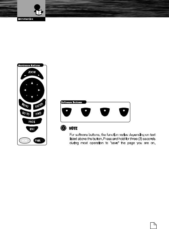
1.2.1.Button Conventions Used
Throughout this Owner’s Manual, the hardware buttons on the MC 600C are shown in bold capital letters, for example ENTER; the software buttons are shown in bold small capital letters, for example EDIT. See the following pictures.
Any menu operation and function activation in this Owner’s Manual is related to both MC 600Cx and MC 600Ci chartplotter models. Whenever it is necessary, a note has been inserted for the model with differences.
1.2.2.Menu Description
Many of the options listed under the Page Information and Operation Instructions should be read from start to finish. Duplicate items are not mentioned for each Page Operation. Example, Menu Item descriptions will not be listed for each page if they have already been described on the previous pages.
1.2.3.Selecting an option
When a menu window is shown on the screen, the procedure to follow for selecting the desired option is the same for every menu. For example, if you
Nothing Comes Close to a Cobra® |
7 |
General Operation
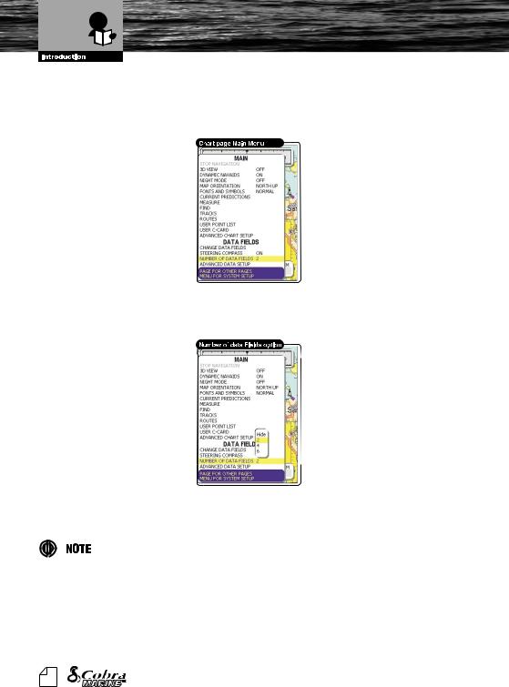
have activated the menu from the CHART Page (by pressing the MENU button) to select the option you want, “NUMBER OF DATA FIELDS” option, follow the procedure listed below:
1.Use the UP and DOWN CURSOR buttons to select the desired option,
“NUMBER OF DATA FIELDS”.
2.Press the ENTER button: a drop down box appears with the available selections “2”, “4”, “6”, “HIDE”.
3.Use the UP and DOWN CURSOR buttons to select a desired choice.
4.Press the ENTER button to confirm, or the ESC button to abort and return to the previous settings.
Pressing the RIGHT CURSOR button will sometimes perform like the ENTER button during this operation.
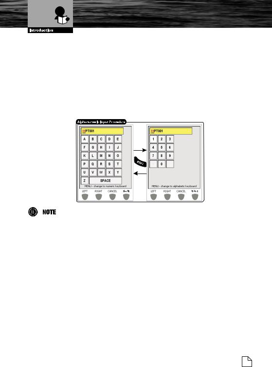
1.2.4.Alphanumeric Input Procedure
Information is keyed into the chartplotter for example when editing a Waypoint (see the following picture), or when entering Setup information.
8 |
Owner's Manual |
General Operation
When the field is highlighted:
1.Use the RIGHT or LEFT software buttons at the bottom to highlight the field you would like to change.
2.Use the UP, DOWN, RIGHT or LEFT CURSOR buttons to step through the available characters until the desired character is highlighted.
3.Press the ENTER button to confirm; the selected character appears in the highlighted field on the top line.
4.Repeat this procedure until you complete your entry.
5.Press the SAVE software button when the entry is complete.
This keypad is designed to reduce the number of button presses needed naming points and entering data. It can be disabled and the more conventional method used. If desired, it is disabled from the General settings of the SYSTEM Page.
Nothing Comes Close to a Cobra® |
9 |
Switching On/Off
2.BASIC OPERATION
Refer to the foldout on the front cover to identify the various controls and indicators on your chartplotter.
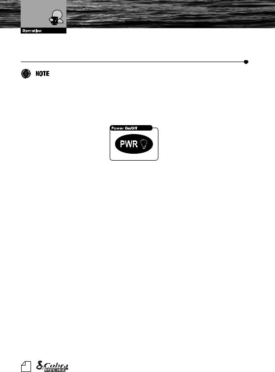
2.1.SWITCHING ON/OFF
Before powering On the chartplotter, check for the correct voltage (10-35 volt dc).
2.1.1Switching On
Press and hold the PWR button for one (1) second. The chartplotter shows you the Logo Screen, Caution Notice (press the ENTER button) and then the WELCOME Page in sequence. See the INITIAL SETUP Page instruction for first time switch On instructions.
2.1.2Switching Off
Press and hold the PWR button for three (3) seconds. A countdown timer appears on the screen, if you release the button before the countdown timer reaches zero, the chartplotter will remain On.
2.1.3.Auto power On Description
If you power Off the chartplotter during the normal working using an accessory switch (not pushing the PWR button), then the chartplotter will power On automatically when that same switch is turned back On.
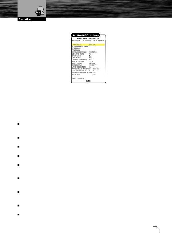
2.2.INITIAL SETUP
Initial power on settings page that asks the user to input crucial setup information. The FIRST TIME - GPS SETUP Page appears at power On after the Logo Screen.
10 |
Owner's Manual |
Initial Setup
2.2.1.Definitions of Selections
This menu allows you to select some of the basic setup information the first time the chartplotter is powered On. This information can be changed at any time either from the SYSTEM Page (see Chapter 5) or by resetting the chartplotter. Select the correct setup option and select “DONE” and press the ENTER button when complete. Please refer to section 1.2 for more information on how to enter information.
“LANGUAGES” - Selects the language in which you wish information to be displayed (for screen labels, menus and options, but it does not affect the map information).
“BOAT MANUFACTURER” (optional) - Enters the boat manufacturers name to be displayed on the initial Logo Screen.
“BOAT MODEL” (optional) - Enters the Model Name/Number of your boat to be displayed on the Logo Screen.
“BOAT NAME” (optional) - Enters the boat name to be displayed on the Logo Screen.
“COMPASS BEARINGS” - Selects either degrees magnetic or degrees true. If magnetic readings are selected the variation is computed automatically for every zone as soon as the chart is displayed.
“DISTANCE UNITS” - Sets the distance unit among the available choices. The default setting is Nm (Nautical Miles). Other options are Statute Miles (Sm) and Kilometers (Km).
“SPEED UNITS” - Sets the speed unit among the available units. The default setting is Knots (Nautical Miles/Hour). Other options are Miles per Hour (Mph) and Kilometers per Hour (Kph).
“DEPTH UNITS” - Sets the depth units among the available units. The default setting is Ft (Feet). Other options are Meters (Mt) and Fathoms (Ft). “GPS ALTITUDE UNITS” - Sets the altitude of GPS Antenna on the
Nothing Comes Close to a Cobra® 11
Initial Setup
medium sea level unit among the available units. The default setting is Ft (Feet). Other options are Meters (Mt) and Flight Level (FL).
“TIME REFERENCE” - Allows switching the Time Reference between UTC or Local. After entering the Local Time offset, your local time will be displayed. See Par. 5.2.6 for more detailed information.
“TIME FORMAT” - Sets you preferred time format. The default setting is 24 hour time.
“DATE FORMAT” - Sets you preferred date format between MM-DD-YY (month-day-year) and DD-MM-YY (day-month-year). The default setting is MM-DD-YY.
“WIND SPEED UNITS” - Sets the Wind Speed units among the available units. The default setting is Knots (Nautical Miles/Hour). Other options are M/S, BFT, Miles per Hour (Mph) and Kilometers per Hour (Kph).
“APPROXIMATE MAX SPEED” - This information will be used to set up the analog style speedometer gauge.
“CURRENT ENGINE HOURS” (optional) - Starting value that will be used for the engine hours gauge.
“WAYPOINT ARRIVAL ALARM” - Sets the distance you would like to have alarm sound when approaching a Waypoint.
“XTE ALARM” - Sets the distance you go off course before an off course alarm will sound.
“RESET DEFAULTS” - Changes all the settings on this page back to the original settings.
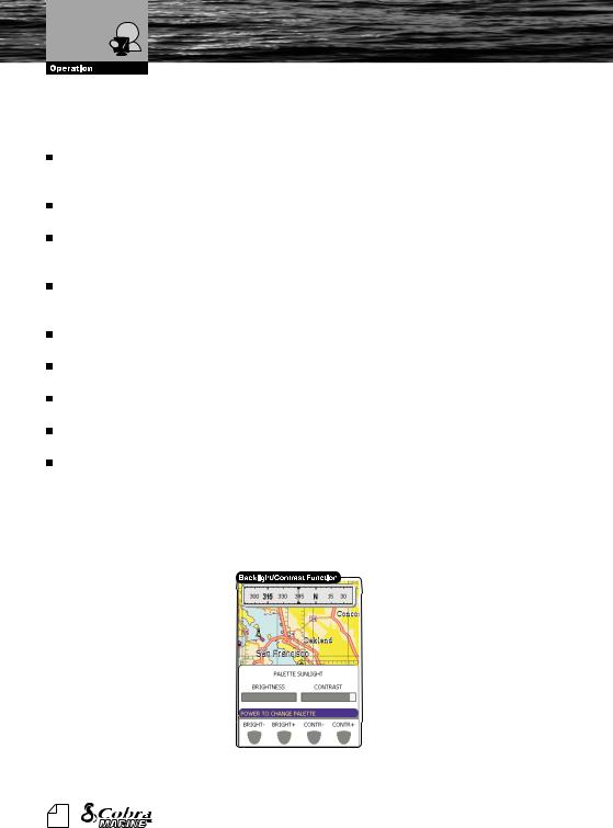
2.3. ADJUSTING THE BACKLIGHTING AND CONTRAST
You can change the level of backlight and contrast for the screen. 1. Press the PWR button. On the screen appears:
2. Use the software buttons to adjust the backlight and contrast levels.
12 |
Owner's Manual |
Backlight and Contrast
Page Surfing
3.Wait or press the ENTER button to return to the chart screen with the new light levels retained.
Continuously pressing the PWR button from this screen will toggle you through the available color palettes.
2.4.PAGE SURFING
There are many different pages of data and information available. You can select the page you wish “by surfing” among the available pages.
2.4.1.Pages selection
Pressing the PAGE button causes TABs to appear with the pages that you can scroll through. Continually pressing the PAGE button or the RIGHT and LEFT CURSOR buttons allow you to scroll forwards or backwards through the available pages. The TABs disappear after several seconds allowing you to resume full operation of the selected page.
Please note that these available pages can be customized from the settings page (see Par. 3.1).
The option of having the page TABs appear at the top of the page can be turned Off from the SYSTEM Page in the General settings menu.
Nothing Comes Close to a Cobra® 13

Demo Mode
2.5.DEMO MODE
DEMO MODE is great for practicing the actual use of a product when the satellites signals and internal alarms are not available. When the device is in DEMO MODE, the GPS receiver is turned Off, so it is impossible to navigate.
Do not try to navigate in a DEMO MODE. While the DEMO MODE is turned On, the GPS receiver is not active. All satellite signal strength bars are only a simulation and do not indicate any actual satellite signals.
DEMO MODE can be selected from the WELCOME Page (see Par. 3.2) or from the SYSTEM Page (see Par. 5.2.9) .
Selecting the DEMO MODE would bring up the choice of three options for demo. The DEMO MODEs are:
2.5.1.Full Demo
This mode is designed for in store or on display demonstration. This unit will automatically scroll through various displays and demonstrate the product.
2.5.2.Demo a Route
This mode allows the user to select a Route that they have already planned.
2.5.3.Custom Demo
This mode allows you to enter a desired course and speed for the demonstration. The simulated GPS position will start directly from the Pointers position on the chart.
2.6.MOVING AND ZOOMING ON CHART
Use the CURSOR buttons to move around or Pan the chart. Also use the ZOOM IN and ZOOM OUT buttons to change the chart scale so that a smaller or larger area is shown on the chart.
2.6.1.Pan
Controlled by the CURSOR buttons, the Pointer is an important tool that can be used to pan to other map locations, mark and edit Waypoints and Routes and review information about on-screen map items and Waypoints. Use the
14 |
Owner's Manual |

Moving and Zooming on Chart
map Pointer to pan away from your present position and scroll to other map areas even outside of your current detail coverage. While panning past the edge of the current map display, the screen actively scrolls forward to provide continuous map coverage.
2.6.2.Zoom
Zoom function is generally used to change a map scale and show relevant detail content.
ZOOM OUT - Press the ZOOM OUT button to change the scale and show less details of a larger area.
ZOOM IN – Press the ZOOM IN button to show more details of a smaller area.
2.6.3.Esc back to chart
The function of the ESC button is to come back to the CHART Page from every other page. The ESC button will also move back from a selection menu or to clear the screen.
Please note that the ESC button is used to come back to original map Pointer location and a map scale after zooming and panning.
2.7.CHANGING DATA FIELDS ON MOST PAGES
It is possible to change the number of data fields shown at the bottom of most Pages. The number of fields and the value displayed in the field can be changed by selecting the MAIN Menu and then either the “NUMBER OF DATA FIELDS” or “CHANGE DATA FIELDS” option.
2.7.1.Number of Data Fields
Most pages give the ability to adjust the number of fields displayed on a given page. The available choices are predefined in the MAIN Menu. To change the number of data fields follow the procedure below:
1.Press the MENU button. The MAIN Menu will be activated.
2.Use the UP and DOWN CURSOR buttons to select the “NUMBER OF DATA FIELDS” option.
3.Press the ENTER button to access the available selections.
4.Use the UP and DOWN CURSOR buttons to select a desired choice.
5.Press the ENTER button to confirm, or the ESC button to abort and return to the previous settings.
Nothing Comes Close to a Cobra® 15
Changing Data Fields
2.7.2.Change Data Fields
Each data field present on a given page (no matter the number of data fields) can be customized to obtain the best navigational information.
1.Press the MENU button. The MAIN Menu will be activated.
2.Use the UP and DOWN CURSOR buttons to select the “CHANGE DATA FIELDS” option.
3.Press the ENTER button to confirm. A yellow frame appears around one of the data fields.
4.Use the UP, DOWN, RIGHT and LEFT CURSOR buttons to highlight and choose an individual data field.
5.Press the ENTER button to display the available data options for the chosen data field.
6.Use the UP and DOWN CURSOR buttons move through the options.
7.Press the ENTER button to select the on screen option or the ESC button to cancel and return to the previously selected data.
You can also complete this by holding the MENU button. This will place a yellow frame around one of the fields as per step 3 above.
16 |
Owner's Manual |
Available Data Options
Creating a User Point
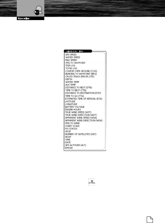
2.7.3.Available Data Options
All the available choices for the Data Fields are presented in the table below. Keep in mind that some of them are characteristic only to one specified page. The yellow bar on the right will scroll down as you move down the list.
2.8.CREATING A USER POINT
A User Point is an object that you can place on the charts to mark a specific point. The chartplotter features two types of User Points: Marks and Waypoints.
2.8.1. Creating a New Waypoint
A Waypoint is created when entering a Route:
1.Move the Pointer to the desired location on the chart.
2.Press the ENTER button.
3.Use the UP or DOWN CURSOR button to select “NEW WAYPOINT” and press the ENTER button. The new Waypoint is placed.
Nothing Comes Close to a Cobra® 17
Creating a Basic Route
4. Move the Pointer off the location to accept.
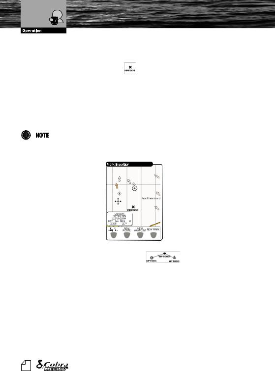
2.8.2.Creating a New Mark
A Mark can be created at anytime. Marks are used for marking points outside of a Route.
1.Move the Pointer to the desired location on the chart.
2.Press the ENTER button.
3.Use the UP or DOWN CURSOR button to select “NEW MARK” and press the ENTER button. The new Mark appears on your Pointer.
4.Move the Pointer off the location to accept.
You can also use the shortcut software buttons that appear when moving the Pointer. See the following picture:
2.9. CREATING A BASIC ROUTE
To create a Route:
1.Move the Pointer to the desired location on the chart.
2.Press the ENTER button.
3.Use the UP or DOWN CURSOR button to select “NEW WAYPOINT” and press the ENTER button. This places the first Waypoint of the new Route on your Pointer position. To place the next Waypoints of the Route repeat the above procedure.
4.Move the Pointer off the location to accept or press the ENTER button to edit.
18 |
Owner's Manual |
Using Goto and Find
2.10. USING GOTO
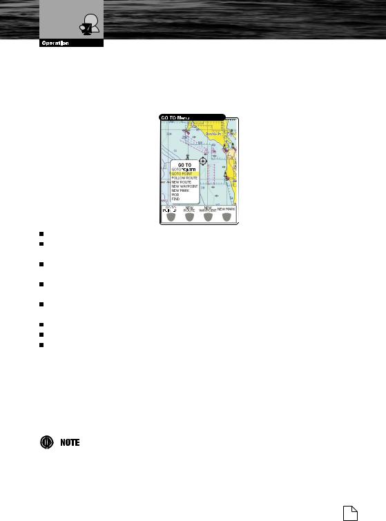
The GOTO function allows instant plotting of course to selected target. After pressing the GOTO button on most of the pages, the sub-menu on a Pointer position appears and it is possible to choose beneath mentioned options:
“GOTO POINTER” - Sets the Pointer location as the destination.
“GOTO POINT” - Shows the “User Point” list, that gives information on all stored User Points.
“FOLLOW ROUTE” - Brings up the “Select Route” list with the most recently used highlighted.
“NEW ROUTE” - Brings up the “Selected Route” list but with the next open Route highlighted. Software button choices are: EDIT, ACCEPT. “NEW WAYPOINT” - A new Waypoint is created and set as the destination Waypoint.
“NEW MARK” - A new Mark is created.
“MOB” - Man OverBoard (MOB) function. See Par. 2.12 for details. “FIND” - Find function. See Par. 2.11 for details.
2.11. USING FIND
The Find function allows searching for the nearest Ports, Port Services, Tide Stations, Wrecks, Obstructions loaded on the C-CARD or it centers the screen over a selected User Point or at desired Coordinates. When you press the FIND button (or choose Find from a menu option) a list of available objects to search is shown.
A Warning message is shown when activating the Find function if no C-CARD inserted.
Nothing Comes Close to a Cobra® 19

Using MOB
2.12. USING MOB
If a person or object is lost overboard and you need to return to the location, use the MOB (Man OverBoard) function. This function enables you to simultaneously mark and set a course to a location for quick response to emergency situations.
To activate the MOB function, a valid GPS fix must be available.
2.12.1. Inserting MOB
To activate a MOB function follow the procedure below:
1.Press the MOB button. A dialog box with a message “MOB is activated” will appear on a screen and a MOB Waypoint will be created.
2.If the NMEA output is turned On, the warning dialog box is given: “Turn off autopilot before setting MOB point as destination”
2.12.2. Deleting MOB
To cancel the MOB function
1.Use the CURSOR button to move the Pointer over the MOB icon.
2.Choose the DELETE or STOP NAV software buttons at the bottom of the display.
20 |
Owner's Manual |
Page Selection and Presets
3.PAGE INFORMATION AND OPERATION
3.1.PAGE SELECTION AND PRESETS - SETUP
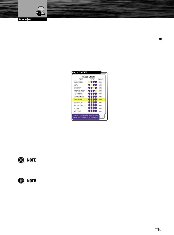
Any page can be turned ON or OFF using the following procedure:
1.Press the PAGE button several times to select “SYSTEM” and then press the ENTER button.
2.Use the UP and DOWN CURSOR buttons to select the “PAGES ON/ OFF” option and then press the ENTER button.
3.Press the ENTER button to change the page status (On or Off).
4.Press one of the bottom software buttons to assign it as a short cut to the desired page. The RIGHT and LEFT CURSOR buttons can also be used to change the selection if the page has already been assigned a button.
During future operations the ON pages can be selected using the PAGE button which is generally used to scroll through all available pages.
Pages containing certain data like the Fish Finder and Combo are not accessible unless that optional module is connected.
Press and hold one of the software buttons from any of the main pages to save that as one of quick access pages.
Nothing Comes Close to a Cobra® 21
Welcome Page
3.2. WELCOME PAGE
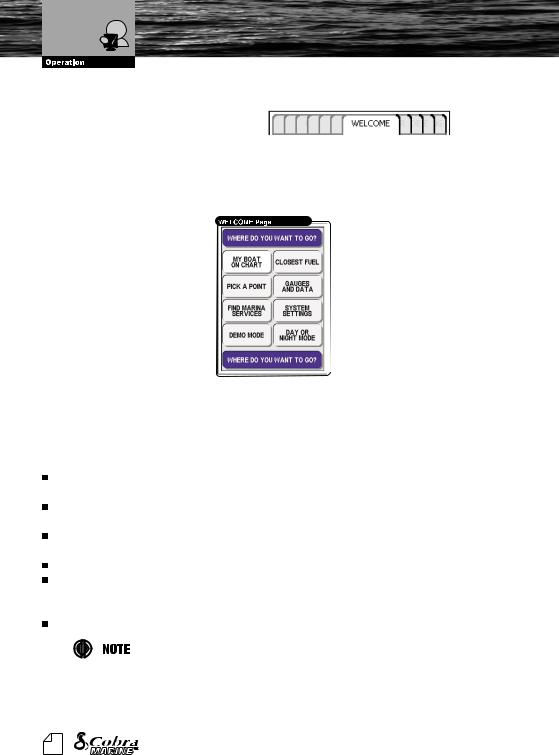
The WELCOME Page is activated by default on Power On and appears after the GPS position lock. Use the WELCOME Page to go to the most commonlyused features on the chartplotter that are otherwise more difficult to access. All of the options in these large selection boxes are also available from other pages and selections.
3.2.1.Operations
The CURSOR buttons are used to choose an individual feature box. Press the ENTER button to display the available feature’s options. After selection use the PAGE button to return to the WELCOME Page. 8 different options are available from this page:
“MY BOAT ON CHART”: Goes back to the CHART Page, centered on the vessel’s position.
“CLOSEST FUEL”: Goes right to the list of closest Fuel Stations with distance and bearing listed.
“PICK A POINT”: Goes to the predefined User Point list with the closest point highlighted.
“GAUGES AND DATA”: Goes to the DATA Page.
“FIND MARINE SERVICES”: Shows an icon selection table. Use the CURSOR button to highlight an icon. A description of the type of service is listed. Press the ENTER button to search for this type of service. “SYSTEM SETTINGS”: Goes directly to the SYSTEM Page for setup info.
The System Page can also be accessed by pressing the MENU button twice from most pages.
22 |
Owner's Manual |

Welcome Page
“DEMO MODE”: Links to a secondary set of selection boxes. The DEMO Mode is specified in further detail in Par. 2.5.
“DAY OR NIGHTWATCHTM MODE”: Selection toggles between Day and NightwatchTM depending on what mode the display is in at the time of selection.
The screen will be difficult to read if the chartplotter is in NightwatchTM mode and the sun is to bright. With the chartplotter on, continuously pressing the PWR button will get the chartplotter out of NightwatchTM mode.
Nothing Comes Close to a Cobra® 23
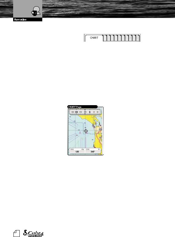
Chart Only Page
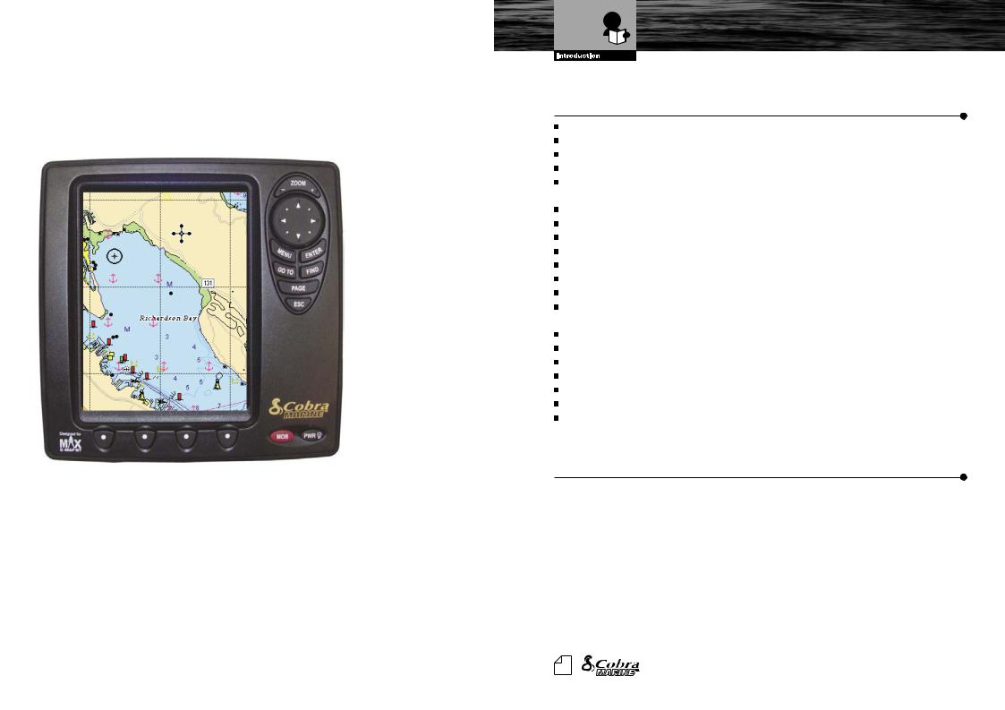
3.3. CHART ONLY PAGE
The CHART Page is the main page of the chartplotter. From this page the user can select the desired map, get information about cartographic objects on the maps, see the vessel position, its direction and speed, place points (Marks, Waypoints), set a destination point and display additional features. The chartplotter is provided with worldwide background cartography while the detailed charts of the desired area are available on data cartridges.
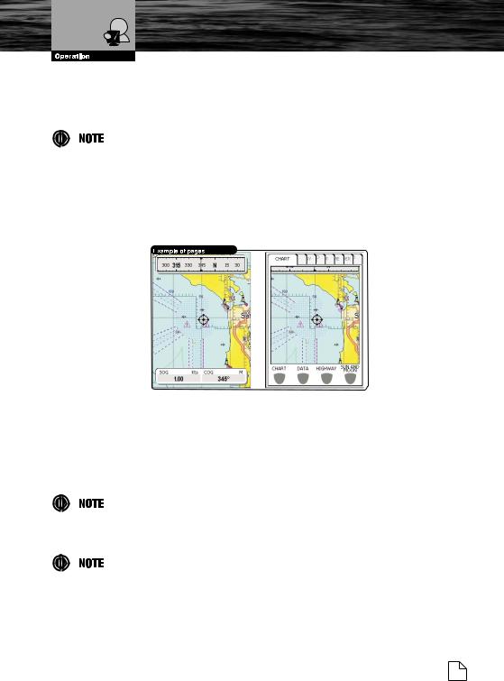
3.3.1.Description
The picture below shows the CHART Page layout with displayed data fields and a steering compass added at the top. It is possible to customize all fields shown in the page as described later in this paragraph. The central section of the screen provides visual guidance of a chart and the bottom of the page is designed for navigation data display.
3.3.2.Operations
The CHART Page is used for display of electronic cartography, creating and using the User Points, plotting position and navigational data.
3.3.2.1. Available Layouts of CHART Page
The data fields of the CHART Page can be customized as HIDE, 2, 4 or 6 through the MENU button. By default the CHART Page is specified for 2 data fields and a Steering Compass added over a Horizon. The Compass can be turned Off in the Main Menu of the CHART Page by pressing the MENU button.
3.3.2.2. Changing Data Options
The content of each data field can be adjusted to the user’s requirements. To customize data options follow the procedure described in Par. 2.7.2 Changing Data Fields.
24 |
Owner's Manual |
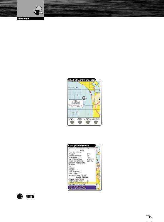
Chart Only Page
3.3.2.3. Operations on User Points
Using the ENTER button we are able to create, edit and delete various User Points used during further navigation. Those advanced operations are explained in detail in Chapter 4.
3.3.2.4. Software Buttons
The functional software buttons are activated when moving the Pointer with the CURSOR buttons. They acts as a shortcuts for the GOTO functions
including: GO TO POINTER, NEW ROUTE, NEW WAYPOINT, and NEW MARK. These
functions time out after several seconds. The ESC button disables these software buttons for several more seconds.
3.3.3.Menu
The MAIN Menu (selected through the MENU button) of the CHART Page provides the operations for the chart display.
Some of the more commonly accessed features are listed first.
Nothing Comes Close to a Cobra® 25
Loading...