

Clevo NH55HHQ, NH55HJQ, NH55HKQ, NH58HHQ, NH58HJQ service manual
...
NH55HHQ / NH55HJQ / NH55HKQ /
NH58HHQ / NH58HJQ / NH58HKQ


Notebook Computer
NH55HHQ / NH55HJQ / NH55HKQ / NH58HHQ / NH58HJQ /
NH58HKQ
Preface
Service Manual
Preface
I

Preface
Preface
Notice
The company reserves the right to revise this publication or to change its contents without notice. Information contained
herein is for reference only and does not constitute a commitment on the part of the manufacturer or any subsequent vendor. They assume no responsibility or liability for any errors or inaccuracies that may appear in this publication nor are
they in anyway responsible for any loss or damage resulting from the use (or misuse) of this publication.
This publication and any accompanying software may not, in whole or in part, be reproduced, translated, transmitted or
reduced to any machine readable form without prior consent from the vendor, manufacturer or creators of this publication, except for copies kept by the user for backup purposes.
Brand and product names mentioned in this publication may or may not be copyrights and/or registered trademarks of
their respective companies. They are mentioned for identification purposes only and are not intended as an endorsement
of that product or its manufacturer.
Version 1.0
May 2021
Trademarks
Intel and Intel Core are trademarks of Intel Corporation.
Windows® is a registered trademark of Microsoft Corporation.
Other brand and product names are trademarks and /or registered trademarks of their respective companies.
II

About this Manual
This manual is intended for service personnel who have completed sufficient training to undertake the maintenance and
inspection of personal computers.
It is organized to allow you to look up basic information for servicing and/or upgrading components of the NH55HHQ
/ NH55HJQ / NH55HKQ / NH58HHQ / NH58HJQ / NH58HKQ series notebook PC.
The following information is included:
Chapter 1, Introduction, provides general information about the location of system elements and their specifications.
Chapter 2, Disassembly, provides step-by-step instructions for disassembling parts and subsystems and how to upgrade
elements of the system.
Preface
Appendix A, Part Lists
Appendix B, Schematic Diagrams
Preface
III

Preface
Preface
IMPORTANT SAFETY INSTRUCTIONS
Follow basic safety precautions, including those listed below, to reduce the risk of fire, electric shock and injury to persons when using any electrical equipment:
1. Do not use this product near water, for example near a bath tub, wash bowl, kitchen sink or laundry tub, in a wet
basement or near a swimming pool.
2. Avoid using a telephone (other than a cordless type) during an electrical storm. There may be a remote risk of electrical shock from lightning.
3. Do not use the telephone to report a gas leak in the vicinity of the leak.
4. Use only the power cord and batteries indicated in this manual. Do not dispose of batteries in a fire. They may
explode. Check with local codes for possible special disposal instructions.
5. This product is intended to be supplied by a Listed Power Unit as follows:
• AC Input of 100 - 240V, 50 - 60Hz, DC Output of 19.5V, 6.15A (120 Watts) or 19.5V, 7.7A (150 Watts) minimum AC/DC
Adapter.
IV
FCC Statement
This device complies with Part 15 of the FCC Rules. Operation is subject to the following two conditions:
This device may not cause harmful interference.
This device must accept any interference received, including interference that may cause undesired operation.
Instructions for Care and Operation
The notebook computer is quite rugged, but it can be damaged. To prevent this, follow these suggestions:
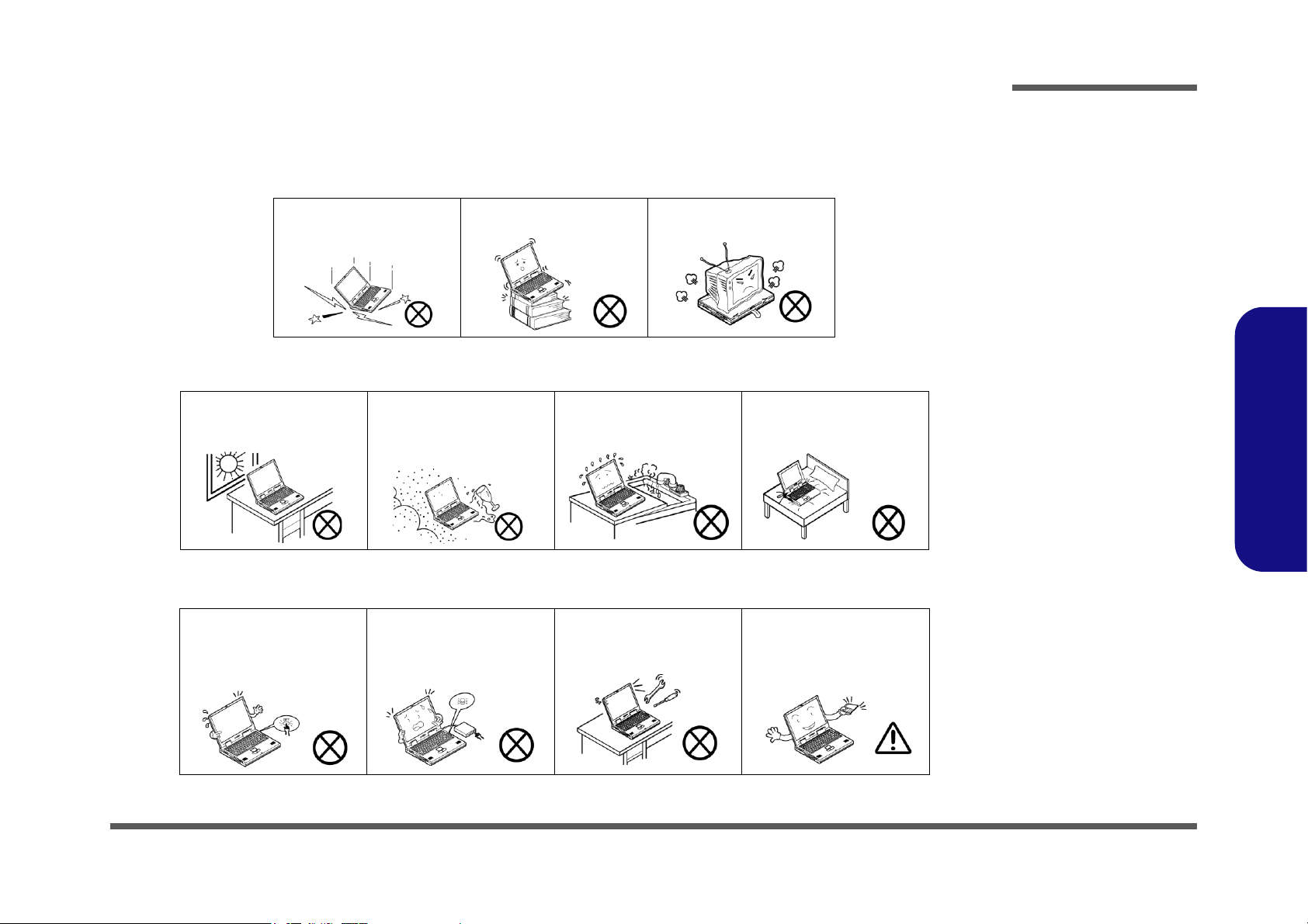
1. Don’t drop it, or expose it to shock. If the computer falls, the case and the components could be damaged.
Preface
Do not expose the computer
to any shock or vibration.
Do not place it on an unstable
surface.
Do not place anything heavy
on the computer.
2. Keep it dry, and don’t overheat it. Keep the computer and power supply away from any kind of heating element. This
is an electrical appliance. If water or any other liquid gets into it, the computer could be badly damaged.
Do not expose it to excessive
heat or direct sunlight.
Do not leave it in a place
where foreign matter or moisture may affect the system.
Don’t use or store the computer in a humid environment.
Do not place the computer on
any surface which will block
the vents.
3. Follow the proper working procedures for the computer. Shut the computer down properly and don’t forget to save
your work. Remember to periodically save your data as data may be lost if the battery is depleted.
Do not turn off the power
until you properly shut down
all programs.
Do not turn off any peripheral
devices when the computer is
on.
Do not disassemble the computer by yourself.
Perform routine maintenance
on your computer.
Preface
V
Preface
Power Safety
Warning
Before you undertake
any upgrade procedures, make sure that
you have turned off the
power, and disconnected all peripherals
and cables (including
telephone lines and
power cord). It is advisable to also remove
your battery in order to
prevent accidentally
turning the machine
on.
4. Avoid interference. Keep the computer away from high capacity transformers, electric motors, and other strong mag-
netic fields. These can hinder proper performance and damage your data.
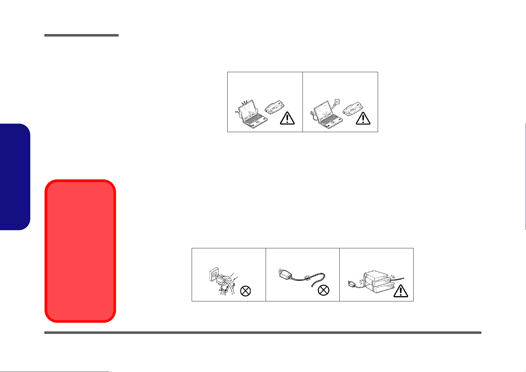
5. Take care when using peripheral devices.
Preface
VI
Use only approved brands of
peripherals.
Unplug the power cord before
attaching peripheral devices.
Power Safety
The computer has specific power requirements:
• Only use a power adapter approved for use with this computer.
• Your AC adapter may be designed for international travel but it still requires a steady, uninterrupted power supply. If you are
unsure of your local power specifications, consult your service representative or local power company.
• The power adapter may have either a 2-prong or a 3-prong grounded plug. The third prong is an important safety feature; do
not defeat its purpose. If you do not have access to a compatible outlet, have a qualified electrician install one.
• When you want to unplug the power cord, be sure to disconnect it by the plug head, not by its wire.
• Make sure the socket and any extension cord(s) you use can support the total current load of all the connected devices.
• Before cleaning the computer, make sure it is disconnected from any external power supplies.
Do not plug in the power
cord if you are wet.
Do not use the power cord if
it is broken.
Do not place heavy objects
on the power cord.

Battery Precautions
Battery Disposal
The product that you have purchased contains a rechargeable battery. The battery is recyclable. At the end of its useful life, under various state and local laws, it may be illegal to dispose of this battery into the municipal waste stream. Check with your local solid waste
officials for details in your area for recycling options or proper disposal.
Caution
Danger of explosion if battery is incorrectly replaced. Replace only with the same or equivalent type recommended by the manufacturer.
Discard used battery according to the manufacturer’s instructions.
Battery Level
Click the battery icon in the taskbar to see the current battery level and charge status. A battery that drops below a level of 10%
will not allow the computer to boot up. Make sure that any battery that drops below 10% is recharged within one week.
• Only use batteries designed for this computer. The wrong battery type may explode, leak or damage the computer.
• Do not continue to use a battery that has been dropped, or that appears damaged (e.g. bent or twisted) in any way. Even if the
computer continues to work with a damaged battery in place, it may cause circuit damage, which may possibly result in fire.
• Recharge the batteries using the notebook’s system. Incorrect recharging may make the battery explode.
• Do not try to repair a battery pack. Refer any battery pack repair or replacement to your service representative or qualified service
personnel.
• Keep children away from, and promptly dispose of a damaged battery. Always dispose of batteries carefully. Batteries may explode
or leak if exposed to fire, or improperly handled or discarded.
• Keep the battery away from metal appliances.
• Affix tape to the battery contacts before disposing of the battery.
• Do not touch the battery contacts with your hands or metal objects.
Battery Guidelines
The following can also apply to any backup batteries you may have.
• If you do not use the battery for an extended period, then remove the battery from the computer for storage.
• Before removing the battery for storage charge it to 60% - 70%.
• Check stored batteries at least every 3 months and charge them to 60% - 70%.
Preface
Preface
VII
Preface
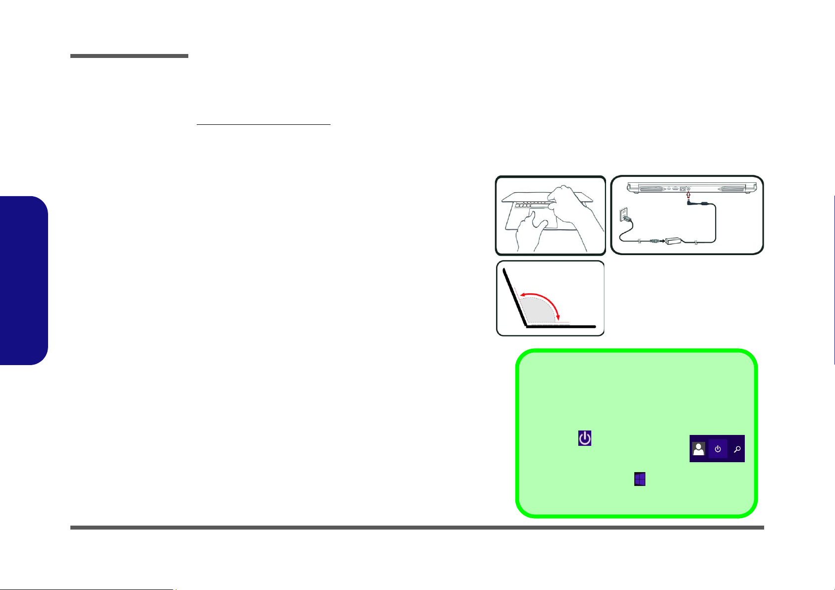
Figure 1
Opening the Lid/LCD/
Computer with AC/DC
Adapter Plugged-In
Shut Down
Note that you should always shut your computer down by
choosing the Shut down command in Windows (see below). This will help prevent hard disk or system problems.
Click the icon in the Start Screen and
choose Shut down from the menu.
Or
Right-click the Start button
at the bottom of the Start
Screen or the Desktop and choose Shut down or sign out
> Shut down from the context menu.
130°
Preface
Related Documents
You may also need to consult the following manual for additional information:
User’s Manual on CD/DVD
This describes the notebook PC’s features and the procedures for operating the computer and its ROM-based setup program. It also describes the installation and operation of the utility programs provided with the notebook PC.
System Startup
1. Remove all packing materials.
2. Place the computer on a stable surface.
3. Insert the battery and make sure it is locked in position.
4. Securely attach any peripherals you want to use with the
computer (e.g. keyboard and mouse) to their ports.
5. When first setting up the computer use the following pro-
cedure (as to safeguard the computer during shipping, the
battery will be locked to not power the system until first connected to the AC/DC adapter and initially set up as below):
• Attach the AC/DC adapter cord to the DC-In jack on the rear
of the computer, then plug the AC power cord into an outlet,
and connect the AC power cord to the AC/DC adapter. The
battery will now be unlocked.
6. Use one hand to raise the
angle
(do not exceed 130 degrees); use the other hand (as
illustrated in Figure 1) to support the base of the computer
(Note: Never lift the computer by the lid/LCD).
7. Press the power button to turn the computer “on”.
lid/LCD to a comfortable viewing
VIII

Contents
Preface
Introduction ..............................................1-1
Overview .........................................................................................1-1
Specifications .................................................................................. 1-2
External Locator - Top View with LCD Panel Open ......................1-4
External Locator - Front & Right Side Views .................................1-5
External Locator - Left Side & Rear View .....................................1-6
External Locator - Bottom View ..................................................... 1-7
Mainboard Overview - Top (Key Parts) .........................................1-8
Mainboard Overview - Bottom (Key Parts) .................................... 1-9
Mainboard Overview - Top (Connectors) ..................................... 1-10
Mainboard Overview - Bottom (Connectors) ...............................1-11
Disassembly ...............................................2-1
Overview .........................................................................................2-1
Maintenance Tools ..........................................................................2-2
Connections ..................................................................................... 2-2
Maintenance Precautions .................................................................2-3
Disassembly Steps ...........................................................................2-4
Removing the Battery ......................................................................2-5
Removing the Keyboard ..................................................................2-6
Removing the Hard Disk Drive ....................................................... 2-7
Removing the System Memory (RAM) ..........................................2-9
Removing the M.2 SSD Module ...................................................2-10
Removing the Wireless LAN Module ........................................... 2-11
Wireless LAN, Combo Module Cables .........................................2-12
Removing the CCD .......................................................................2-13
Part Lists ..................................................A-1
Part List Illustration Location ........................................................A-2
Top .................................................................................................A-3
Bottom ............................................................................................ A-4
Main Board ................................................................................... A-5
HDD .............................................................................................. A-6
LCD (NH55HHQ/NH55HJQ/NH55HKQ) .................................... A-7
LCD (NH58HHQ/NH58HJQ/NH58HKQ) .................................... A-8
Schematic Diagrams................................. B-1
System Block Diagram ...................................................................B-2
Processor 1/8 ...................................................................................B-3
Processor 2/8 ...................................................................................B-4
Processor 3/8 ...................................................................................B-5
Processor 4/8 ...................................................................................B-6
Processor 5/8 ...................................................................................B-7
Processor 6/8 ...................................................................................B-8
Processor 7/8 ...................................................................................B-9
Processor 8/8 .................................................................................B-10
PCH 1/8 ........................................................................................B-11
PCH 2/8 ........................................................................................B-12
PCH 3/8 ........................................................................................B-13
PCH 4/8 ........................................................................................B-14
PCH 5/8 ........................................................................................B-15
PCH 6/8 ........................................................................................B-16
PCH 7/8 ........................................................................................B-17
PCH 8/8 ........................................................................................B-18
DDR4 SO_DIMM_0 ....................................................................B-19
DDR4 SO_DIMM_1 ....................................................................B-20
VGA PCI Express .........................................................................B-21
GPU Frame Buffer A/B ................................................................B-22
Frame Buffer A .............................................................................B-23
Frame Buffer A .............................................................................B-24
Frame Buffer B .............................................................................B-25
Frame Buffer B .............................................................................B-26
Preface
IX

Preface
VGA NVVDD Coupling .............................................................. B-27
Straps and XTAL ......................................................................... B-28
IFP I/O Interface ........................................................................... B-29
Misc - GPIO, I2C and ROM ........................................................B-30
NVIDIA Power Sequence ............................................................ B-31
GPU NVVDD, FBVDDQ ............................................................ B-32
GPU GND .................................................................................... B-33
Panel ............................................................................................. B-34
mDP .............................................................................................. B-35
HDMI ........................................................................................... B-36
Audio Codec ................................................................................. B-37
Card Reader & LAN_RTL5227S ................................................. B-38
LAN RTL8111H RTD3 ............................................................... B-39
USB Type-A ................................................................................. B-40
USB Type-C ................................................................................. B-41
M.2 PCIE 4X/SATA SSD ............................................................ B-42
Preface
M.2 WLAN+BT, PCIE 4X SSD .................................................. B-43
HDD, Click TP, Audio ................................................................. B-44
LED, CCD, Power SW Bd. .......................................................... B-45
KBC-ITE IT5570 .........................................................................B-46
RGB KB, Fan ............................................................................... B-47
VDD3, VDD5 ............................................................................... B-48
1V8_RUN/AON, NV3V3, 3.3VS ................................................ B-49
3V, 5V, 3VS, 5VS ........................................................................ B-50
VCCST, VCCSTG, 1.8VS ........................................................... B-51
VNN / V1.05 ................................................................................ B-52
VCCIN ......................................................................................... B-53
VCCIN Output .............................................................................B-54
AC_In, Charger ............................................................................ B-55
VCCIN AUX ................................................................................ B-56
DDR 1.2V / 0.6VS, 2.5V ............................................................. B-57
NVVDD1 ..................................................................................... B-58
NVVDD2 ......................................................................................B-59
PEX_VDD ....................................................................................B-60
FBVDDQ ......................................................................................B-61
OVRM ..........................................................................................B-62
Click Board ...................................................................................B-63
LED Board ....................................................................................B-64
Audio Board ..................................................................................B-65
Audio Board + Redriver ...............................................................B-66
NH77 PW Board ...........................................................................B-67
NH50 PW Board ...........................................................................B-68
NH55 PW Board ...........................................................................B-69
Power Sequence ............................................................................B-70
Power Map ....................................................................................B-71
X

Chapter 1: Introduction
Overview
This manual covers the information you need to service or upgrade the NH55HHQ / NH55HJQ / NH55HKQ /
NH58HHQ / NH58HJQ / NH58HKQ series notebook computer. Information about operating the computer (e.g. getting
started, and the Setup utility) is in the User’s Manual. Information about dri-vers (e.g. VGA & audio) is also found in the
User’s Manual. The manual is shipped with the computer.
Operating systems (e.g. Windows 10, etc.) have their own manuals as do application softwares (e.g. word processing and
database programs). If you have questions about those programs, you should consult those manuals.
The NH55HHQ / NH55HJQ / NH55HKQ / NH58HHQ / NH58HJQ / NH58HKQ series notebook is designed to be
upgradeable. See Disassembly on page 2 - 1 for a detailed description of the upgrade procedures for each specific component. Please take note of the warning and safety information indicated by the “” symbol.
The balance of this chapter reviews the computer’s technical specifications and features.
Introduction
1.Introduction
Overview 1 - 1
Introduction
Latest Specification Information
The specifications listed here are correct at the
time of sending them to the press. Certain items
(particularly processor types/speeds) may be
changed, delayed or updated due to the manufacturer's release schedule. Check with your
service center for more details.
CPU
The CPU is not a user serviceable part. Accessing the CPU in any way may violate your
warranty.
Specifications
1.Introduction
Processor Options
Intel® Core™ i7 Processor
i7-11800H (2.30GHz)
16B Smart Cache, 14nm, TDP 45W
i7-11600H (2.90GHz)
12MB Smart Cache, 14nm, TDP 45W
i7-11400H (2.70GHz)
16B Smart Cache, 14nm, TDP 45W
i7-11260H (2.60GHz)
12MB Smart Cache, 14nm, TDP 45W
Core Logic
Intel® HM570 Express Chipset
BIOS
128Mb SPI Flash ROM
INSYDE BIOS
Memory
Dual Channel DDR4
Two 260 Pin SO-DIMM Sockets
Supporting up to 3200MHz DDR4 Memory
Memory Expandable up to 64GB
Compatible with 8GB, 16GB or 32GB Modules
(The real memory operating frequency depends on the FSB
of the processor.)
Storage
One changeable 2.5" (6cm) 7.0mm (h) SATA (Serial) Hard
Disk Drive/Solid State Drive (SSD)
Two M.2 SSDs :
One M.2 PCIe Gen4 x4 Solid State Drive (SSD)*
One M.2 SATA/PCIe Gen3 x4 Solid State Drive (SSD)*
*Supporting RAID Level 0/1 with two PCIe SSDs (PCIe Gen3
x4)
Audio
High Definition Audio Compliant Interface
Sound Blaster™ Cinema 6
Built-In Array Microphone
Two Speakers
LCD Options
15.6" (39.62cm), 16:9, FHD (1920x1080)
Video Adapter
Intel® Integrated GPU and NVIDIA® Discrete GPU
Supports Microsoft Hybrid Graphics
Intel Integrated GPU
Intel® UHD Graphics
Dynamic Frequency
Intel Dynamic Video Memory Technology
Microsoft DirectX®12 Compatible
NVIDIA® Discrete GPU
NVIDIA® GeForce RTX 3050 (GN20-P1)
4GB GDDR6 Video RAM on board
Microsoft DirectX® 12 Compatible
NVIDIA® GeForce RTX 3050 Ti (GN20-P1)
4GB GDDR6 Video RAM on board
Microsoft DirectX® 12 Compatible
NVIDIA® GeForce GTX 1650 (N18P-G61-A)
4GB GDDR6 Video RAM on board
Microsoft DirectX® 12 Compatible
- NH5xHJQ
- NH5xHKQ
- NH5xHHQ
Security
Security (Kensington® Type) Lock Slot
BIOS Password
FTPM for Systems Without TPM Hardware
(Factory Option) TPM 2.0
1 - 2 Specifications

Introduction
Keyboard
Full-size Multi-Color LED Keyboard (with Numeric Keypad)
Pointing Device
Built-In Touchpad (with Microsoft PTP Multi Gesture & Scrolling Functionality)
Card Reader
Embedded Multi-In-1 Push-Push Card Reader
MMC (MultiMedia Card)/RS MMC
SD (Secure Digital)/Mini SD/SDHC/ SDXC
M.2 Slots
Slot WLAN for Combo WLAN and Bluetooth Module
Slot SSD1 for PCIe Gen4 x4 SSD
Slot SSD2 for SATA or PCIe Gen3 x4 SSD
Interface
One USB 2.0 Port
One USB 3.2 Gen 1 Type-A Port
One USB 3.2 Gen 2 Type-A Port
One USB 3.2 Gen 2 Type-C Port*
*The maximum amount of current supplied by USB Type-C
ports is 500mA (USB 2.0)/900mA (USB3.2).
One Mini DisplayPort 1.4
One HDMI-Out Port
One Microphone-In Jack
One 2- In-1 Audio Jack (Headphone / Microphone)
One RJ-45 LAN Jack
One DC-In Jack
Communication
Built-In 10/100/1000Mb Base-TX Ethernet LAN
1.0M HD Webcam
WLAN/ Bluetooth M.2 Modules:
(Factory Option) Intel® Dual Band Wi-Fi 6 AX200, 2x2 AX
Wireless LAN + Bluetooth
(Factory Option) Intel® Dual Band Wi-Fi 6 AX201, 2x2 AX
Wireless LAN + Bluetooth
(Factory Option) Intel® Dual Band Wi-Fi 5 Wireless-AC
9462, 1x1 AC Wireless LAN + Bluetooth
Environmental Spec
Temperature
Operating: 5
Non-Operating: -20°C - 60°C
Relative Humidity
Operating: 20% - 80%
Non-Operating: 10% - 90%
°C - 35°C
Power
Removable 4 Cell Smart Lithium-Ion Battery Pack, 41WH
(Factory Option) Removable 4 Cell Smart Lithium-Ion Bat-
tery Pack, 48.96WH
Full Range AC/DC Adapter
AC Input: 100 - 240V, 50 - 60Hz
DC Output: 19.5V, 6.15A (120W) - NH5xHHQ
Or
DC Output: 19.5V, 7.7A (150W) - NH5xHJQ, NH5xHKQ
Dimensions & Weight
1.Introduction
361mm (w) * 258mm (d) * 27.9mm (h)
2.2kg (Barebone with 48.96WH Battery)
Specifications 1 - 3
Introduction
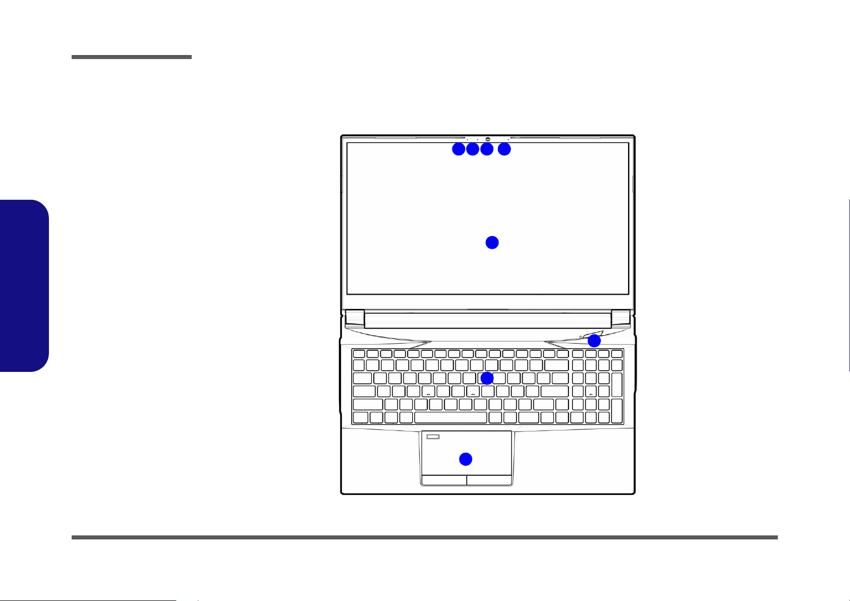
Figure 1
Top View
1. Webcam
2. *Camera LED
*When the PC
camera is in use,
the LED will be
illuminated.
3. Built-In Array
Microphone
4. Display
5. Power Button
6. Keyboard
7. Touchpad &
Buttons
2 1
7
6
4
5
33
1.Introduction
External Locator - Top View with LCD Panel Open
1 - 4 External Locator - Top View with LCD Panel Open
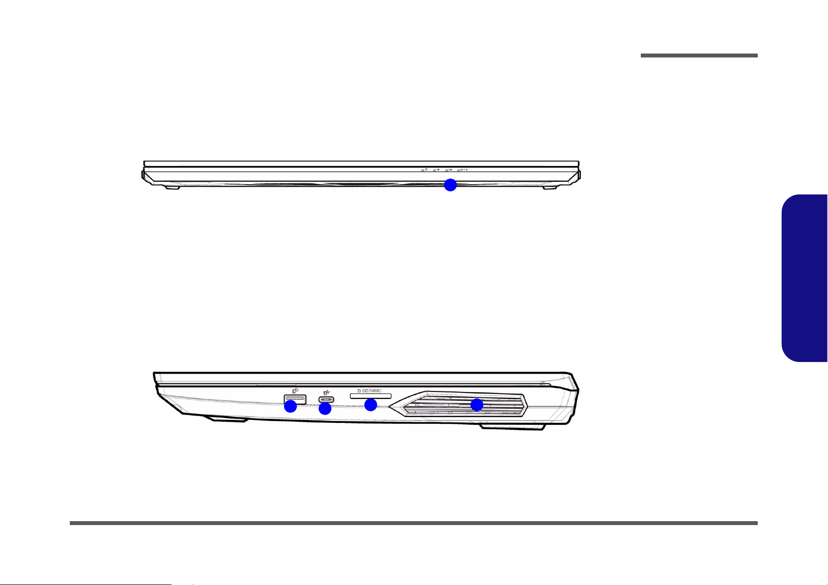
External Locator - Front & Right Side Views
Figure 2
Front View
1. LED Indicators
Figure 3
Right Side View
1. USB 3.2 Gen 2
Type-A Port
2. USB 3.2 Gen 2
Type-C Port
3. Multi-in-1 Card
Reader
4. Vent
FRONT VIEW
1
RIGHT SIDE VIEW
1
2
43
Introduction
1.Introduction
External Locator - Front & Right Side Views 1 - 5
Introduction
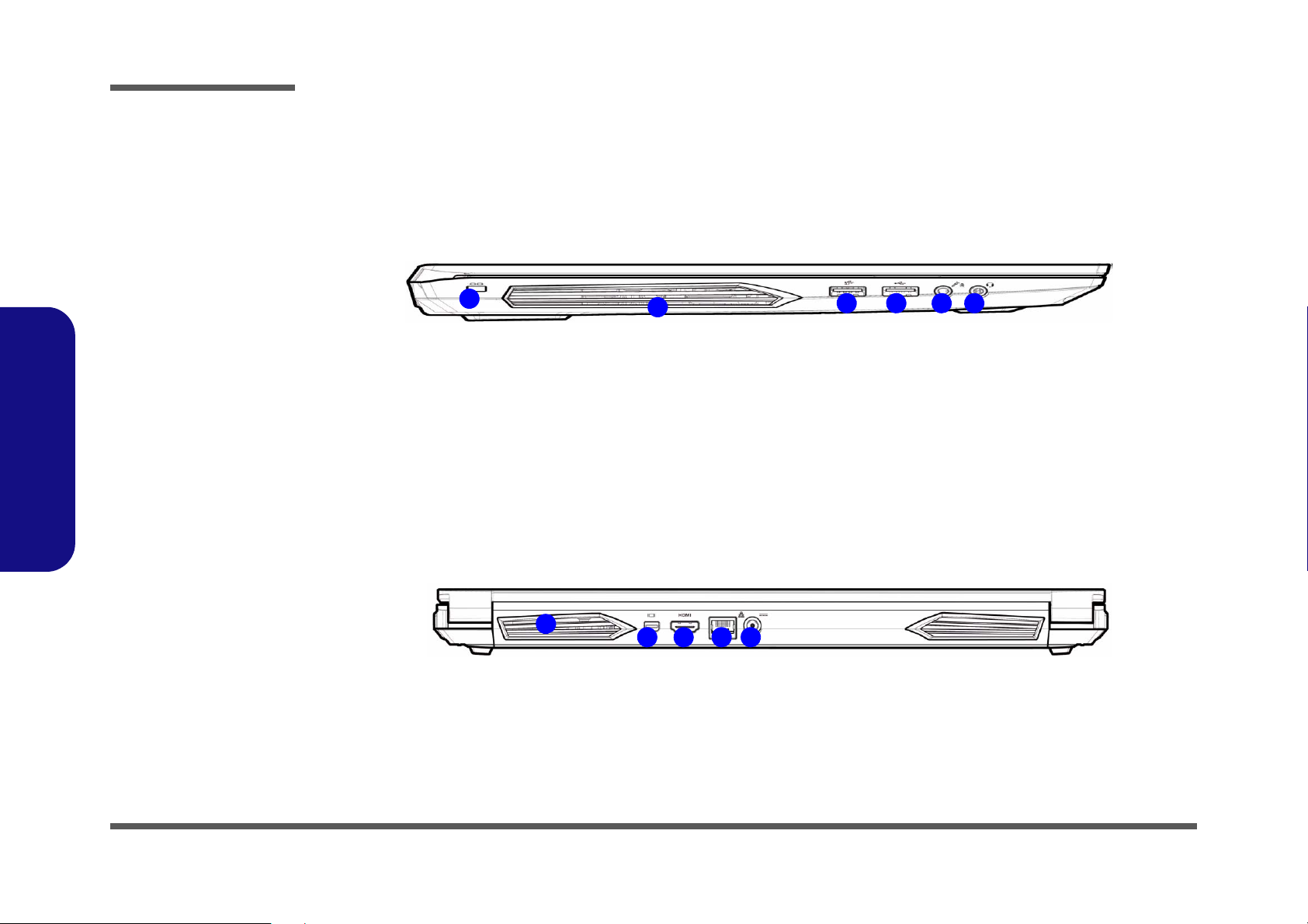
Figure 4
Left Side View
1. Security Lock Slot
2. Vent
3. USB 3.2 Gen 1
Type-A Port
4. USB 2.0 Port
5. Microphone-In
Jack
6. 2-In-1 Audio Jack
(Headphone and
Microphone)
LEFT SIDE VIEW
1
2
3 4 5 6
Figure 5
Rear View
1. Vent
2. Mini DisplayPort
1.4
3. HDMI-Out Port
4. RJ-45 LAN Jack
5. DC-In Jack
REAR VIEW
1
2 3 4 5
1.Introduction
External Locator - Left Side & Rear View
/
1 - 6 External Locator - Left Side & Rear View
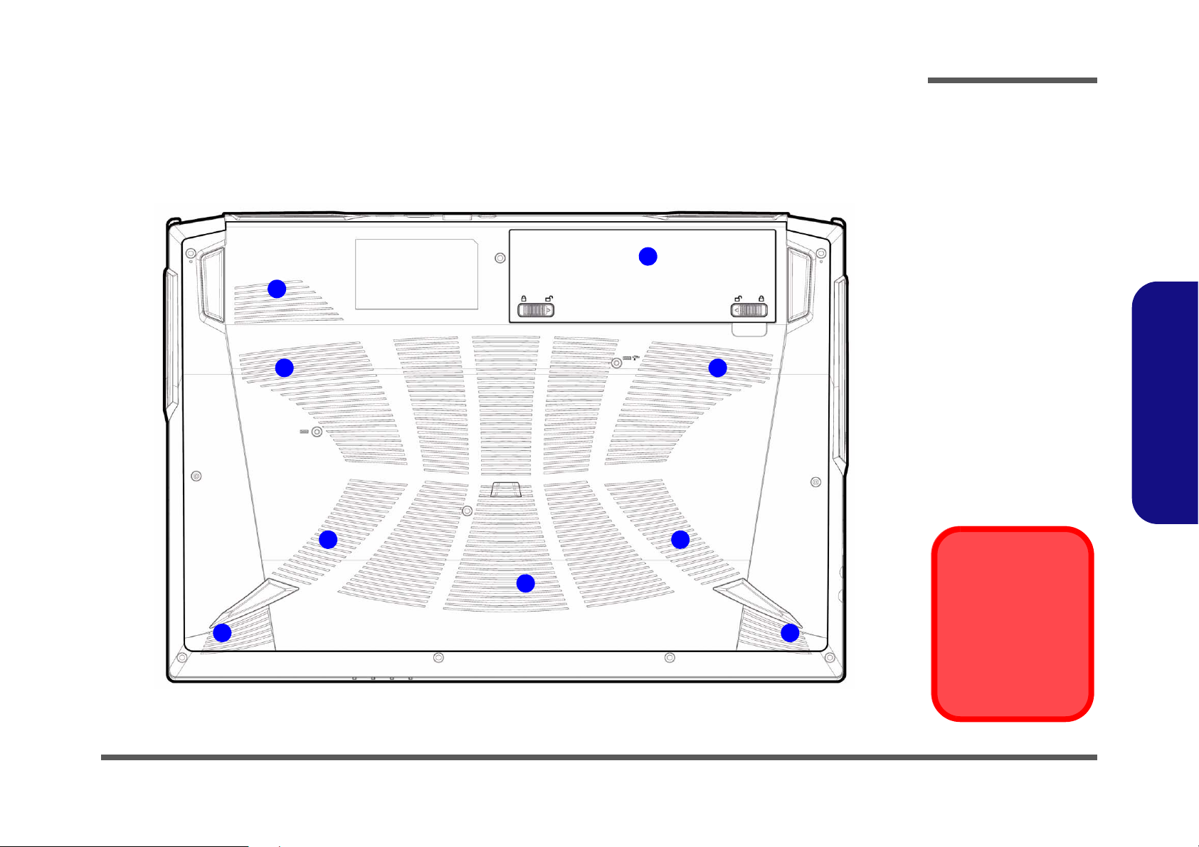
External Locator - Bottom View
Overheating
To prevent your computer from overheating, make sure nothing blocks any vent
while the computer is
in use.
2
1
3
2
3
2 2
2 2
Figure 6
Bottom View
1. Battery
2. Vent
3. Speakers
Introduction
1.Introduction
External Locator - Bottom View 1 - 7
Introduction
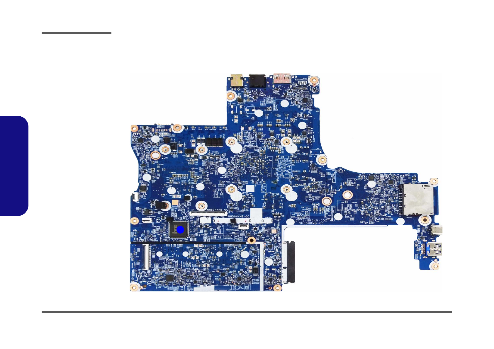
Figure 7
Mainboard Top
Key Parts
1. KBC-ITE IT5570
1
1.Introduction
Mainboard Overview - Top (Key Parts)
1 - 8 Mainboard Overview - Top (Key Parts)
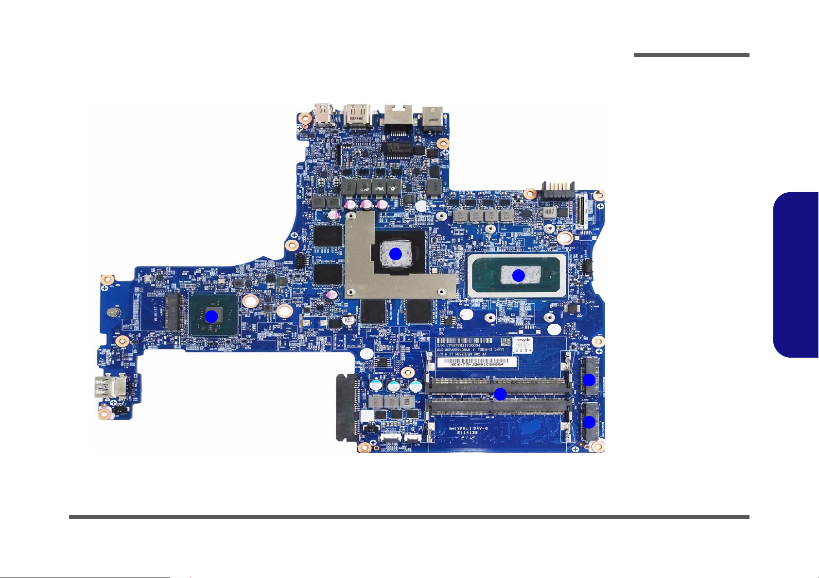
1
2
3
4
5
5
Figure 8
Mainboard Bottom
Key Parts
1. Mini-Card
Connector (WLAN
Module)
2. GPU
3. CPU
4. Memory Slots
DDR4 SO-DIMM
5. M.2 Card
Connector (SATA/
PCIE SSD)
Mainboard Overview - Bottom (Key Parts)
Introduction
1.Introduction
Mainboard Overview - Bottom (Key Parts) 1 - 9
Introduction
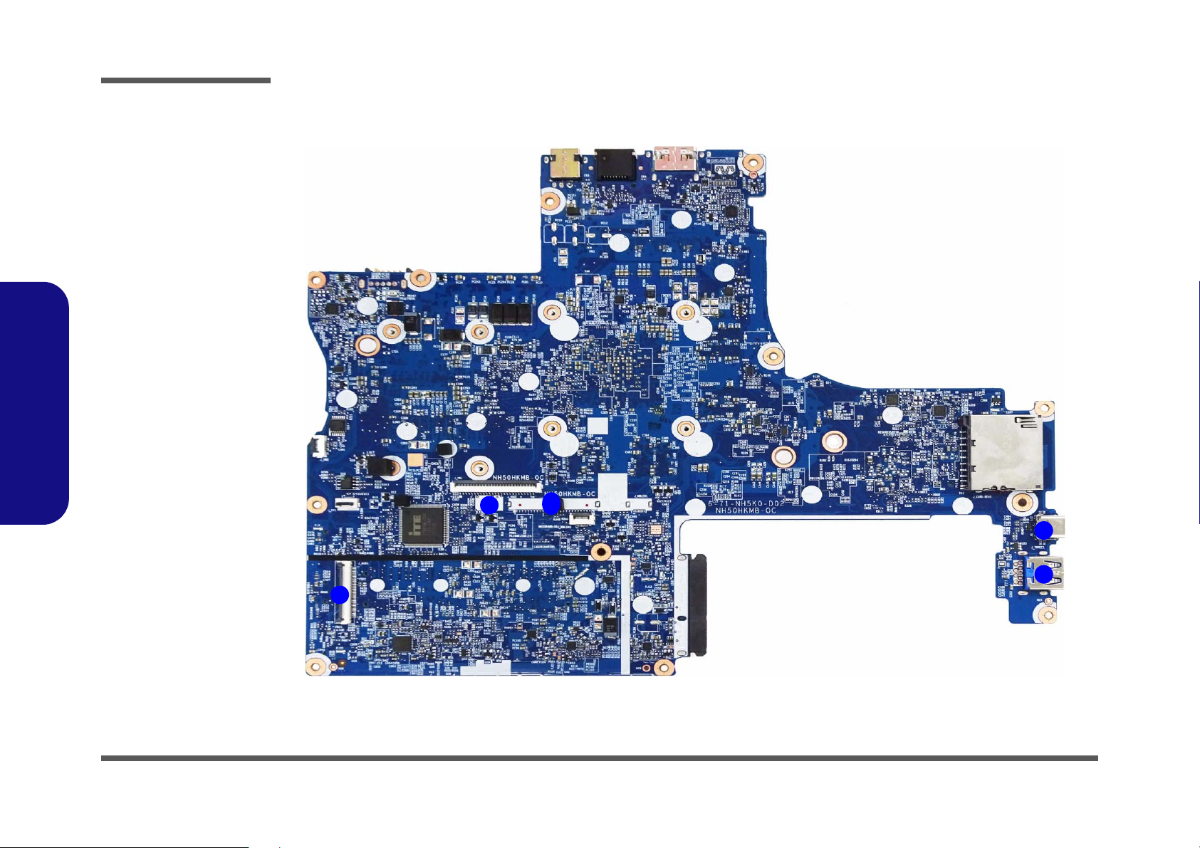
Figure 9
Mainboard Top
Connectors
1. USB Connector
2. Keyboard Cable
Connector
3. KB LED
Connector
4. USB 3.2 Gen 2
Type-C Port
5. USB 3.2 Gen 2
Type-A Port
10
5
1
2
3
4
1.Introduction
Mainboard Overview - Top (Connectors)
1 - 10 Mainboard Overview - Top (Connectors)
Mainboard Overview - Bottom (Connectors)
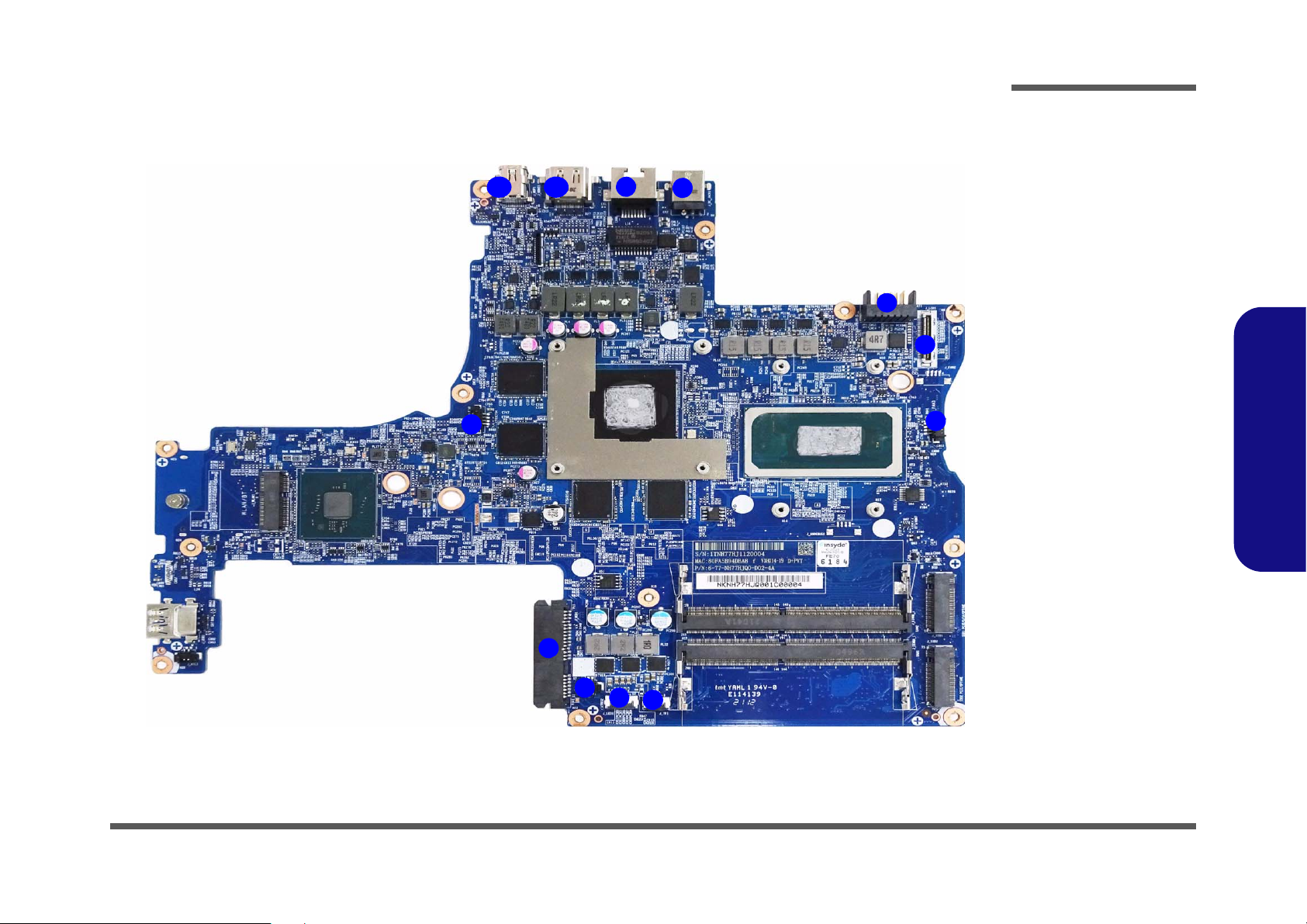
Figure 10
Mainboard Bottom
Connectors
1. Fan Connector
2. HDD Connector
3. Speaker Connector
4. LED Connector
5. Touchpad
Connector
6. LCD Connector
7. Battery Connector
8. DC-In Jack
9. RJ-45 LAN Jack
10. HDMI-Out Port
11. Mini Display Port
1.4
1
2
5
3
4
1
6
7
8
9
1011
Introduction
1.Introduction
Mainboard Overview - Bottom (Connectors) 1 - 11

1.Introduction
Introduction
1 - 12

Chapter 2: Disassembly
Disassembly
Note that for the disassembly of any key parts, the bottom case must be properly
closed before opening the upper part of the LCD to avoid any damage caused by
the nature of the structure.
Information
Warning
Disassembly
Overview
This chapter provides step-by-step instructions for disassembling the NH55HHQ / NH55HJQ / NH55HKQ /
NH58HHQ / NH58HJQ / NH58HKQ series notebook’s parts and subsystems. When it comes to reassembly, reverse
the procedures (unless otherwise indicated).
We suggest you completely review any procedure before you take the computer apart.
Procedures such as upgrading/replacing the RAM, optical device and hard disk are included in the User’s Manual but are
repeated here for your convenience.
To make the disassembly process easier each section may have a box in the page margin. Information contained under
the figure # will give a synopsis of the sequence of procedures involved in the disassembly procedure. A box with a
lists the relevant parts you will have after the disassembly process is complete. Note: The parts listed will be for the dis-
assembly procedure listed ONLY, and not any previous disassembly step(s) required. Refer to the part list for the previous disassembly procedure. The amount of screws you should be left with will be listed here also.
A box with a will also provide any possible helpful information. A box with a contains warnings.
An example of these types of boxes are shown in the sidebar.
2.Disassembly
Overview 2 - 1
Disassembly
2.Disassembly
NOTE: All disassembly procedures assume that the system is turned OFF, and disconnected from any power supply (the
battery is removed too).
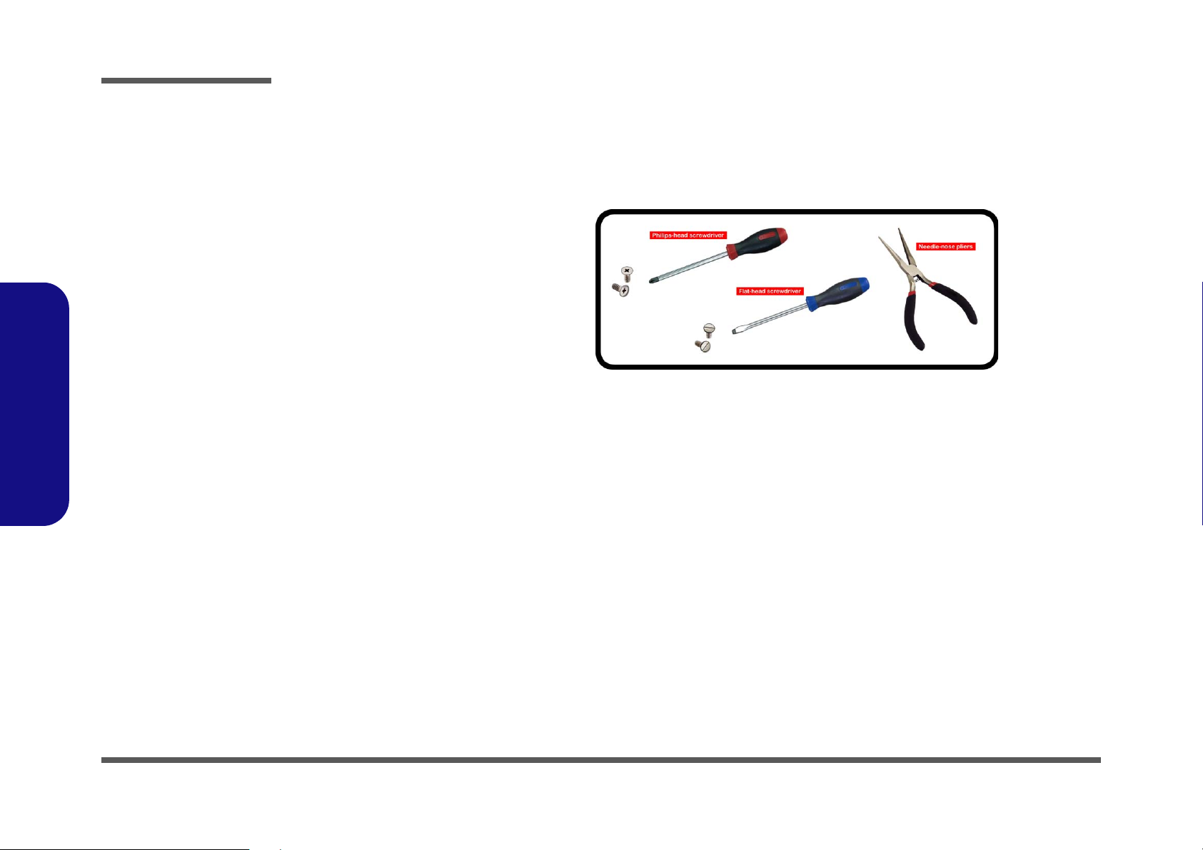
Maintenance Tools
The following tools are recommended when working on the notebook PC:
• M3 Philips-head screwdriver
• M2.5 Philips-head screwdriver (magnetized)
• M2 Philips-head screwdriver
• Small flat-head screwdriver
• Pair of needle-nose pliers
• Anti-static wrist-strap
Connections
Connections within the computer are one of four types:
Locking collar sockets for ribbon connectors To release these connectors, use a small flat-head screwdriver to
gently pry the locking collar away from its base. When replacing the connection, make sure the connector is oriented in the
same way. The pin1 side is usually not indicated.
2 - 2 Overview
Pressure sockets for multi-wire connectors To release this connector type, grasp it at its head and gently
rock it from side to side as you pull it out. Do not pull on the
wires themselves. When replacing the connection, do not try to
force it. The socket only fits one way.
Pressure sockets for ribbon connectors To release these connectors, use a small pair of needle-nose pli-
ers to gently lift the connector away from its socket. When replacing the connection, make sure the connector is oriented in
the same way. The pin1 side is usually not indicated.
Board-to-board or multi-pin sockets To separate the boards, gently rock them from side to side as
you pull them apart. If the connection is very tight, use a small
flat-head screwdriver - use just enough force to start.

Maintenance Precautions
Power Safety
Warning
Before you undertake
any upgrade procedures, make sure that
you have turned off the
power, and disconnected all peripherals
and cables (including
telephone lines and
power cord). It is advisable to also remove
your battery in order to
prevent accidentally
turning the machine
on.
The following precautions are a reminder. To avoid personal injury or damage to the computer while performing a removal and/or
replacement job, take the following precautions:
1. Don't drop it. Perform your repairs and/or upgrades on a stable surface. If the computer falls, the case and other components
could be damaged.
2. Don't overheat it. Note the proximity of any heating elements. Keep the computer out of direct sunlight.
3. Avoid interference. Note the proximity of any high capacity transformers, electric motors, and other strong magnetic fields.
These can hinder proper performance and damage components and/or data. You should also monitor the position of magnetized tools (i.e. screwdrivers).
4. Keep it dry. This is an electrical appliance. If water or any other liquid gets into it, the computer could be badly damaged.
5. Be careful with power. Avoid accidental shocks, discharges or explosions.
•Before removing or servicing any part from the computer, turn the computer off and detach any power supplies.
•When you want to unplug the power cord or any cable/wire, be sure to disconnect it by the plug head. Do not pull on the wire.
6. Peripherals – Turn off and detach any peripherals.
7. Beware of static discharge. ICs, such as the CPU and main support chips, are vulnerable to static electricity. Before han-
dling any part in the computer, discharge any static electricity inside the computer. When handling a printed circuit board, do
not use gloves or other materials which allow static electricity buildup. We suggest that you use an anti-static wrist strap
instead.
8. Beware of corrosion. As you perform your job, avoid touching any connector leads. Even the cleanest hands produce oils
which can attract corrosive elements.
9. Keep your work environment clean. Tobacco smoke, dust or other air-born particulate matter is often attracted to charged
surfaces, reducing performance.
10. Keep track of the components. When removing or replacing any part, be careful not to leave small parts, such as screws,
loose inside the computer.
Cleaning
Do not apply cleaner directly to the computer, use a soft clean cloth.
Do not use volatile (petroleum distillates) or abrasive cleaners on any part of the computer.
(For Computer Models Supplied with Light Blue Cleaning Cloth) Some computer models in this series come supplied with a
light blue cleaning cloth. To clean the computer case with this cloth follow the instructions below.
• Power off the computer and peripherals.
• Disconnect the AC/DC adapter from the computer.
• Use a little water to dampen the cloth slightly.
• Clean the computer case with the cloth.
• Dry the computer with a dry cloth, or allow it time to dry before turning on.
• Reconnect the AC/DC adapter and turn the computer on.
Disassembly
2.Disassembly
Overview 2 - 3

Disassembly
Disassembly Steps
The following table lists the disassembly steps, and on which page to find the related information. PLEASE PERFORM
THE DISASSEMBLY STEPS IN THE ORDER INDICATED.
2.Disassembly
To remove the Battery:
1. Remove the battery page 2 - 5
To remove the Keyboard:
1. Remove the keyboard page 2 - 6
To remove the HDD:
1. Remove the battery page 2 - 5
2. Remove the HDD page 2 - 7
To remove the System Memory:
1. Remove the battery page 2 - 5
2. Remove the HDD page 2 - 7
3. Remove the system memory page 2 - 9
To remove the M.2 SSD:
1. Remove the battery page 2 - 5
2. Remove the HDD page 2 - 7
3. Remove the SSD page 2 - 10
To remove the Wireless LAN Module:
1. Remove the battery page 2 - 5
2. Remove the HDD page 2 - 7
3. Remove the WLAN page 2 - 11
To remove the CCD Module:
1. Remove the battery page 2 - 5
2. Remove the HDD page 2 - 7
3. Remove the CCD module page 2 - 13
2 - 4 Disassembly Steps
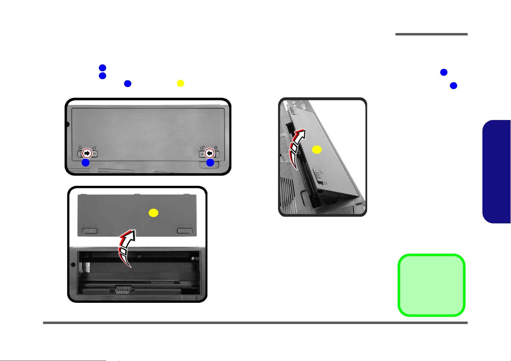
Removing the Battery
122
3
Figure 1
Battery Removal
a. Slide the latch in the
direction of the arrow.
and slide the latch in
the direction of the arrow.
b. Lift the battery.
c. Remove the battery.
1
2
1
a.
b.
3
c.
3
2
3. Battery
1. Turn the computer off, and turn it over.
2. Slide the latch in the direction of the arrow (Figure 1a).
3. Slide the latch in the direction of the arrow.
4. While holding the latch , lift the battery (Figure 1b) out of the compartment (Figure 1c
Disassembly
).
2.Disassembly
Removing the Battery 2 - 5
Disassembly
123456778
6
a. b.
1
2
c.
6
7
8
6
3
4
8
5
7
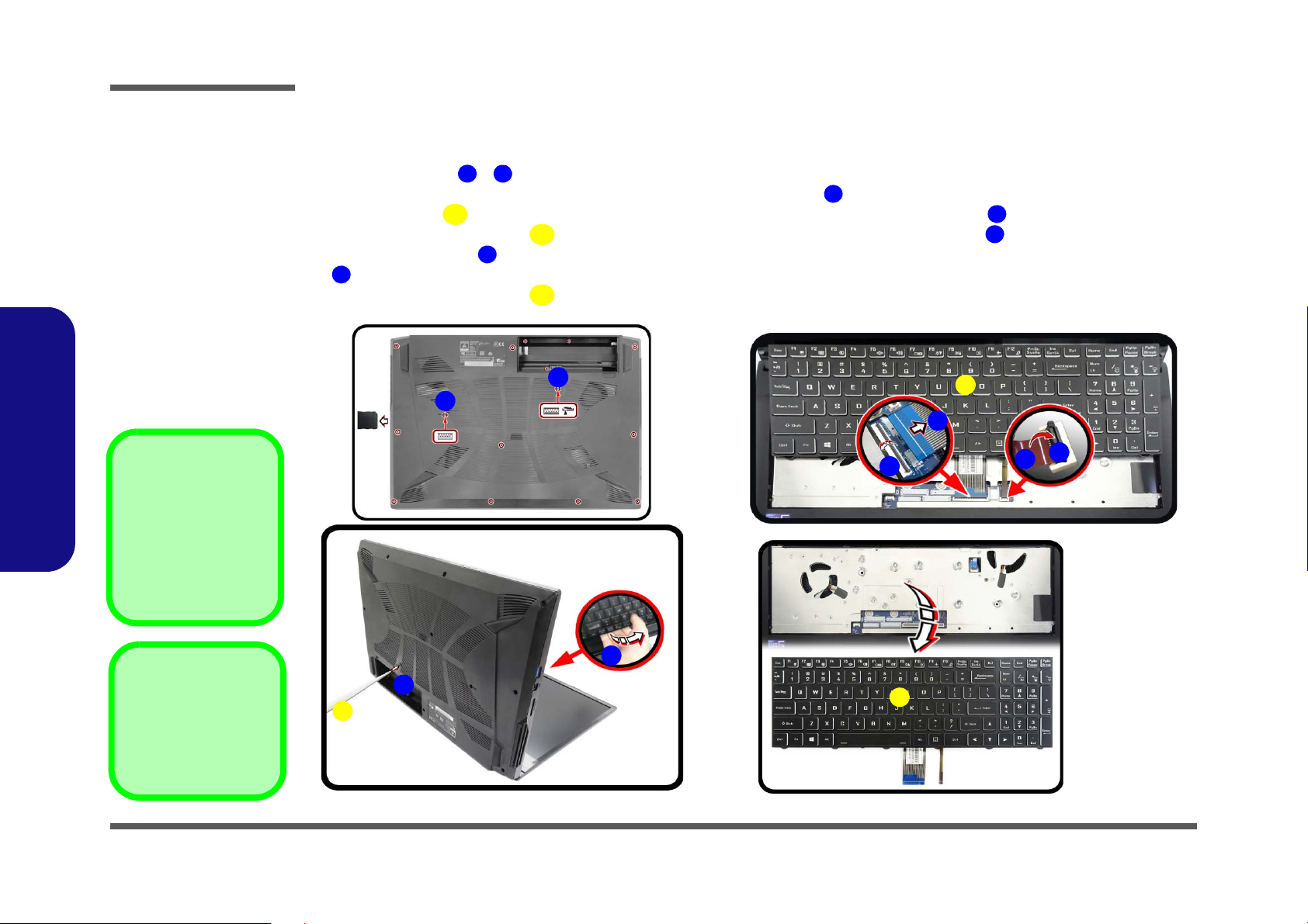
4. Eject Stick
6. Keyboard
•2 Screws
Figure 2
Keyboard Removal
a. Remove the screws from
the bottom of the computer and then eject the
keyboard using a special
eject stick to push the
keyboard out while releasing the keyboard as
shown.
b. Lift the keyboard up and
disconnect the keyboard
ribbon cable from the
locking collar socket.
c. Remove the keyboard.
Re-inserting the Key-
board
When re-inserting the
keyboard firstly, align the
keyboard tabs at the bottom of the keyboard with
the slots in the case.
Removing the Keyboard
1. Turn off the computer, turn it over.
2. Remove screws
3. Open it up with the LCD on a flat surface before pressing at point
cial eject stick to do this) while releasing the keyboard in the direction of the arrow
4. Carefully lift the keyboard
board ribbon cable from the locking collar socket by using a flat-head screwdriver to pry the locking collar pins
away from the base (Figure 2b).
5. Carefully lift the keyboard off the computer (Figure 2c).
2.Disassembly
- from the bottom of the computer.
up, being careful not to bend the keyboard ribbon cable . Disconnect the key-
to release the keyboard module (use the spe-
as shown (Figure 2a).
2 - 6 Removing the Keyboard
 Loading...