

Clevo N850EZ, N870EZ, N871EZ User guide


Contents
About this Concise User Guide ......................................................................1
System Startup ................................................................................................ 4
Intel® Optane™ Setup ...................................................................................5
System Map: Front View with LCD Panel Open (Model A) .........................8
System Map: Front View with LCD Panel Open (Model B) .........................9
System Map: Front View with LCD Panel Open (Model C) .......................10
LED Indicators ............................................................................................. 11
Keyboard ......................................................................................................12
System Map: Front, Left, Right & Rear Views (Model A) .......................... 14
System Map: Front, Left, Right & Rear Views (Model B) ..........................15
System Map: Front, Left, Right & Rear Views (Model C) ..........................16
System Map: Bottom Views .........................................................................17
Control Center (Design I) .............................................................................18
Control Center (Design II) ............................................................................21
Flexikey® Application .................................................................................24
Windows 10 Start Menu, Context Menu, Taskbar, Control Panel and
Settings ......................................................................................................... 28
Video Features .............................................................................................. 29
Audio Features ..............................................................................................31
Power Options ..............................................................................................32
Driver Installation .........................................................................................33
TPM (Option) ............................................................................................... 34
4G Module (Option) .....................................................................................35
Troubleshooting ............................................................................................ 36
Specifications ................................................................................................ 37
Inhalt
Über das Ausführliche Benutzerhandbuch ................................................... 41
Schnellstart ................................................................................................... 44
Intel® Optane™ ...........................................................................................45
Systemübersicht: Ansicht von vorne mit geöffnetem LCD-Bildschirm
(Modell A) .................................................................................................... 48
Systemübersicht: Ansicht von vorne mit geöffnetem LCD-Bildschirm
(Modell B) ....................................................................................................49
Systemübersicht: Ansicht von vorne mit geöffnetem LCD-Bildschirm
(Modell C) ....................................................................................................50
LED-Anzeigen .............................................................................................. 51
Tastatur ......................................................................................................... 52
Systemübersicht: Ansicht von vorne, links, rechts und hinten
(Modell A) .................................................................................................... 54
Systemübersicht: Ansicht von vorne, links, rechts und hinten
(Modell B) ....................................................................................................55
Systemübersicht: Ansicht von vorne, links, rechts und hinten
(Modell C) ....................................................................................................56
Systemübersicht: Ansichten von unten ........................................................ 57
Control Center (Design I) ............................................................................. 58
Control Center (Design II) ............................................................................ 61
Flexikey® Anwendung ................................................................................ 64
Start-Menü, Kontextmenü, Taskleiste, Systemsteuerung und Einstellungen
von Windows 10 ........................................................................................... 68
Grafikfunktionen .......................................................................................... 69
Energieoptionen ............................................................................................ 72
Installation der Treiber ................................................................................. 73
TPM (Option) ............................................................................................... 74
4G-Modul (Option) ...................................................................................... 75
Fehlerbehebung ............................................................................................ 76
Technische Daten ......................................................................................... 77
Sommaire
A propos de ce Guide Utilisateur Concis ..................................................... 81
Guide de démarrage rapide ........................................................................... 84
Intel® Optane™ ........................................................................................... 85
Carte du système: Vue de face avec l’écran LCD ouvert (Modèle A) ........88
Carte du système: Vue de face avec l’écran LCD ouvert (Modèle B) ........89
Carte du système: Vue de face avec l’écran LCD ouvert (Modèle C) .........90
Indicateurs LED ............................................................................................ 91
Clavier .......................................................................................................... 92
Carte du système: Vues de face, gauche, droite et arrière (Modèle A) ........ 94
Carte du système: Vues de face, gauche, droite et arrière (Modèle B) .......95
Carte du système: Vues de face, gauche, droite et arrière (Modèle C) ........96
Carte du système: Vues de dessous ............................................................. 97
Control Center (Design I) ............................................................................. 98
Control Center (Design II) .......................................................................... 101

Application Flexikey® ............................................................................... 104
Menu Démarrer, Menu contextuel, Barre des tâches, Panneau de
Configuration et Paramètres de Windows 10 .............................................108
Caractéristiques vidéo ................................................................................. 109
Caractéristiques audio ................................................................................. 111
Options d’alimentation ............................................................................... 112
Installation du pilote ................................................................................... 113
TPM (Option) ............................................................................................. 114
Module 4G (Option) ................................................................................... 115
Dépannage .................................................................................................. 116
Spécifications .............................................................................................. 117
Contenidos
Acerca de esta Guía del Usuario Concisa ................................................... 121
Guía rápida para empezar ...........................................................................124
Intel® Optane™ .........................................................................................125
Diferencias de modelos ..............................................................................127
Mapa del sistema: Vista frontal con panel LCD abierto (Modelo A) ........128
Mapa del sistema: Vista frontal con panel LCD abierto (Modelo B) ......... 129
Mapa del sistema: Vista frontal con panel LCD abierto (Modelo C) ......... 130
Indicadores LED .........................................................................................131
Teclado ....................................................................................................... 132
Mapa del sistema: Vistas frontal, izquierda, derecha y posterior
(Modelo A) ................................................................................................. 134
Mapa del sistema: Vistas frontal, izquierda, derecha y posterior
(Modelo B) .................................................................................................135
Mapa del sistema: Vistas frontal, izquierda, derecha y posterior
(Modelo C) .................................................................................................136
Mapa del sistema: Vistas inferiores ........................................................... 137
Control Center (Diseño I) ...........................................................................138
Control Center (Diseño Il) .......................................................................... 141
Aplicación Flexikey® ................................................................................. 144
Menú Inicio, Menú contextual, Barra de tareas, Panel de Control y
Configuración de Windows 10 ................................................................... 148
Parámetros de vídeo ....................................................................................149
Características de audio .............................................................................. 151
Opciones de energía .................................................................................... 152
Instalación de controladores ....................................................................... 153
TPM (Opción) ............................................................................................ 154
Módulo 4G (Opción) .................................................................................. 155
Solución de problemas ............................................................................... 156
Especificaciones ......................................................................................... 157
Sommario
Informazioni su questa guida rapida ...........................................................161
Guida di avvio rapido ................................................................................. 164
Intel® Optane™ ......................................................................................... 165
Descrizione del sistema: Vista anteriore con pannello LCD aperto
(Modello A) ............................................................................................... 168
Descrizione del sistema: Vista anteriore con pannello LCD aperto
(Modello B) ...............................................................................................169
Descrizione del sistema: Vista anteriore con pannello LCD aperto
(Modello C) ................................................................................................ 170
Indicatori LED ............................................................................................ 171
Tastiera ....................................................................................................... 172
Descrizione del sistema: Vista anteriore, sinistra, destra e posteriore
(Modello A) ................................................................................................ 174
Descrizione del sistema: Vista anteriore, sinistra, destra e posteriore
(Modello B) ................................................................................................ 175
Descrizione del sistema: Vista anteriore, sinistra, destra e posteriore
(Modello C) ................................................................................................ 176
Descrizione del sistema: Vista inferiore ..................................................... 177
Control Center (Design I) ........................................................................... 178
Control Center (Design II) .......................................................................... 181
Applicazione Flexikey® ............................................................................. 184
Menu Start, Menu contestuale, Barra delle applicazioni, Pannello di
controllo e Impostazioni di Windows 10 .................................................... 188
Funzioni video ............................................................................................ 189
Funzionalità audio ...................................................................................... 191
Opzioni risparmio energia .......................................................................... 192
Installazione driver ..................................................................................... 193
TPM (Opzione) ........................................................................................... 194
Modulo 4G (Opzione) ................................................................................ 195
Risoluzione dei problemi ............................................................................ 196
Specifiche tecniche ..................................................................................... 197

III

IV

About this Concise User Guide
FCC Statement
This device complies with Part
15 of the FCC Rules. Operation
is subject to the following two
conditions:
1. This device may not cause
harmful interference.
2. This device must accept any
interference received, including interference that may
cause undesired operation.
This quick guide is a brief introduction to getting your system started. This is a supplement, and not a substitute for the
expanded English language User’s Manual in Adobe Acrobat format on the Device Drivers & Utilities + User’s Manual
disc supplied with your computer. This disc also contains the drivers and utilities necessary for the proper operation of
the computer (Note: The company reserves the right to revise this publication or to change its contents without notice).
Some or all of the computer’s features may already have been setup. If they aren’t, or you are planning to re-configure
(or re-install) portions of the system, refer to the expanded User’s Manual. The Device Drivers & Utilities + User’s
Manual disc does not contain an operating system.
Regulatory and Safety Information
Please pay careful attention to the full regulatory notices and safety information contained in the expanded User’s Manual on the Device Drivers & Utilities + User’s Manual disc.
©
May 2018
Trademarks
Intel is a trademark/registered trademark of Intel Corporation.
Windows is a registered trademark of Microsoft Corporation.
English
1

Instructions for Care and Operation
The computer is quite rugged, but it can be damaged. To prevent this, follow these suggestions:
• Don’t drop it, or expose it to shock. If the computer falls, the
case and the components could be damaged.
• Keep it dry, and don’t overheat it. Keep the computer and
power supply away from any kind of heating element. This is an
electrical appliance. If water or any other liquid gets into it, the
English
computer could be badly damaged.
• Avoid interference. Keep the computer away from high capacity
transformers, electric motors, and other strong magnetic fields.
These can hinder proper performance and damage your data.
• Follow the proper working procedures for the computer. Shut
the computer down properly and don’t forget to save your work.
Remember to periodically save your data as data may be lost.
Servicing
Do not attempt to service the computer yourself. Doing so may
violate your warranty and expose you and the computer to
electric shock. Refer all servicing to authorized service personnel. Unplug the computer from the power supply. Then refer
servicing to qualified service personnel under any of the following conditions:
• When the power cord or AC/DC adapter is damaged or frayed.
• If the computer has been exposed to any liquids.
• If the computer does not work normally when you follow the
operating instructions.
• If the computer has been dropped or damaged (do not touch the
poisonous liquid if the LCD panel breaks).
• If there is an unusual odor, heat or smoke coming from your computer.
Safety Information
• Only use an AC/DC adapter approved for use with this computer.
• Use only the power cord and batteries indicated in this manual.
Do not dispose of batteries in a fire. They may explode. Check
with local codes for possible special disposal instructions.
• Do not continue to use a battery that has been dropped, or that
appears damaged (e.g. bent or twisted) in any way. Even if the
computer continues to work with a damaged battery in place, it
may cause circuit damage, which may possibly result in fire.
• Make sure that your computer is completely powered off before
putting it into a travel bag (or any such container).
• Before cleaning the computer, make sure it is disconnected from
any external power supplies, peripherals and cables. It is advisable to also remove your battery in order to prevent accidentally
turning the machine on.
• Use a soft clean cloth to clean the computer, but do not apply
cleaner directly to the computer. Do not use volatile (petroleum
distillates) or abrasive cleaners on any part of the computer.
• Do not try to repair a battery pack. Refer any battery pack repair
or replacement to your service representative or qualified service
personnel.
• Note that in computer’s featuring a raised LCD electro-plated
logo, the logo is covered by a protective adhesive. Due to general
wear and tear, this adhesive may deteriorate over time and the
exposed logo may develop sharp edges. Be careful when handling
the computer in this case, and avoid touching the raised LCD
electro-plated logo. Avoid placing any other items in the carrying
bag which may rub against the top of the computer during transport. If any such wear and tear develops contact your service center.
2

Polymer Battery Precautions
Battery Disposal & Caution
The product that you have purchased contains a rechargeable battery. The battery is recyclable. At the end of its useful life, under various state and local laws, it may be illegal
to dispose of this battery into the municipal waste stream.
Check with your local solid waste officials for details in your
area for recycling options or proper disposal.
Danger of explosion if battery is incorrectly replaced. Replace only with the same or equivalent type recommended
by the manufacturer. Discard used battery according to the
manufacturer’s instructions.
Note the following information which is specific to polymer
batteries only, and where applicable, this overrides the general
battery precaution information.
• Polymer batteries may experience a slight expansion or swelling,
however this is part of the battery’s safety mechanism and is not a
cause for concern.
• Use proper handling procedures when using polymer batteries.
Do not use polymer batteries in high ambient temperature environments, and do not store unused batteries for extended periods.
English
3
System Startup
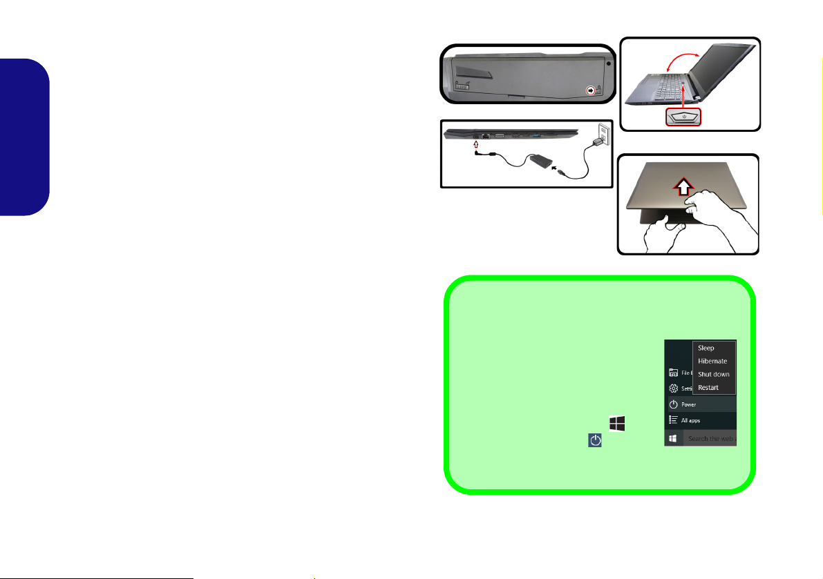
Figure 1
Opening the Lid/LCD/
Computer with AC/DC
Adapter Plugged-In
Shut Down
Note that you should always shut
your computer down by choosing the
Shut down command in Windows
(see below). This will help prevent
hard disk or system problems.
1. Click the Start Menu icon .
2. Click the Power item .
3. Choose Shut Down from the
menu.
130°
1. Remove all packing materials.
2. Place the computer on a stable surface.
3. Insert the battery and make sure it is locked in position.
4. Securely attach any peripherals you want to use with the computer
(e.g. keyboard and mouse) to their ports.
5. When first setting up the computer use the following procedure
English
(as to safeguard the computer during shipping, the battery will be
locked to not power the system until first connected to the AC/DC
adapter and initially set up as below):
• Attach the AC/DC adapter cord to the DC-In jack on the left of the
computer, then plug the AC power cord into an outlet, and connect
the AC power cord to the AC/DC adapter and leave it there for 6
seconds or longer.
• Remove the adapter cord from the computer’s DC-In jack, and then
plug it back in again; the battery will now be unlocked.
6. Use one hand to raise the
exceed 130 degrees); use the other hand (as illustrated in Figure 1) to
support the base of the computer (Note: Never lift the computer by the
lid/LCD).
7. Press the power button to turn the computer “on”.
lid/LCD to a comfortable viewing angle
(do not
System Software
Your computer may already come with system software pre-installed. Where this is not the case, or where you are re-configuring your computer for a different system, you will find this
manual refers to Microsoft Windows 10.
Intel® Optane™ Support
You need to setup Intel® Optane™ before installing your Windows 10 operating system (see Intel® Optane™ Setup
on page 5).
4

Intel® Optane™ Setup
Intel® Optane™ is a combination of a compatible memory device and Intel Rapid Storage Technology soft-
ware. This combination is designed to speed up your
system performance by caching boot data, executables,
frequently accessed data and system page files to a non
volatile, low latency Intel® Optane™ SSD.
Contact your distributor or supplier to see if your system
supports this technology.
If you are reinstalling a system that has previously been
setup in Intel RST Premium mode, make sure you have
cleared the Intel Optane Memory (see Clearing Intel®
Optane™ on page 6).
Intel® Optane™ Setup Procedure
You need to setup Intel® Optane™ before installing your
Windows 10 operating system, and you will need to prepare the following in order to do so.
• The Microsoft Windows 10 OS DVD.
• An attached external DVD drive.
• An Intel® Optane™ SSD installed in your system.
• The Device Drivers & Utilities + User’s Manual disc.
1. Start-up your notebook computer and press F2 to enter the
BIOS.
2. Go to the Boot menu, select UEFI Setting and press Enter.
3. Set UEFI Boot to “Enabled”.
4. Press Esc to exit the menu and go to the Main menu.
5. Select OffBoard NVMe Controller Configuration and press
Enter to check that an Intel® Optane™ SSD is present.
6. Press Esc to exit the menu and go to the Advanced menu.
7. Select SATA Mode, press Enter and select “Intel RST
Premium...”.
8. Press F4 and <Yes> to “Save Changes and Reset”.
9. As the computer restarts press F2 to enter the BIOS again.
10. Press F4 and <Yes> to “Save Changes and Reset”, however
ensure that the condition in the bulleted point below is met
before doing so.
• Make sure the Windows 10 OS DVD is in the attached DVD
drive, as the computer starts up it will automatically boot from
the Windows 10 OS DVD (you will be prompted to press a key
to boot from the DVD).
11. Click Next > Install Now to continue installing the operating
system as normal (see your Windows documentation if you
need help on installing the Windows OS).
12. Select Custom: Install Windows only (advanced).
13. It is recommended that you select and then delete existing
partitions.
14. Click New to create a partition for Windows.
15. It is very important to make sure that when you create the
partition, leave at least a minimum of unallocated space of 5MB.
16. Follow the on-screen instructions to install the Windows 10
operating system.
17. Install the Windows drivers. Make sure you install the Intel®
Rapid Storage Technology (IRST) driver.
18. Run the Intel® Rapid Storage Technology application.
English
5
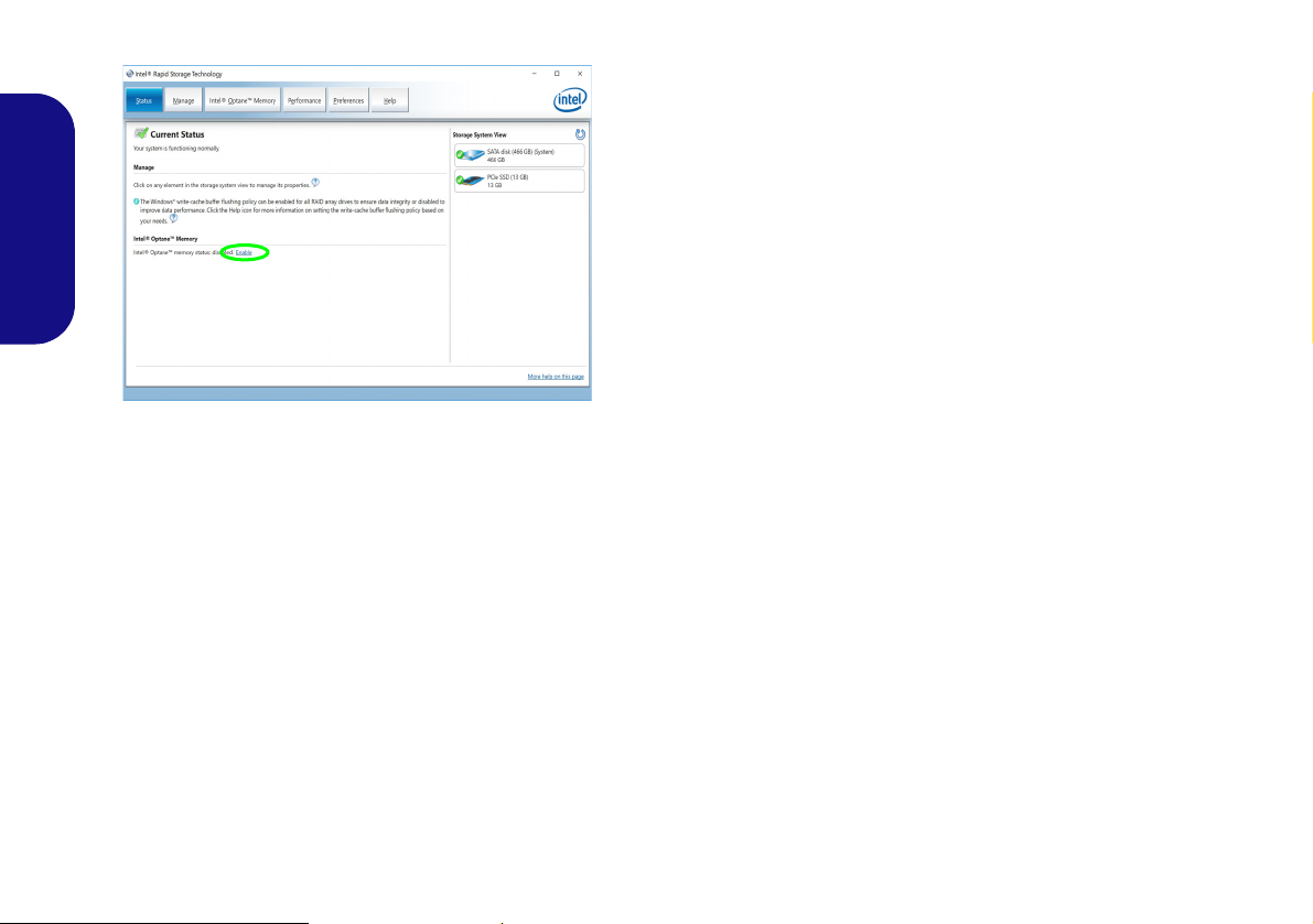
19. Click Enable.
Figure 2 - Intel® Rapid Storage Technology - Status
English
20. The system will pop-up a message and ask you to select a
compatible fast drive (in this case there should only be one
option).
21. You will need to restart the computer after enabling Optane, and
make sure the system is powered by the powered AC/DC
adapter, and not by battery only.
22. Click Yes to begin the process (this may take some time).
23. After the process has been completed restart the computer.
Clearing Intel® Optane™
If you wish to clear an existing Intel® Optane™ setup
then follow the procedure below to do so. However back-
up up any necessary files and data before clearing an
Intel® Optane™ setup, as doing so will result in the loss
of all data on the volumes.
1. Make sure that Intel® Optane™ is enabled in the Intel® Rapid
Storage Technology application.
2. Start-up your computer and press F2 to enter the BIOS.
3. Go to Intel(R) Rapid Storage Technology (in the Advanced
menu) and press Enter.
4. Select Intel Optane, **** (listed under Optane Volume:) and
press Enter.
5. Select “Deconcatentate” and press Enter.
6. Select Yes from the “Are you sure you want to perform
deconcatentation” option.
7. Select “Start deconcatentation” and press Enter.
8. The system will return to the standard Intel(R) Rapid Storage
Technology menu when complete.
9. You should then select the appropriate SATA Mode for your
system and reinstall the OS.
6

Model Differences
This notebook series includes three different models that vary slightly in design style, color and general appearance.
Not all the model variants, colors, configurations, buttons etc., are pictured in this manual. Note that though your computer may look slightly different from that pictured throughout this manual, all ports, jacks (other than those indicated
below and in specification) and general functions are the same for all the design styles (see Specifications for further
details).
Model A Model B Model C
Feature
Design I Design II Design I Design I Design II
Intel® Integrated
Video Adapter
GPU and
NVIDIA® Discrete
GPU
Intel® Integrated
GPU
Intel® Integrated GPU and NVIDIA®
Discrete GPU
Intel® Integrated
GPU
English
Display
4G Module
Support for Sound
Blaster Cinema 5
15.6" (39.62cm)
FHD
Yes No Yes No
15.6" (39.62cm)
HD/FHD
Option No
Table 1 - Model Differences
15.6" (39.62cm)
FHD
17.3" (43.94cm) HD+/FHD
7
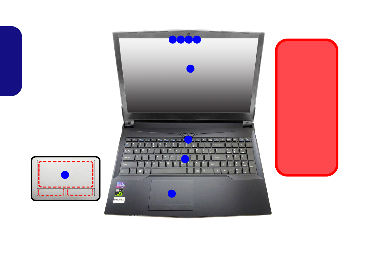
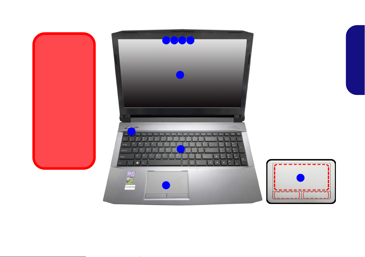
System Map: Front View with LCD Panel Open (Model A)
Figure 3
Front View with LCD Panel
Open (Model A)
1. PC Camera
2. *PC Camera LED
*When the PC camera is in
use, the LED will be
illuminated.
3. Built-In Array Microphone
4. LCD
5. Power Button
6. Keyboard
7. Touchpad & Buttons
5
7
6
2 13
4
Wireless Device
Operation Aboard
Aircraft
The use of any portable electronic
transmission devices aboard aircraft is
usually prohibited.
Make sure the
WLAN, Bluetooth &
4G module(s) are
OFF if you are using
the computer aboard
aircraft by putting the
system in to Airplane
Mode.
3
Note that the Touchpad and
Buttons valid operational
area is that indicated within
the red dotted lines.
7
English
8
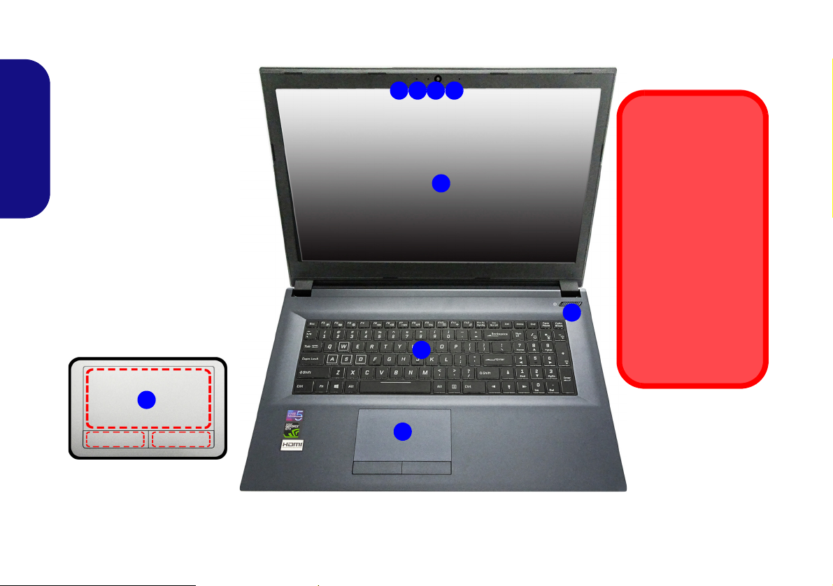
System Map: Front View with LCD Panel Open (Model B)
Note that the Touchpad and
Buttons valid operational
area is that indicated within
the red dotted lines.
Figure 4
Front View with LCD Panel
Open (Model B)
1. PC Camera
2. *PC Camera LED
*When the PC camera is
in use, the LED will be
illuminated.
3. Built-In Array Microphone
4. LCD
5. Power Button
6. Keyboard
7. Touchpad & Buttons
5
7
6
2 13
4
7
3
Wireless Device
Operation Aboard
Aircraft
The use of any portable electronic
transmission devices aboard aircraft is
usually prohibited.
Make sure the
WLAN, Bluetooth &
4G module(s) are
OFF if you are using
the computer aboard
aircraft by putting the
system in to Airplane
Mode.
English
9
System Map: Front View with LCD Panel Open (Model C)
Figure 5
Front View with LCD Panel
Open (Model A)
1. PC Camera
2. *PC Camera LED
*When the PC camera is in
use, the LED will be
illuminated.
3. Built-In Array Microphone
4. LCD
5. Power Button
6. Keyboard
7. Touchpad & Buttons
5
7
6
2 13
4
Wireless Device
Operation Aboard
Aircraft
The use of any portable electronic transmission devices aboard
aircraft is usually prohibited.
Make sure the WLAN
and Bluetooth module(s) are OFF if you
are using the computer
aboard aircraft by putting the system in to
Airplane Mode.
3
Note that the Touchpad and
Buttons valid operational
area is that indicated within
the red dotted lines.
7
English
10
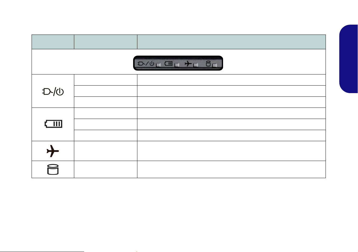
LED Indicators
The LED indicators on the computer display helpful information about the current status of the computer.
Icon Color Description
Orange The AC/DC Adapter is Plugged In
Green The Computer is On
Blinking Green The Computer is in Sleep Mode
Orange The Battery is Charging
Green The Battery is Fully Charged
Blinking Orange The Battery Has Reached Critically Low Power Status
Green Airplane Mode is ON (the WLAN, Bluetooth & 4G Modules are OFF)
Green The Hard Diske is in use
Table 2 - LED Indicators
English
11
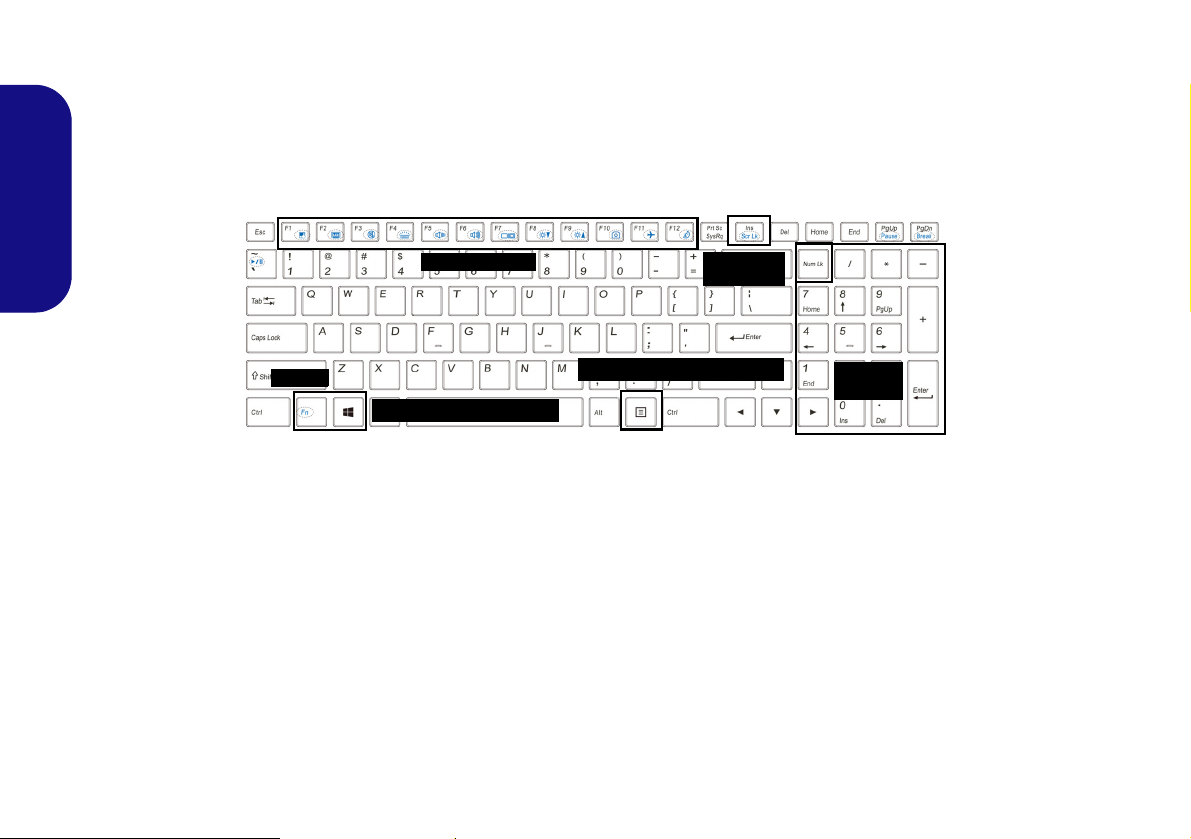
Keyboard
Function Keys
Num Lk &
Scr Lk
Numeric
Keypad
Fn Key
Windows Logo Key
Menu/Application Key
The keyboard has a numeric keypad for easy numeric data input. Pressing Num Lk turns on/off the numeric keypad.
It also features function keys to allow you to change operational features instantly.
(Illuminated keyboard - Optional) The keyboard illumination level may be adjusted, or turned off/on, by using the
Fn + F4 keys.
English
Figure 6 - Keyboard
12
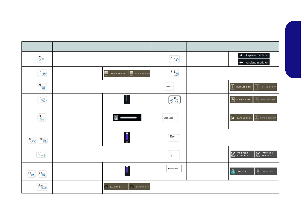
Function Keys & Visual Indicators
The function keys (F1 - F12 etc.) will act as hot keys when pressed while the Fn key is held down. In addition to the
basic function key combinations, some visual indicators are available when the Control Center driver is installed (after
restart a control panel will pop-up to allow you to select the type of keyboard for your system).
Keys Function/Visual Indicators Keys Function/Visual Indicators
English
Fn +
Fn +
Fn +
Fn +
Fn +
Fn +
Fn +
Fn +
Fn +
Play/Pause (in Audio/Video Programs)
Touchpad Toggle
Turn LCD Backlight Off
(Press a key to or use Touchpad to turn on)
Mute Toggle
Toggle Keyboard Illumi-
nation/Adjust Brightness
Level (For White-LED
Keyboards)
Volume Decrease/
Increase
Change Display Configuration (see page 30)
Brightness Decrease/
Increase
PC Camera Power
Toggle
Fn +
Fn +
Fn +
Fn +
Fn +
Fn +
(Design I Only)
Airplane Mode Tog-
gle
Number Lock Toggle
Scroll Lock Toggle
Caps Lock Toggle
Control Center Toggle (see page 18)
Fan Automatic Con-
trol/ Full Power
Disable/Enable
Flexikey® (see page
24)
Sleep Toggle
Table 3 - Function Keys & Visual Indicators
13
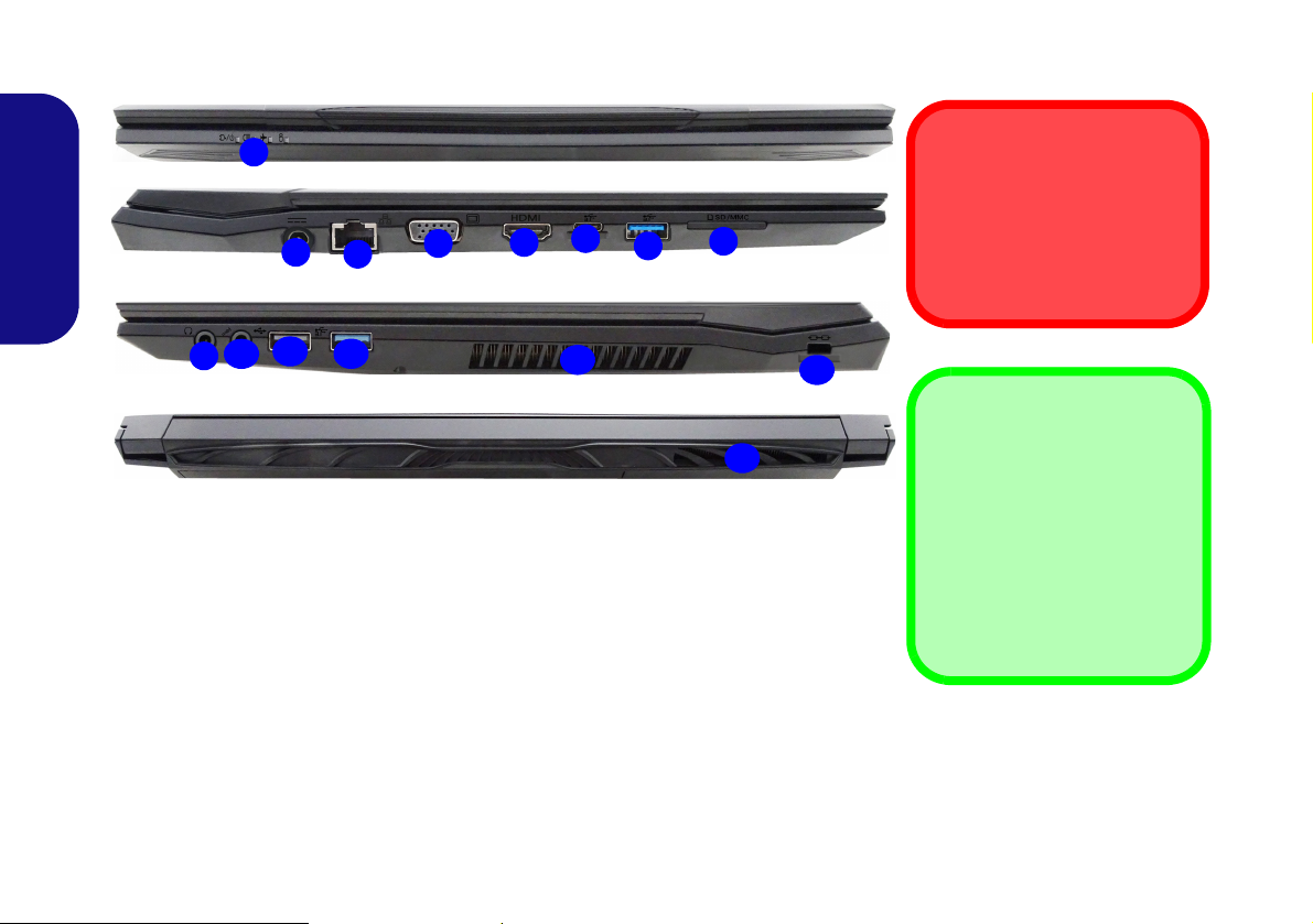
System Map: Front, Left, Right & Rear Views (Model A)
Figure 7 - Front, Left, Right & Rear Views (Model A)
1. LED Indicators
2. DC-In Jack
3. RJ-45 LAN Jack
4. External Monitor Port
5. HDMI-Out Port
6. USB 3.1 Gen 2 Type-C Port
7. USB 3.1 Gen 2 Type-A Port
8. Multi-in-1 Card Reader
9. Headphone-Out Jack
10. Microphone-In Jack
11. USB 2.0 Port
12. USB 3.0 (USB 3.1 Gen 1)
Type-A Port
13. Vent
14. Security Lock Slot
1
Front
13
13
2
8
4
6
3
Left
Right
5
Rear
11
7
12
14
10
9
Overheating
To prevent your computer
from overheating make sure
nothing blocks any vent while
the computer is in use.
USB 3.1 Gen 2
Note that when a single USB
device is plugged in to a USB
3.1 Gen 2 port the data transfer
speed will be 10Gbps, however
when two devices are plugged
in to both USB 3.1 Gen 2 ports,
this bandwidth will be shared
between the ports.
English
14

System Map: Front, Left, Right & Rear Views (Model B)
1
Front
Rear
13
2
8
4
6
3
Left
Right
5
11712
14
10
9
Figure 8 - Front, Left, Right & Rear Views (Model B)
1. LED Indicators
2. DC-In Jack
3. RJ-45 LAN Jack
4. External Monitor Port
5. HDMI-Out Port
6. USB 3.1 Gen 2 Type-C Port
7. USB 3.1 Gen 2 Type-A Port
8. Multi-in-1 Card Reader
9. Headphone-Out Jack
10. Microphone-In Jack
11. US B 2.0 Port
12. USB 3.0 (USB 3.1 Gen 1)
Type-A Port
13. Vent
14. Security Lock Slot
13
Overheating
To prevent your computer
from overheating make sure
nothing blocks any vent while
the computer is in use.
USB 3.1 Gen 2
Note that when a single USB
device is plugged in to a USB
3.1 Gen 2 port the data transfer
speed will be 10Gbps, however
when two devices are plugged
in to both USB 3.1 Gen 2 ports,
this bandwidth will be shared
between the ports.
English
15

System Map: Front, Left, Right & Rear Views (Model C)
1
Front
Rear
14
13
2
8
4
6
3
Left
Right
5
11712
14
10
9
Figure 9 - Front, Left, Right & Rear Views (Model C)
1. LED Indicators
2. Security Lock Slot
3. DC-In Jack
4. RJ-45 LAN Jack
5. External Monitor Port
6. HDMI-Out Port
7. USB 3.1 Gen 2 Type-C Port
8. USB 3.1 Gen 2 Type-A Port
9. Multi-in-1 Card Reader
10. Headphone-Out Jack
11. Microphone-In Jack
12. USB 2.0 Port
13. USB 3.0 (USB 3.1 Gen 1)
Type-A Port
14. Vent
Overheating
To prevent your computer
from overheating make sure
nothing blocks any vent while
the computer is in use.
USB 3.1 Gen 2
Note that when a single USB
device is plugged in to a USB
3.1 Gen 2 port the data transfer
speed will be 10Gbps, however
when two devices are plugged
in to both USB 3.1 Gen 2 ports,
this bandwidth will be shared
between the ports.
English
16
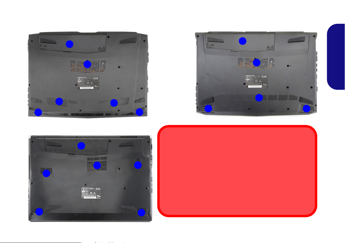
System Map: Bottom Views
Figure 10
Bottom Views
1. Battery
2. Vent
3. Speakers
2
1
3
2
3
Model B
Overheating
To prevent your computer from overheating make sure nothing
blocks any vent while the computer is in use.
Bottom Cover Removal Warning
Do not remove any cover(s) and/or screw(s) for the purposes of device upgrade as this may violate the terms of your warranty.
If you need to replace/remove the hard disk/RAM etc., for any reason, please contact your distributor/supplier for further information.
2
1
1
3
2
3
2
2
2
3
3
Model A
Model C
2
English
17
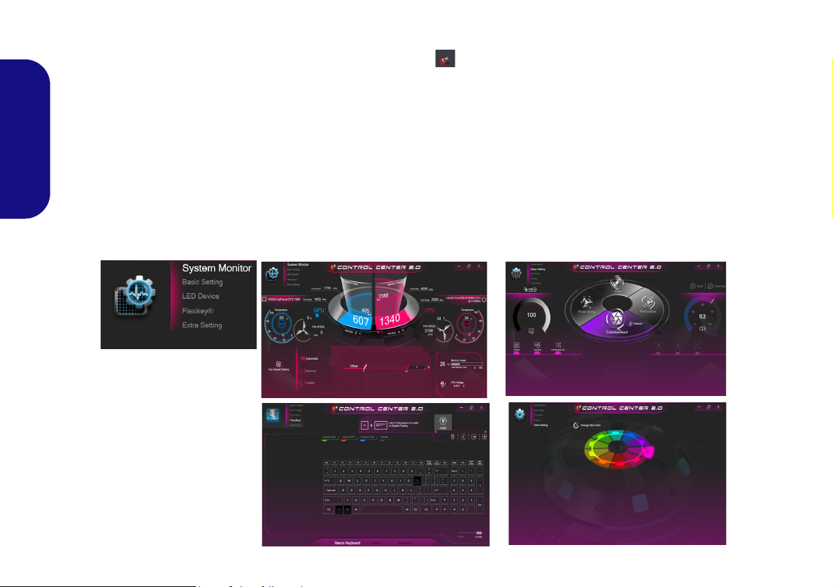
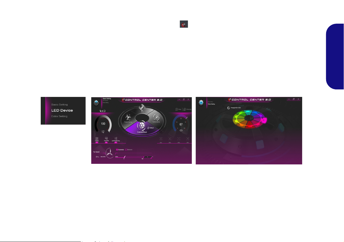
Control Center (Design I)
Figure 11
Control Center
Press the Fn + Esc key combination, or double-click the icon in the notification area of the taskbar to toggle the
Control Center on/off. The Control Center gives quick access to frequently used controls and enables you to quickly
turn the camera/Touchpad on/off.
Control Center Menus
The Control Center contains 4 menu headings (System Monitor, Basic Setting, Flexikey® and Extra Setting). The
English
System Monitor tab provides information on the computer’s GPU and CPU. The Basic Setting tab allows you to adjust
the power mode and other system features. Flexikey® is a quick hotkey configuration application. The Extra Setting
tab allows you to adjust the app skin color to your choice. A further menu item (LED Device) is available for systems
supporting illuminated white LED keyboards only. Click the menu headings and then click any of the buttons outlined
on the following pages.
18
Power Modes
You can set a Power Mode by clicking the appropriate
icon in the center
will affect the Airplane Mode and PC camera power.
of the Control Center. Each power mode
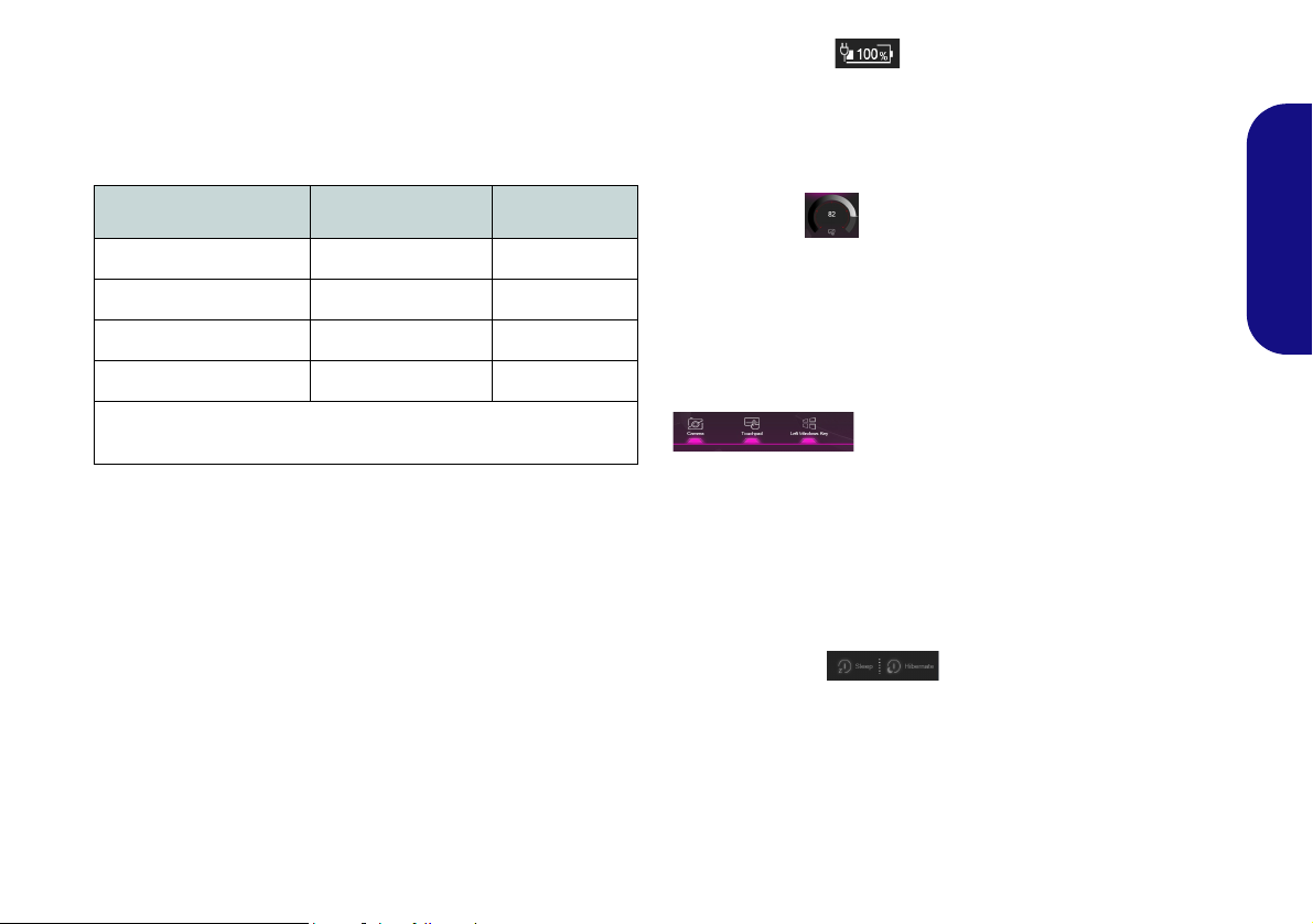
Power Status (Basic Setting)
The Power Status icon will show whether you are currently powered by the battery, or by the AC/DC adapter
plugged in to a working power outlet. The power status
bar will show the current battery charge state.
English
Mode Airplane Mode PC Camera
Power Saving ON OFF
Quiet OFF ON
Performance OFF ON
Entertainment* OFF ON
*Clicking the Default button in Entertainment will reset the default
settings for this mode.
Brightness (Basic Setting)
The Brightness icon will show the current screen brightness level. You can use the dial to adjust the screen brightness or the Fn + F8/F9 key combinations.
Camera/Touchpad/Left Windows Key (Basic
Setting)
Click these buttons to toggle the PC Camera or Touchpad power status, or to turn the Left Windows Key func-
tionality on/off. The button under the icon will appear
highlighted when it is enabled. Note that the power status
of the camera module is also effected by the Power Mode
selected.
Sleep Button (Basic Setting)
Click either the Hibernate or Sleep button to have the
computer enter the selected power-saving mode (you will
receive a warning before the system switches to the power-saving mode and will need to click OK to confirm).
19
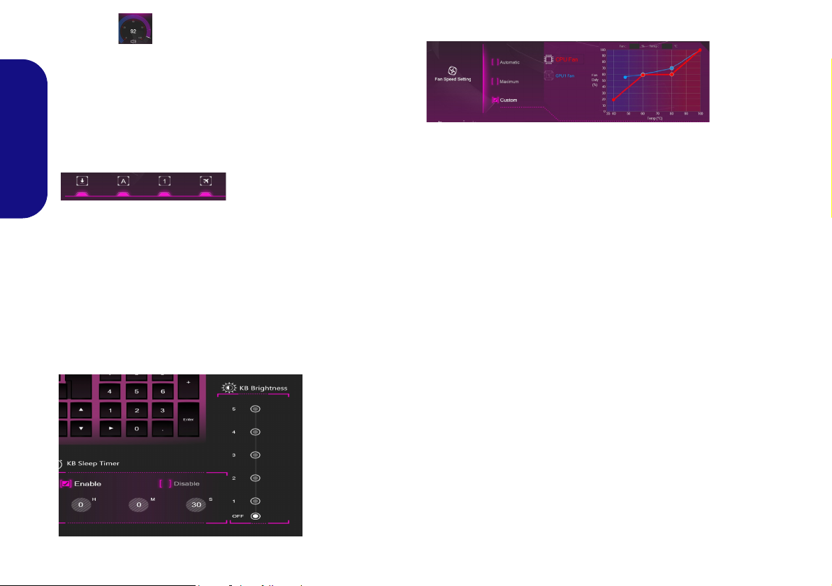
Volume (Basic Setting)
The Volume icon will show the current volume level. You
can use the dial to adjust the volume or the Fn + F5/F6
key combinations, or use the Fn + F3 key combination to
mute the volume.
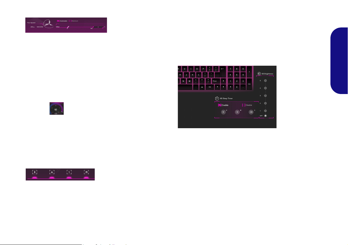
Fan (System Monitor)
Caps Lock/Scroll Lock/Number Lock/Airplane
Mode (Basic Setting)
English
Click the button to toggle the appropriate lock mode and
Airplane Mode.
KB Sleep Timer/KB Brightness (LED Device)
(For White-LED Keyboards)
Enable and then select the amount of time for which the
system is idle before the keyboard LED enters sleep mode
(i.e. the LED keyboard illumination will turn off to save
power). You can also adjust the keyboard brightness.
You can set the fan speed to Maximum (full power), Au-
tomatic or Custom from this menu item. The fan speed
will adjust itself automatically to control the heat of the
CPU/GPU. You can use the Offset slider to adjust the settings to your preference. However you can adjust the setting to Maximum if you prefer.
The Custom setting allows you to click and drag on any
of the 2 midrange nodes on the graph in order to adjust the
temperature parameters of the CPU Fan or GPU Fan.
All these settings can be overidden by the system, as a
safety precaution, if it requires heavier use of the fan.
20
Control Center (Design II)
Figure 12 - Control Center
Press the Fn + Esc key combination, or double-click the icon in the notification area of the taskbar to toggle the
Control Center on/off. The Control Center gives quick access to frequently used controls and enables you to quickly
turn the camera/Touchpad on/off.
Control Center Menus
The Control Center contains two menu headings (Basic Setting and Extra Setting). The Basic Setting tab allows you
to adjust the power mode and other system features. The Extra Setting tab allows you to adjust the app skin color to
your choice. A third menu item (LED Device) is available for systems supporting illuminated white LED keyboards
only. Click the menu headings and then click any of the buttons outlined on the following pages.
English
21
Power Modes
You can set a Power Mode by clicking the appropriate
icon in the center
mode will affect the Airplane Mode and PC camera power.
of the Control Center. Each power
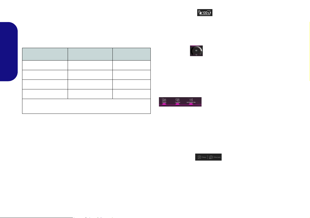
Power Status (Basic Setting)
The Power Status icon will show whether you are currently powered by the battery, or by the AC/DC adapter
plugged in to a working power outlet. The power status
bar will show the current battery charge state.
Mode Airplane Mode PC Camera
English
Power Saving ON OFF
Quiet OFF ON
Performance OFF ON
Entertainment* OFF ON
*Clicking the Default button in Entertainment will reset the default
settings for this mode.
Brightness (Basic Setting)
The Brightness icon will show the current screen brightness level. You can use the dial to adjust the screen brightness or the Fn + F8/F9 key combinations.
Camera/Touchpad/Left Windows Key (Basic
Setting)
Click these buttons to toggle the PC Camera or Touchpad power status, or to turn the Left Windows Key func-
tionality on/off. The button under the icon will appear
highlighted when it is enabled. Note that the power status
of the camera module is also effected by the Power Mode
selected.
Sleep Button (Basic Setting)
Click either the Hibernate or Sleep button to have the
computer enter the selected power-saving mode (you will
receive a warning before the system switches to the power-saving mode and will need to click OK to confirm).
22
Fan Speed (Basic Setting)
You can set the fan speed to Maximum (full power) or
Automatic from this menu item. The fan speed will adjust
itself automatically to control the heat of the CPU. You
can use the Offset slider to adjust the settings to your preference. However you can adjust the setting to Maximum
if you prefer.
All these settings can be overidden by the system, as a
safety precaution, if it requires heavier use of the fan.
Volume (Basic Setting)
The Volume icon will show the current volume level. You
can use the dial to adjust the volume or the Fn + F5/F6
key combinations, or use the Fn + F3 key combination to
mute the volume.
Caps Lock/Scroll Lock/Number Lock/Airplane
Mode (Basic Setting)
KB Sleep Timer/KB Brightness (LED Device)
(For White-LED Keyboards)
Enable and then select the amount of time the system for
which the system is idle before the keyboard LED enters
sleep mode (i.e. the LED keyboard illumination will turn
off to save power). You can also adjust the keyboard
brightness.
English
Click the button to toggle the appropriate lock mode and
Airplane Mode.
23
Flexikey® Application
Enabling or Disabling the Flexikey® Profile in Use
You can enable or disable any keyboard or mouse profile
functions currently in use by using the Fn + key
combination. Pressing this key combination will toggle you
between the currently selected keyboard or mouse profile
to the standard keyboard and/or mouse settings, and back
again.
Windows Logo Key and P key
Note that you can assign actions to any keyboard key except the Windows Logo Key and P key.
Figure 13
Flexikey -
Profile
(Design I Only)
The Flexikey® application is a quick hotkey configura-
tion application, which allows you to assign a single key
to launch multiple key combinations, or to launch pro-
grams and applications, to create text macros and to
disable certain keys. The application can also be used to
English
configure the mouse buttons to create hotkeys for gaming etc. All the configuration settings are retained under
profiles to which the settings are applied.
Click Flexikey® in the top left of the Control Center to
access the Flexikey® application.
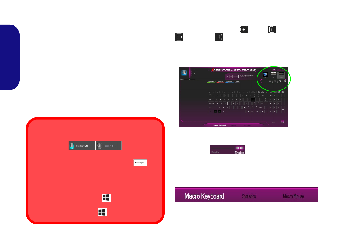
Profiles
The controls at the top right side of the application relate
to Profiles. You can Add /Delete profiles, Export
and Import profiles by clicking on the appropriate
icon. If you double-click on a profile you can change the
profile name, and change an image file (images created
using PNG files).
24
Keyboard and Mouse Settings
Click Enable (at the bottom right of the application window) to create settings for the keyboard and/
or mouse. Clicking on Macro Keyboard or Macro
Mouse will allow you to access the settings page for either
the keyboard or mouse.
Figure 14 - Enable (Macro Keyboard & Macro Mouse)
 Loading...