

Clevo N150RF, N151RF, N170RF, N171RF Concise User's Guide


Contents
About this Concise User Guide ......................................................... 1
System Startup ..................................................................................4
System Map: Front View with LCD Panel Open
(Models A, B & C) ............................................................................6
LED Indicators ..................................................................................7
Keyboard & Function Keys ..............................................................8
Control Center ...................................................................................9
Flexikey® Application ....................................................................11
System Map: Front, Left & Right Views (Model A) ......................15
System Map: Front, Left & Right Views (Model B) ......................16
System Map: Front, Left & Right Views (Model C) ......................17
System Map: Bottom & Rear Views (Models A & B) ...................18
System Map: Bottom & Rear Views (Model C) ............................. 19
Windows 10 Start Menu, Context Menu, Taskbar, Control Panel and
Settings ............................................................................................20
Video Features ................................................................................21
Power Options .................................................................................22
Audio Features ................................................................................ 23
Driver Installation ........................................................................... 24
Fingerprint Reader (Option) ...........................................................25
TPM (Option) ..................................................................................26
Troubleshooting ..............................................................................27
Specifications ..................................................................................28
Inhalt
Über das Ausführliche Benutzerhandbuch .....................................31
Schnellstart ......................................................................................34
Systemübersicht: Ansicht von vorne mit geöffnetem LCD-Bildschirm
(Modelle A, B & C) ........................................................................36
LED-Anzeigen ................................................................................37
Tastatur & Funktionstasten .............................................................38
Control Center .................................................................................39
Flexikey® Anwendung ...................................................................41
Systemübersicht: Ansicht von vorne, links und rechts
(Modell A) ......................................................................................45
Systemübersicht: Ansicht von vorne, links und rechts
(Modell B) ......................................................................................46
Systemübersicht: Ansicht von vorne, links und rechts
(Modell C) ......................................................................................47
Systemübersicht: Ansicht von unten und hinten
(Modelle A & B) .............................................................................48
Systemübersicht: Ansicht von unten und hinten (Modell C) ..........49
Start-Menü, Kontextmenü, Taskleiste, Systemsteuerung und
Einstellungen von Windows 10 .......................................................50
Grafikfunktionen .............................................................................51
Energieoptionen ..............................................................................52
Audiofunktionen ..............................................................................53
Installation der Treiber ....................................................................54
Fingerabdruckleser (Option) ...........................................................55
TPM (Option) ..................................................................................56
Fehlerbehebung ...............................................................................57
Technische Daten ............................................................................58
Sommaire
A propos de ce Guide Utilisateur Concis ........................................61
Guide de démarrage rapide .............................................................64
Carte du système: Vue de face avec l’écran LCD ouvert
(Modèles A, B & C) ........................................................................66
Indicateurs LED ..............................................................................67
Clavier & touches fonction .............................................................68
Control Center .................................................................................69
Application Flexikey® ....................................................................71
Carte du système: Vues de face, gauche et droite (Modèle A) ......75
Carte du système: Vues de face, gauche et droite (Modèle B) ......76
Carte du système: Vues de face, gauche et droite (Modèle C) ......77
Carte du système: Vues de dessous et arrière (Modèles A & B) ....78
Carte du système: Vues de dessous et arrière (Modèle C) .............79

Menu Démarrer, Menu contextuel, Barre des tâches, Panneau de
Configuration et Paramètres de Windows 10 .................................80
Caractéristiques vidéo .....................................................................81
Options d’alimentation ....................................................................82
Caractéristiques audio .....................................................................83
Installation du pilote ....................................................................... 84
Lecteur d'empreintes digitales (Option) .......................................... 85
TPM (Option) ..................................................................................86
Dépannage .......................................................................................87
Spécifications ..................................................................................88
Contenidos
Acerca de esta Guía del Usuario Concisa ....................................... 91
Guía rápida para empezar ...............................................................94
Mapa del sistema: Vista frontal con panel LCD abierto
(Modelos A, B & C) .......................................................................96
Indicadores LED ............................................................................. 97
Teclado & teclas de función ........................................................... 98
Control Center .................................................................................99
Aplicación Flexikey® ...................................................................101
Mapa del sistema: Vistas frontal, izquierda y derecha
(Modelo A) ....................................................................................105
Mapa del sistema: Vistas frontal, izquierda y derecha
(Modelo B) .................................................................................... 106
Mapa del sistema: Vistas frontal, izquierda y derecha
(Modelo C) .................................................................................... 107
Mapa del sistema: Vistas inferior y posterior (Modelos A & B) ..108
Mapa del sistema: Vistas inferior y posterior (Modelo C) ...........109
Menú Inicio, Menú contextual, Barra de tareas, Panel de Control
y Configuración de Windows 10 ..................................................110
Parámetros de vídeo ...................................................................... 111
Opciones de energía ......................................................................112
Características de audio ................................................................113
Instalación de controladores .........................................................114
Lector de huellas digitales (Opción) .............................................115
TPM (Opción) ...............................................................................116
Solución de problemas ..................................................................117
Especificaciones ............................................................................118
Sommario
Informazioni sulla Guida Rapida per l'Utente ...............................121
Guida di avvio rapido ....................................................................124
Descrizione del sistema: Vista anteriore con pannello LCD aperto
(Modelli A, B & C) .......................................................................126
Indicatori LED ...............................................................................127
Tastiera & tasti funzione ...............................................................128
Control Center ...............................................................................129
Applicazione Flexikey® ................................................................131
Descrizione del sistema: Vista anteriore, sinistra e destra ............135
(Modello A) ...................................................................................135
Descrizione del sistema: Vista anteriore, sinistra e destra ............136
(Modello B) ...................................................................................136
Descrizione del sistema: Vista anteriore, sinistra e destra ............137
(Modello C) ...................................................................................137
Descrizione del sistema: Vista inferiore e posteriore
(Modelli A & B) ............................................................................138
Descrizione del sistema: Vista inferiore e posteriore
(Modello C) ..................................................................................139
Menu Start, Menu contestuale, Barra delle applicazioni, Pannello
di controllo e Impostazioni di Windows 10 ..................................140
Funzioni video ...............................................................................141
Opzioni risparmio energia .............................................................142
Funzionalità audio .........................................................................143
Installazione driver ........................................................................144
Lettore d’impronte digitali (Opzione) ...........................................145
TPM (Opzione) .............................................................................146
Risoluzione dei problemi ..............................................................147
Specifiche tecniche ........................................................................148

About this Concise User Guide
FCC Statement
This device complies with Part
15 of the FCC Rules. Operation
is subject to the following two
conditions:
1. This device may not cause
harmful interference.
2. This device must accept any
interference received, including interference that may
cause undesired operation.
This quick guide is a brief introduction to getting your system started. This is a supplement, and not a substitute for the
expanded English language User’s Manual in Adobe Acrobat format on the Device Drivers & Utilities + User’s Manual
disc supplied with your computer. This disc also contains the drivers and utilities necessary for the proper operation of
the computer (Note: The company reserves the right to revise this publication or to change its contents without notice).
Some or all of the computer’s features may already have been setup. If they aren’t, or you are planning to re-configure
(or re-install) portions of the system, refer to the expanded User’s Manual. The Device Drivers & Utilities + User’s
Manual disc does not contain an operating system.
Regulatory and Safety Information
Please pay careful attention to the full regulatory notices and safety information
contained in the expanded User’s Manual on the Device Drivers & Utilities + Us-
er’s Manual disc.
© December 2015
Trademarks
Intel and Intel Core are trademarks/registered trademarks of Intel Corporation.
English
1

Instructions for Care and Operation
The computer is quite rugged, but it can be damaged. To
prevent this, follow these suggestions:
• Don’t drop it, or expose it to shock. If the computer falls, the
case and the components could be damaged.
• Keep it dry, and don’t overheat it. Keep the computer and
power supply away from any kind of heating element. This is an
English
electrical appliance. If water or any other liquid gets into it, the
computer could be badly damaged.
• Avoid interference. Keep the computer away from high capacity
transformers, electric motors, and other strong magnetic fields.
These can hinder proper performance and damage your data.
• Follow the proper working procedures for the computer. Shut
the computer down properly and don’t forget to save your work.
Remember to periodically save your data as data may be lost.
• Note that in computer’s featuring a raised LCD electro-plated
logo, the logo is covered by a protective adhesive. Due to general
wear and tear, this adhesive may deteriorate over time and the
exposed logo may develop sharp edges. Be careful when handling
the computer in this case, and avoid touching the raised LCD
electro-plated logo. Avoid placing any other items in the carrying
bag which may rub against the top of the computer during transport. If any such wear and tear develops contact your service center.
Power & Battery Safety
• Only use an AC/DC adapter approved for use with this computer.
• Use only the power cord and batteries indicated in this manual.
• Your AC/DC adapter may be designed for international travel but
it still requires a steady, uninterrupted power supply. If you are
unsure of your local power specifications, consult your service
representative or local power company.
• The AC/DC adapter may have either a 2-prong or a 3-prong
grounded plug. The third prong is an important safety feature; do
not defeat its purpose. If you do not have access to a compatible
outlet, have a qualified electrician install one.
• When you want to unplug the power cord, be sure to disconnect it
by the plug head, not by its wire.
• Make sure the socket and any extension cord(s) you use can support the total current load of all the connected devices.
• Make sure that your computer is completely powered off before
putting it into a travel bag (or any such container).
• Only use batteries designed for this computer. The wrong battery
type may explode, leak or damage the computer.
• Do not continue to use a battery that has been dropped, or that
appears damaged (e.g. bent or twisted) in any way. Even if the
computer continues to work with a damaged battery in place, it
may cause circuit damage, which may possibly result in fire.
• Recharge the batteries using the computer’s system. Incorrect
recharging may make the battery explode.
• Do not try to repair a battery pack. Refer any battery pack repair
or replacement to your service representative or qualified service
personnel.
• Keep children away from, and promptly dispose of a damaged
battery. Always dispose of batteries carefully. Batteries may
explode or leak if exposed to fire, or improperly handled or discarded.
• Keep the battery away from metal appliances.
• Affix tape to the battery contacts before disposing of the battery.
• Do not dispose of batteries in a fire. They may explode. Check
with local codes for possible special disposal instructions.
• Do not touch the battery contacts with your hands or metal
objects.
2

Polymer Battery Precautions
Battery Disposal & Caution
The product that you have purchased contains a rechargeable battery. The battery is recyclable. At the end of its useful life, under various state and local laws, it may be illegal
to dispose of this battery into the municipal waste stream.
Check with your local solid waste officials for details in your
area for recycling options or proper disposal.
Danger of explosion if battery is incorrectly replaced. Replace only with the same or equivalent type recommended
by the manufacturer. Discard used battery according to the
manufacturer’s instructions.
Note the following information which is specific to polymer batteries only, and where applicable, this overrides
the general battery precaution information.
• Polymer batteries may experience a slight expansion or swelling,
however this is part of the battery’s safety mechanism and is not a
cause for concern.
• Use proper handling procedures when using polymer batteries.
Do not use polymer batteries in high ambient temperature environments, and do not store unused batteries for extended periods.
Cleaning
• Use a soft clean cloth to clean the computer, but do not apply
cleaner directly to the computer.
• Do not use volatile (petroleum distillates) or abrasive cleaners on
any part of the computer.
• Before cleaning the computer remove the battery and make sure
the computer is disconnected from any external power supplies,
peripherals and cables (including telephone lines).
Servicing
Attempting to service the computer yourself may violate
your warranty and expose you and the computer to electric
shock. Refer all servicing to qualified service personnel,
particularly under any of the following conditions:
English
• When the power cord or AC/DC adapter is damaged or frayed.
• If the computer has been exposed to any liquids.
• If the computer does not work normally when you follow the
operating instructions.
• If the computer has been dropped or damaged (do not touch the
poisonous liquid if the LCD panel breaks).
• If there is an unusual odor, heat or smoke coming from your computer.
3
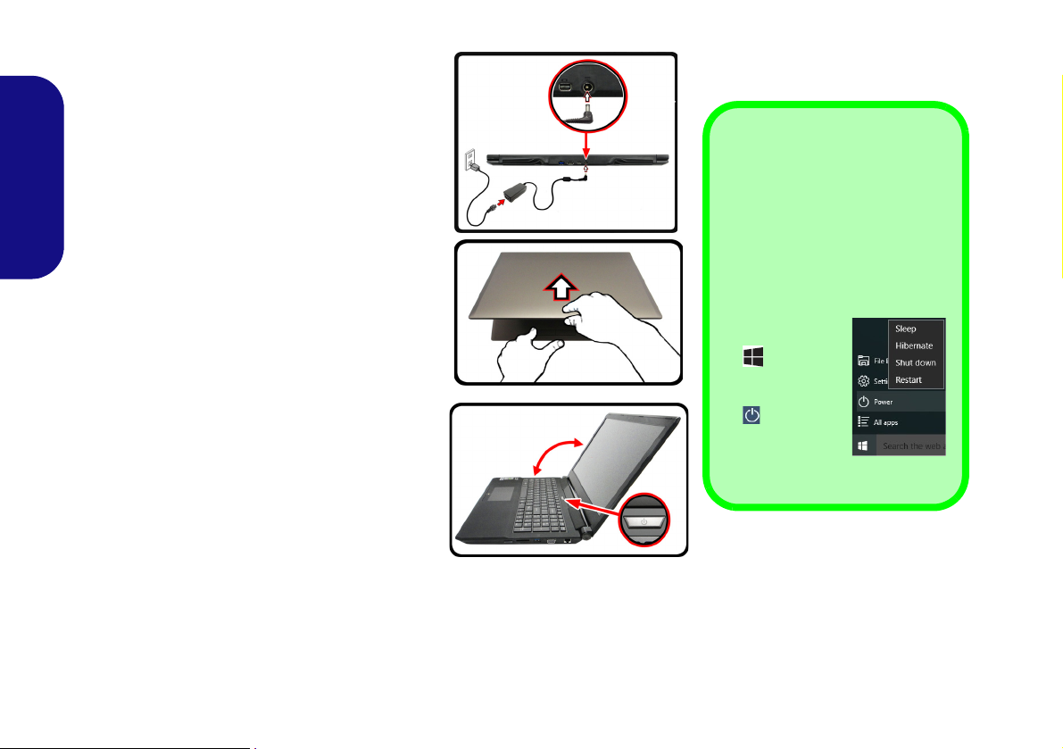
System Startup
Figure 1
Opening the Lid/LCD/
Computer with AC/DC
Adapter Plugged-In
Shut Down
Note that you should always shut
your computer down by choosing
the Shut down command in Win-
dows (see below). This will help
prevent hard disk or system problems.
1. Click the Start
Menu icon
.
2. Click the
Power item
.
3. Choose Shut
Down from
the menu.
135°
1. Remove all packing materials.
2. Place the computer on a stable surface.
3. Securely attach any peripherals you want to use
with the computer (e.g. keyboard and mouse) to
their ports.
4. Attach the AC/DC adapter to the DC-In jack on the
rear of the computer, then plug the AC power cord
English
into an outlet, and connect the AC power cord to
the AC/DC adapter (make sure you use the
adapter when first setting up the computer, as
to safeguard the computer during shipping the
battery will be locked to not power the system until
first connected to the AC/DC adapter).
5. Use one hand to raise the lid/LCD to a comfortable
viewing angle (do not to exceed 135 degrees);
the other hand (as illustrated in Figure 1) to
support the base of the computer (Note: Never lift
the computer by the lid/LCD).
6. Press the power button to turn the computer “on”.
System Software
Your computer may already come with system
software pre-installed. Where this is not the
case, or where you are re-configuring your
computer for a different system, you will find
this manual refers to Microsoft Windows 10.
use
4
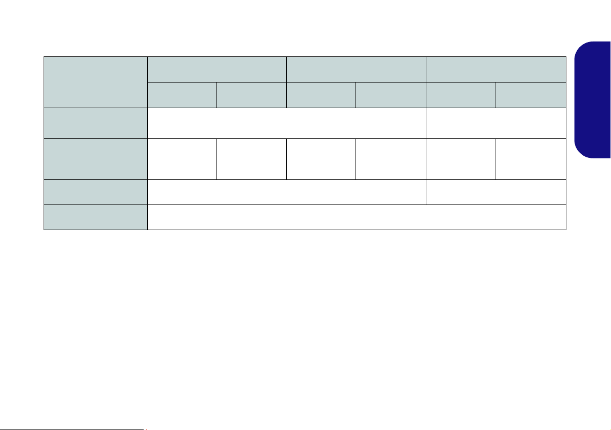
Model Differences
This notebook series includes three different model types that mainly differ as indicated in the table below.
Feature
Display Type
NVIDIA® Discrete GPU
3G/4G Module
Dimensions & Weight
Model A Model B Model C
Design I Design II Design I Design II Design I Design II
15.6" (39.62cm), 16:9, QFHD (3840x2160)/FHD (1920x1080)
NVIDIA®
GeForce GTX
960M
NVIDIA®
GeForce GTX
965M
Factory Option No
See Dimensions & Weight on page 29 for details.
NVIDIA®
GeForce GTX
960M
NVIDIA®
GeForce GTX
965M
17.3" (43.94cm)
(1920x1080)
NVIDIA®
GeForce GTX
960M
, 16:9, FHD
NVIDIA®
GeForce GTX
965M
Table 1 - Model Differences
English
5
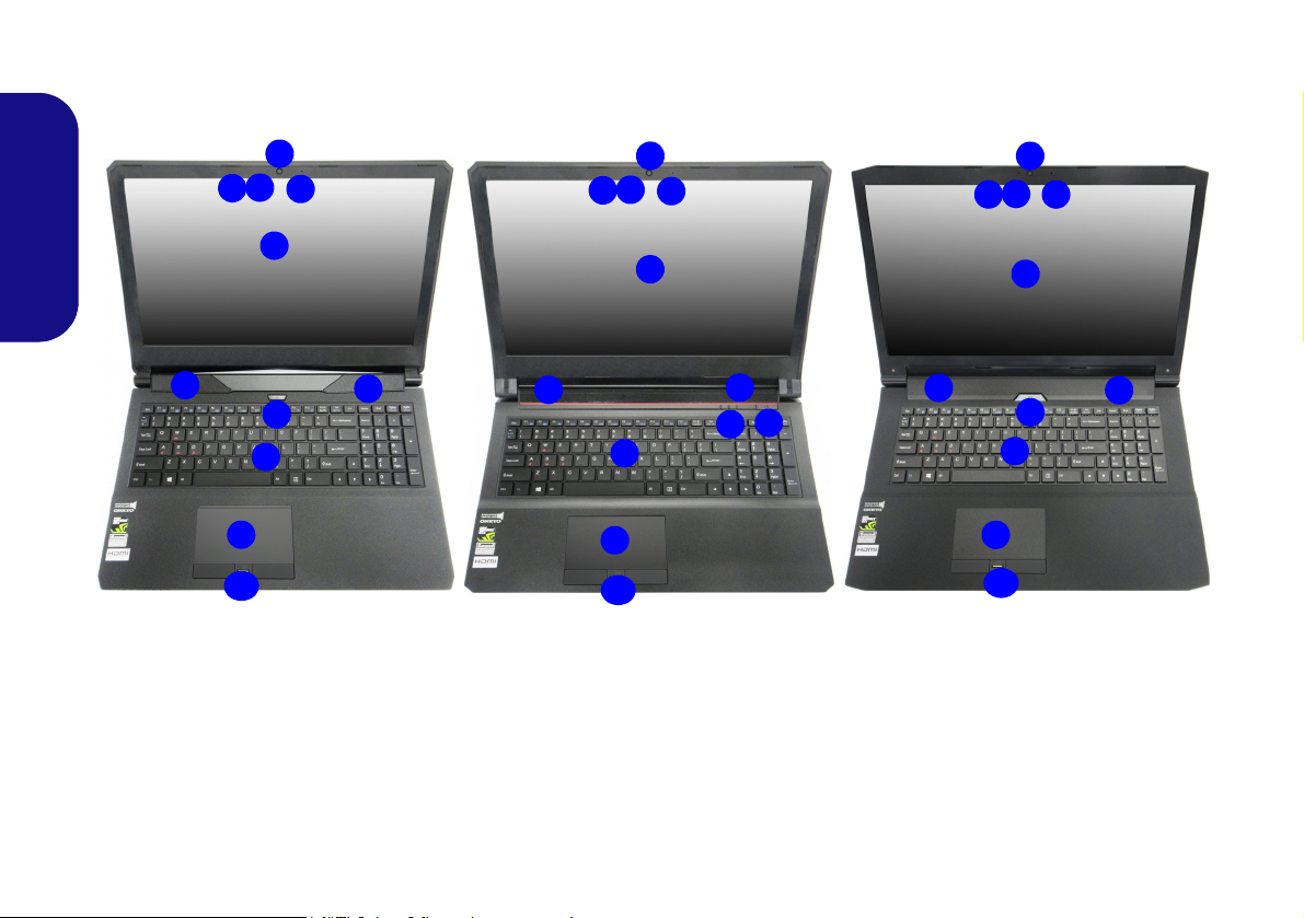
System Map: Front View with LCD Panel Open
2
1
9
8
4
Figure 2 - Front View with LCD Panel Open (Models A, B & C)
1. PC Camera
2. Built-In Array Microphone
3. *PC Camera LED
*When the PC camera is in use, the
LED will be illuminated.
4. LCD
5. Power Button
6. Speakers
7. LED Indicators
8. Keyboard
9. Touchpad & Buttons
10. Fingerprint Reader (Optional)
2
15.6” (39.62cm)
17.3” (43.94cm)
6
6
8
5
4
9
Model A
15.6” (39.62cm)
6
6
Model C
9
5
6
6
5
7
8
4
Model B
10
10
10
3
2
1
2
3
2
1
2
3
(Models A, B & C)
English
6
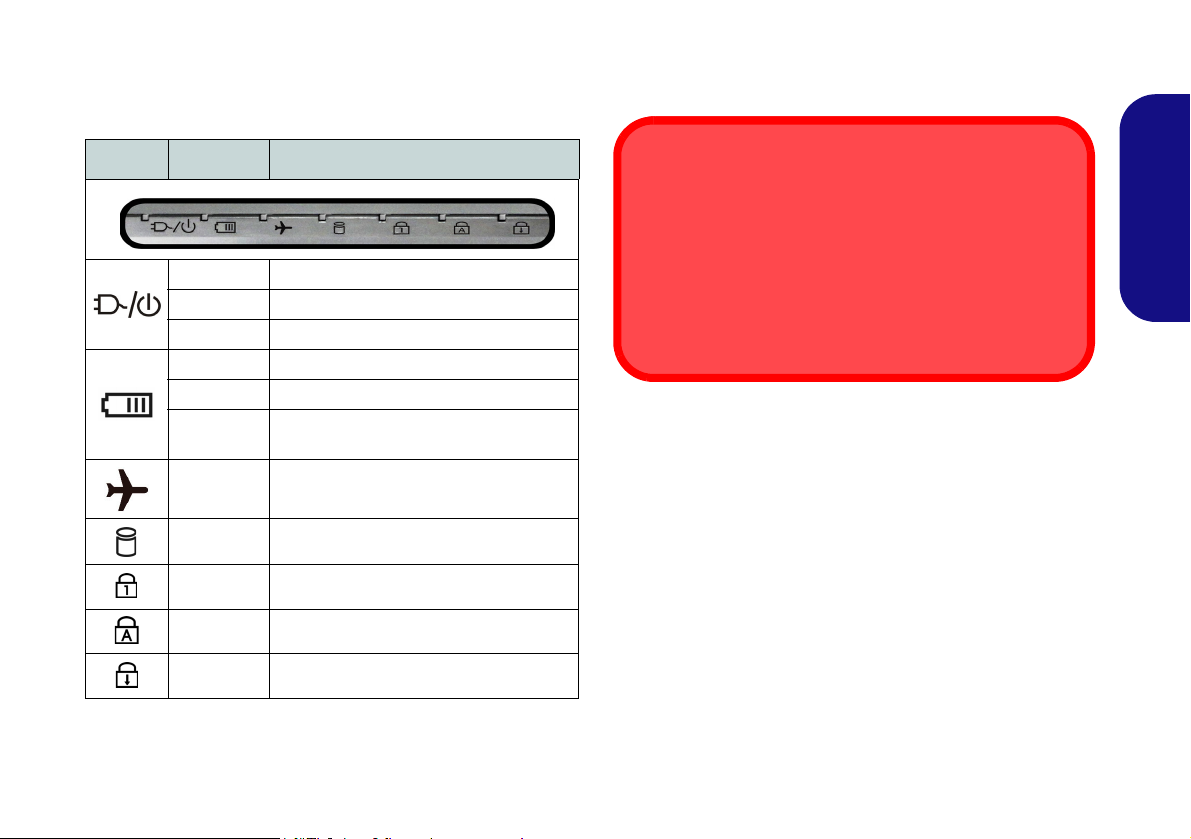
LED Indicators
Wireless Device
Operation Aboard Aircraft
The use of any portable electronic transmission devices
aboard aircraft is usually prohibited.
Make sure the wireless modules are OFF if you are using
the computer aboard aircraft by putting the system in to Airplane Mode.
The LED indicators on the computer display helpful information about the current status of the computer.
Icon Color Description
Orange The AC/DC Adapter is Plugged In
White The Computer is On
White The Computer is in Sleep Mode
Orange The Battery is Charging
White The Battery is Fully Charged
Blinking
Orange
White
White The Hard Disk/Optical Device is in use
White Number Lock (Numeric Keypad) Activated
White Caps Lock Activated
White Scroll Lock Activated
The Battery Has Reached Critically Low
Power Status
Airplane Mode is ON (the WLAN, Blue-
tooth and 3G/4G Modules are OFF)
Table 2 - LED Indicators
English
7
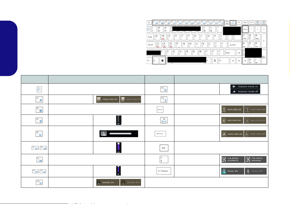
Keyboard & Function Keys
Function Keys
Numeric
Keypad
Fn Key
Windows Logo Key
ScrLk &
NumLk
Figure 3 - Keyboard
The keyboard includes a numeric keypad for easy numeric
data input. Pressing NumLk turns on/off the numeric keypad. It also features function keys to allow you to change
operational features instantly. The function keys (F1 -
F12 etc.) will act as hot keys when pressed while the Fn
key is held down. In addition to the basic function key
combinations, some visual indicators are available when
English
the Control Center driver is installed.
Keys Function/Visual Indicators Keys Function/Visual Indicators
Fn +
Fn +
Fn +
Fn +
Fn +
Fn +
Fn +
Fn +
Fn +
8
Play/Pause (in Audio/Video Programs)
Touchpad Toggle
(Press a key to or use Touchpad to turn on)
Mute Toggle
Toggle Keyboard Illumi-
nation/Adjust Brightness
Volume Decrease/
Change Display Configuration (see page 22)
Brightness Decrease/
PC Camera Power
Turn LCD Backlight Off
Level
Increase
Increase
Toggle
Fn +
Fn +
Fn +
Fn +
Fn +
Fn +
Airplane Mode Toggle
Sleep Toggle
Number Lock Toggle
Scroll Lock Toggle
Caps Lock Toggle
Control Center Toggle (see page 9)
Fan Automatic Control/
Full Power
Disable/Enable Flexikey®
(see page 11)
Table 3 - Function Keys & Visual Indicators
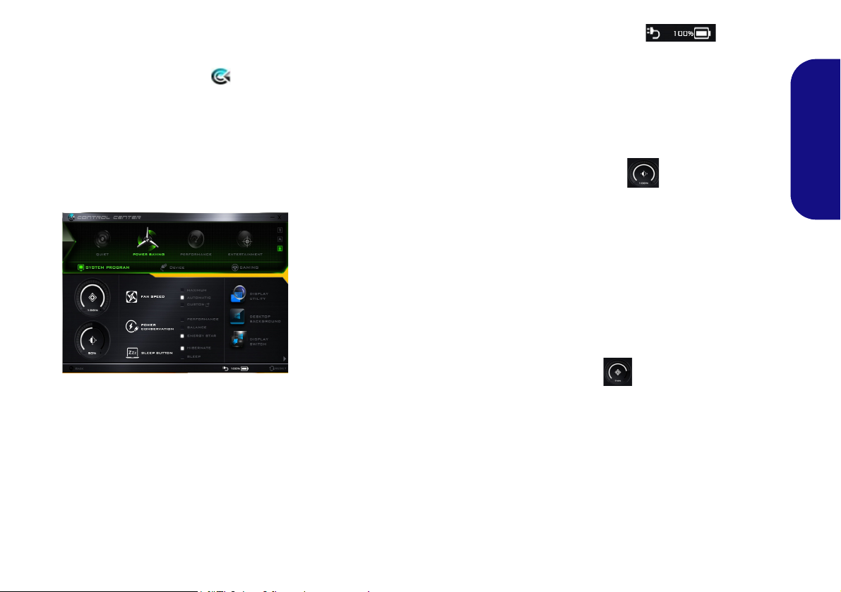
Control Center
Figure 4 - Control Center
Press the Fn + Esc key combination,
or double-click the icon in the no-
tification area of the taskbar to toggle the Control Center on/off. The
Control Center gives quick access to
frequently used controls and enables
you to quickly turn the camera/Touchpad on/off.
Power Modes
You can set a Power Mode by clicking the appropriate icon at the top of
the Control Center. Each power
mode will affect the Power Conservation Mode, Airplane Mode, Power
Plan and PC camera power etc.
Control Center Menus
The Control Center contains 3 menu
headings (System Program, Device
and Gaming) under the Power Modes.
Click the Control Center icons to
toggle the appropriate function, or
hold the mouse button down and move
the dial control where applicable. Certain functions will automatically be
adjusted when a power mode is selected. Click the menu headings and then
click any of the buttons.
Power Status
The Power Status icon will show
whether you are currently powered by
the battery, or by the AC/DC adapter
plugged in to a working power outlet.
The power status bar will show the
current battery charge state.
Brightness
The Brightness icon will show the
current screen brightness level. You
can use the slider to adjust the screen
brightness or the Fn + F8/F9 key combinations, or use the Fn + F2 key combination to turn off the LED backlight
(press any key to turn it on again).
Note that screen brightness is also effected by the Power Mode selected.
Volume
The Volume icon will show the current volume level. You can use the
slider to adjust the volume or the Fn +
F5/F6 key combinations, or use the
Fn + F3 key combination to mute the
volume.
English
9
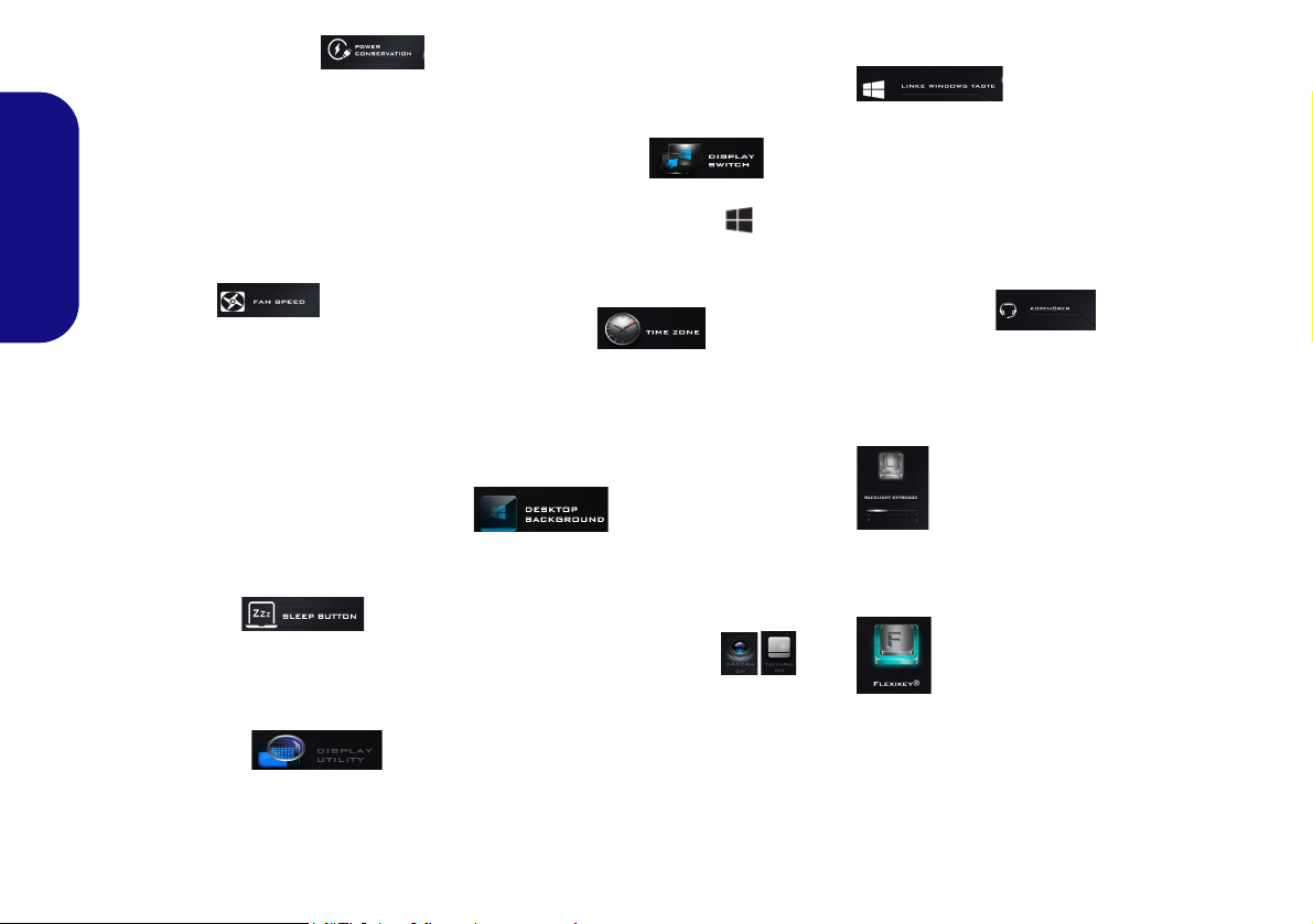
Power Conservation
This system supports Energy Star
power management features that place
computers (CPU, hard drive, etc.) into
a low-power sleep mode after a designated period of inactivity. Click either
the Performance, Balanced or Ener-
gy Star button.
English
Fan Speed
The fan speed will adjust itself automatically to control the heat of the
CPU. However you can adjust the setting to maximum if you prefer. Select
Custom and click on the sliders to adjust the settings to your preference,
however these settings can be overidden by the system, as a safety precaution, if it requires heavier use of the fan.
Sleep Button
Click either the Hibernate or Sleep
button to have the computer enter the
selected power-saving mode.
Display Utility
The Display Utility icon will only ap-
pear in the System Program menu if
your display’s resolution is QHD or
above. The Display Utility allows you
to adjust text size on the screen to
make it easier to view.
Display Switch
Click the Display Switch button to access the menu (or use the + P key
combination) and select the appropriate display mode.
Time Zone
Clicking the Time Zone button will
access the Date and Time Windows
control panel.
Desktop Background
Clicking the Desktop Background
button will allow you to change the
desktop background picture.
Touchpad/PC Camera
Click either of these buttons to toggle
the Touchpad or camera module’s
power status. Note that the power status of the camera module is also effected by the Power Mode selected.
Left Windows Key
Click Disable to disable the Windows
Key on the left side of the keyboard.
This may be useful if you are using the
gaming keys (W, A, S & D) and wish
to avoid accidentally triggering menus
with the Windows Key.
Headphone
The headphones may be set for different effects using this menu.
Backlight Keyboard
Click the numbers under
the Backlight Keyboard icon
to adjust the brightness of the
keyboard backlight LED.
Flexikey®
Click the button to access
the Flexikey® application.
10

Flexikey® Application
Enabling or Disabling the Flexikey® Profile in Use
You can enable or disable any keyboard or mouse profile
functions currently in use by using the Fn + key
combination. Pressing this key combination will toggle you
between the currently selected keyboard or mouse profile
to the standard keyboard and/or mouse settings, and back
again.
Windows Logo Key and P key
Note that you can assign actions to any keyboard key except the Windows Logo Key and P key.
Figure 5
Flexikey®
Applica-
tion
The Flexikey® application is a quick hotkey configura-
tion application, which allows you to assign a single key
to launch multiple key combinations, or to launch pro-
grams and applications, to create text macros and to
disable certain keys. The application can also be used to
configure the mouse buttons to create hotkeys for gam-
ing etc. All the configuration settings are retained under
(up to12) profiles to which the settings are applied.
The Flexikey® application can be accessed by clicking
the button
ter or by clicking the icon
the desktop taskbar.
in the Gaming section of the Control Cen-
in the notification area of
Profiles
The menus on the left side of the application relate to Profiles. You can Add or Delete profiles (you can maintain
12 active Profiles), Export and Import profiles from the
menus. If you double-click on a profile you can change the
Profile Name, and change an Image file (images created
using PNG files).
English
Keyboard and Mouse Settings
Click Enable to create settings for the keyboard and/or
mouse by clicking the button on the top left of the screen
(e.g. you may wish to create a profile with settings only
for the mouse or keyboard). Clicking on the keyboard or
mouse icons will allow you to access the settings page for
either the keyboard or mouse.
Figure 6 - Enable (Keyboard & Mouse)
11
English
123
4
5
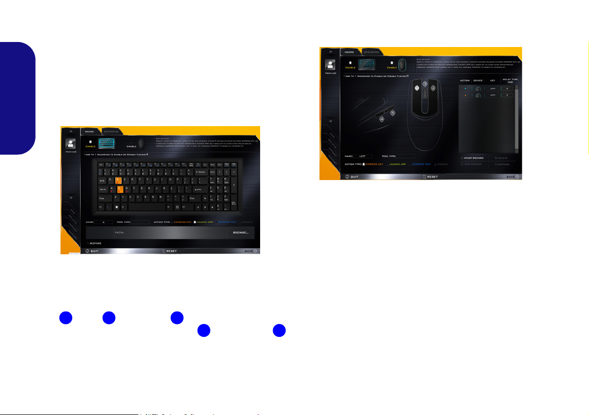
Keyboard Settings
The keyboard settings allow you to configure actions for
any single key (or a combination of keys). Click the key
and then select the Action Type (Express Key, Launch
App, Express Text or Disable) from the menu at the bottom of the page. You can rename the action by clicking in
the Name box, and click in Tool Tips to type in a note to
remind you of the action’s function.
Figure 7 - Keyboard Configuration
Mouse Settings
The mouse settings allow you to configure actions for the
left , right and middle buttons of any attached
mouse, and also for any backward and forward
buttons if applicable (on a gaming type mouse). Click the
button number and then select the Action Type (Express
Key, Launch App, Express Text or Disable) from the
menu at the bottom of the page. You can rename the action
12
by clicking in the Name box, and click in Tool Tips to
type in a note to remind you of the action’s function.
Figure 8 - Mouse Configuration
Flexikey® Application Features:
• EXPRESS KEY - This feature allows you to configure a
single key (or mouse click) to send multiple key combinations, or to create more useful shortcut keys This is useful
in gaming or when using applications which have a complex set of keyboard shortcuts.
• LAUNCH APP - This simply assigns single keys (or
mouse clicks) to launch any program’s or application’s
executable file.
• EXPRESS TEXT - With this you can assign single keys
(or mouse clicks) to send commonly used strings of text.
• DISABLE - Use this function to disable any keyboard
keys or mouse buttons.
• STATISTICS - Use this to quickly record keys in use in
any application, and to disable unused keys.
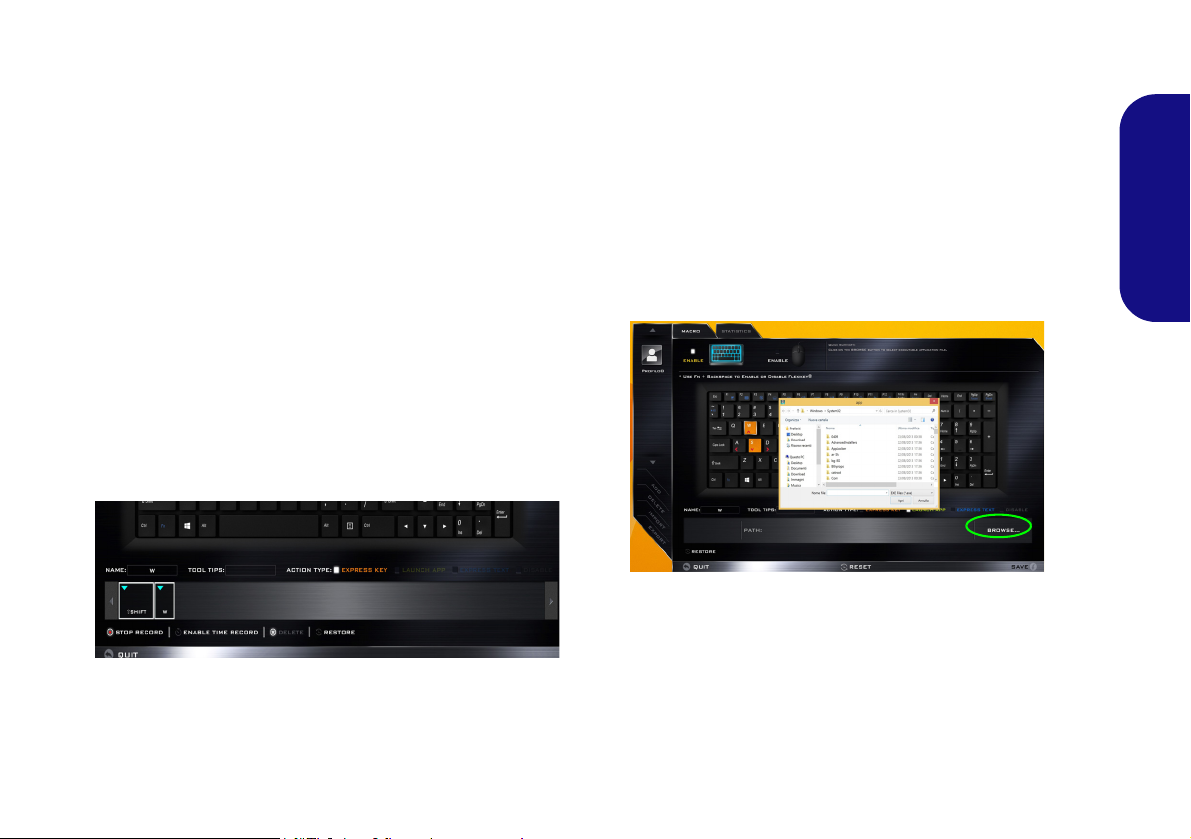
Keyboard Settings - Express Key
To configure a single key to send multiple key combinations, or to create more useful shortcut keys, use Express
Key.
1. Enable and select the keyboard under your chosen profile, click
on a key to select it, and then click to select Express Key in
Action Type.
2. In the following example we want to change an existing game
key configuration which uses the left shift key for sprinting, and
the W key for moving forwards, to use the left Ctrl key to
combine this movement to sprint forward.
3. Click on the chosen key for the shortcut action.
4. Click in the Tool Ti ps field and type to give the key combination
a name e.g. “Sprint Fwds”, then click back in the Name field (to
avoid adding the recorded keys to the Tool Tips name).
5. Click Start Record and then press the key or keys (in this case
we will press Left Shift and W) required (make sure you press
the key(s) required and do not click on them).
6. Click Stop Record to complete the process.
9. If you want to clear all the settings click Restore to return to the
default key setting.
10. Any assigned Express Keys will appear in orange.
Keyboard Settings - Launch App
You can configure keys to launch any application or program as follows:
1. Enable and select the keyboard under your chosen profile, click
to select a key to launch the appllication, and then click to select
Launch App in Action Type.
2. Click Browse... at the bottom right of the application window.
Figure 10 - Keyboard - Launch App
English
Figure 9 - Keyboard - Express Key
7. Click Save to save the settings within your chosen profile.
8. If you want to remove any individual key click to select it, and
then click Delete.
3. Navigate to the executable file of the application and click
Open.
4. The key will now be configured to open the selected application
under your chosen Profile, and the key will appear in green.
5. If you want to remove any Launch App key, select it and click
on Restore.
6. Click Save to save the settings within your chosen profile.
13
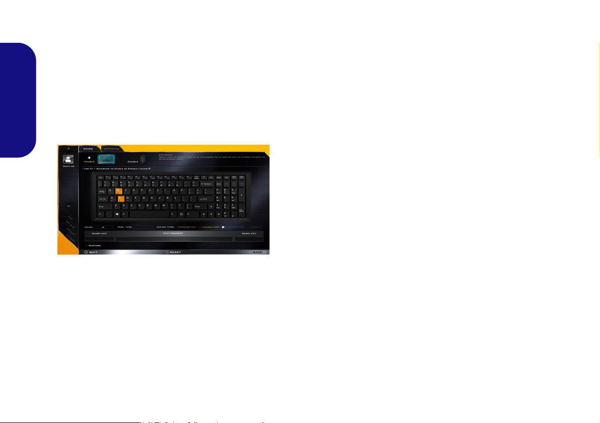
Keyboard Settings - Express Text
A single key can be set to send a string of text within any
application using Express Text.
1. Enable and select the keyboard under your chosen profile, click
to select a key, and then click to select Express Text in Action
Typ e.
2. Click in Start key if required (the Start key is the key used in
your target program to open a text message), or you can leave
English
it blank if you prefer.
3. Click in the Click to type field and type in your message.
Figure 11 - Keyboard - Express Text
4. Click in Send key if required (the Send key is the key used in
your target program to send a text message e.g the Enter key
would be the most commonly used), or you can leave it blank if
you prefer.
5. The key will now be configured to send the text message in the
target program under your chosen Profile, and the key will
appear in blue.
6. If you want to remove any Express Text key, select it and click
on Restore.
7. Click Save to save the settings within your chosen profile.
Keyboard Settings - Disable
You can use the program to disable any keys not required.
1. Enable and select the keyboard under your chosen profile, click
to select a key to disable, and then click to select Disable in
Action Type.
2. The key will now be disabled.
3. If you want to enable the key again, select it and click on
Restore.
4. Click Save to save the settings within your chosen profile.
5. The key will be disabled under your chosen Profile, and the key
will appear in gray.
14
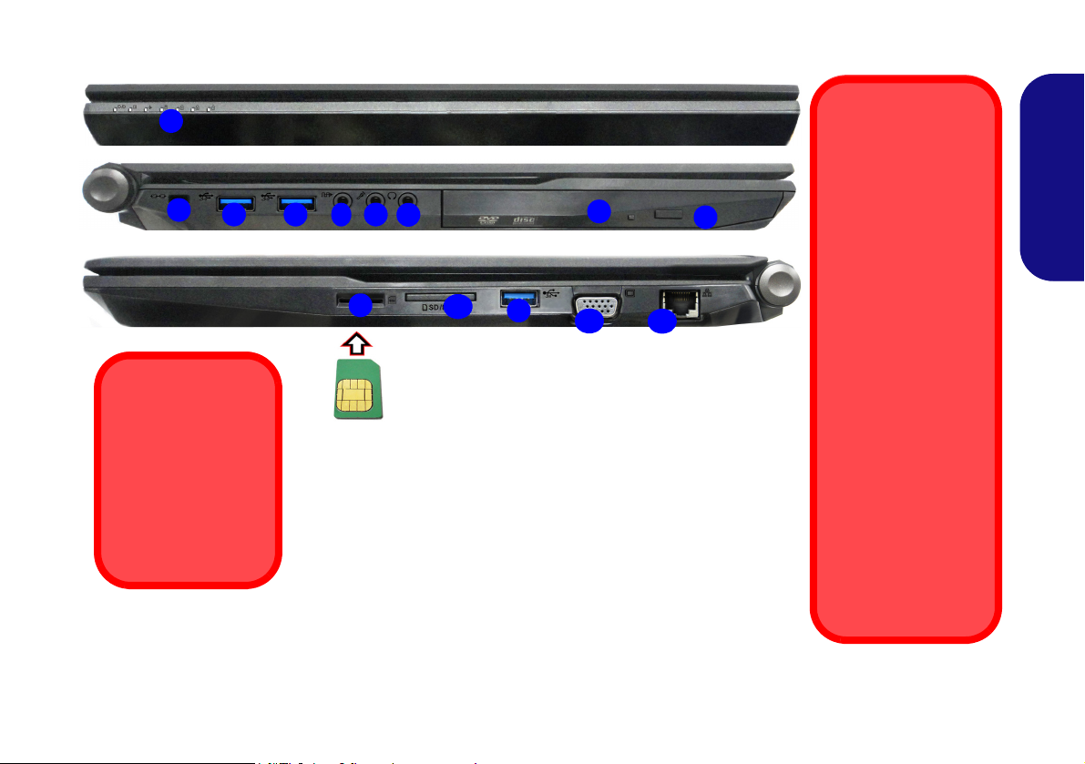
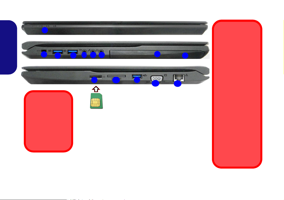
System Map: Front, Left & Right Views (Model A)
3
6
4
5
1
Front
Left
Right
11
7
12
10
2
Figure 12 - Front, Left & Right Views (Model A)
1. LED Indicators
2. Security Lock Slot
3. USB 3.0 Ports
4. S/PDIF-Out Jack
5. Microphone Jack
6. Headphone Jack
7. Optical Device Drive Bay
8. Emergency Eject Hole
(see page 17)
9. USIM Card Reader (for
3G/4G USIM Cards)
10. Multi-in-1 Card Reader
11. External Monitor Port
12. RJ-45 LAN Jack
USIM Card
Orientation
Note that the USIM
card’s readable side
(with the gold-colored contacts)
should face upwards
as illustrated.
8
9
3
3
USIM Card Ejection
Simply press on the
USIM card to eject it,
however do not do
this while a connection is in progress.
If you do eject the card
while a 3G/4G connection is ongoing,
you will need to shut
down the system, reinsert the USIM card,
restart the system and
then reestablish the
3G/4G connection.
If you wish to change
USIM cards then you
will also need to shut
down the system, reinsert the USIM card,
restart the system and
then reestablish the
3G/4G connection.
English
15
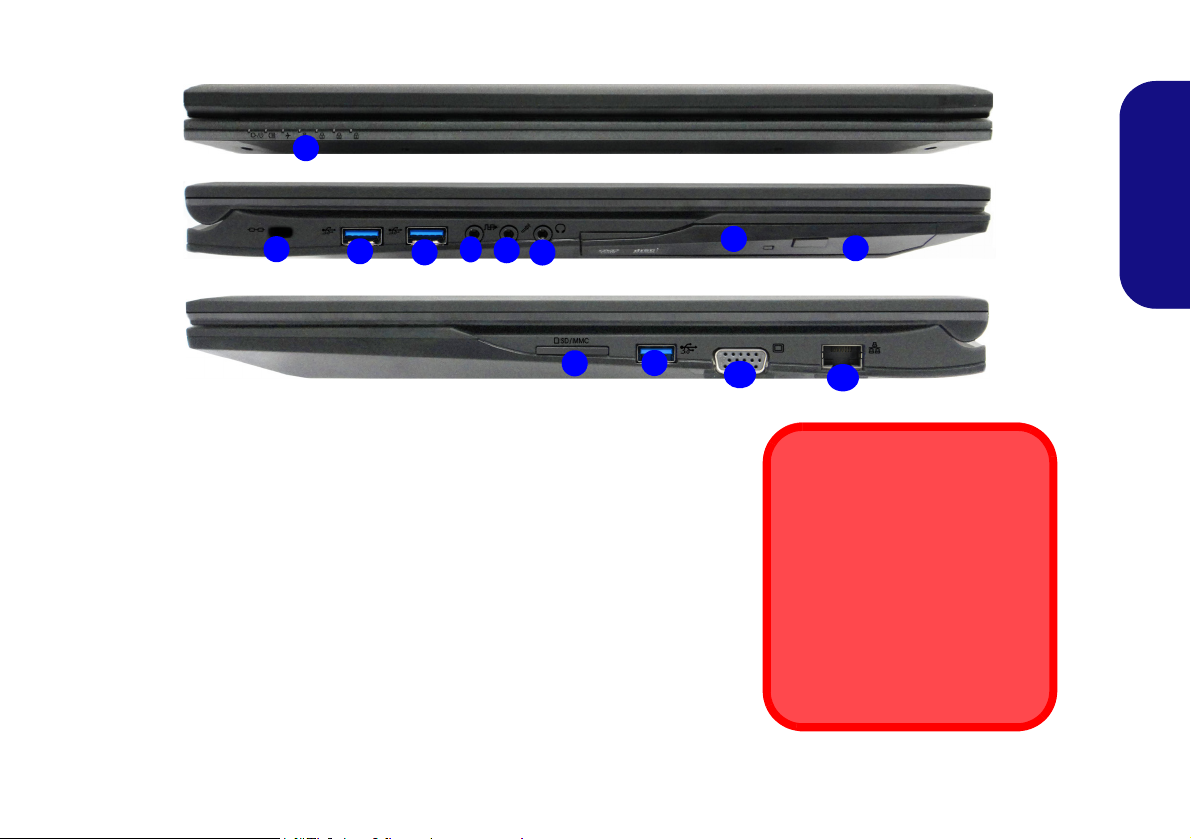
System Map: Front, Left & Right Views (Model B)
3
6
4
5
1
Front
Left
Right
11
7
12
10
2
Figure 13 - Front, Left & Right Views (Model B)
1. LED Indicators
2. Security Lock Slot
3. USB 3.0 Ports
4. S/PDIF-Out Jack
5. Microphone Jack
6. Headphone Jack
7. Optical Device Drive Bay
8. Emergency Eject Hole
(see page 17)
9. USIM Card Reader (for
3G/4G USIM Cards)
10. Multi-in-1 Card Reader
11. External Monitor Port
12. RJ-45 LAN Jack
8
9
3
3
USIM Card Ejection
Simply press on the
USIM card to eject it,
however do not do
this while a connection is in progress.
If you do eject the card
while a 3G/4G connection is ongoing,
you will need to shut
down the system, reinsert the USIM card,
restart the system and
then reestablish the
3G/4G connection.
If you wish to change
USIM cards then you
will also need to shut
down the system, reinsert the USIM card,
restart the system and
then reestablish the
3G/4G connection.
USIM Card
Orientation
Note that the USIM
card’s readable side
(with the gold-colored contacts)
should face upwards
as illustrated.
English
16
System Map: Front, Left & Right Views (Model C)
3
6
4
5
1
Front
Left
Right
10
7
11
2
Figure 14 - Front, Left & Right Views (Model C)
1. LED Indicators
2. Security Lock Slot
3. USB 3.0 Ports
4. S/PDIF-Out Jack
5. Microphone Jack
6. Headphone Jack
7. Optical Device Drive Bay
8. Emergency Eject Hole
9. Multi-in-1 Card Reader
10. External Monitor Port
11. RJ-45 LAN Jack
8
9
3
3
Disc Emergency Eject
If you need to manually eject a
disc (e.g. due to an unexpected
power interruption) you may
push the end of a straightened
paper clip into the emergency
eject hole. Do not use a sharpened pencil or similar object that
may break and become lodged
in the hole.
English
17
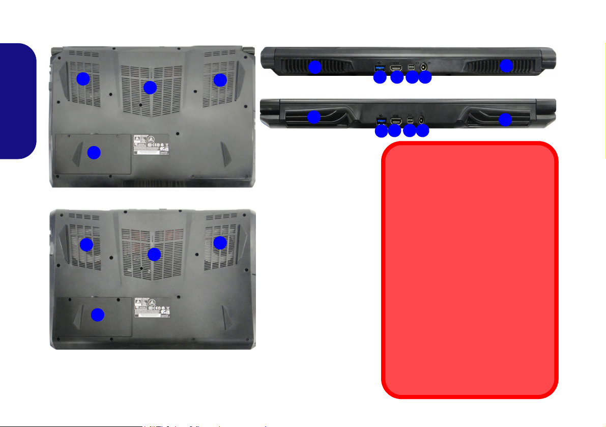
System Map: Bottom & Rear Views (Models A & B)
Figure 15 - Bottom & Rear
Views (Models A & B)
1. Vent
2. Battery
3. USB 3.0 Port
4. HDMI-Out Port
5. Mini DisplayPort
6. DC-In Jack
Overheating
To prevent your computer from overheating make sure nothing blocks any
vent while the computer is in use.
Battery Removal
Note that the built-in battery is not user
removable. Removing the battery will violate the terms of your warranty.
Bottom Cover Removal Warning
Do not remove any cover(s) and/or
screw(s) for the purposes of device upgrade as this may violate the terms of
your warranty.
If you need to replace/remove the hard
disk/RAM/battery etc., for any reason,
please contact your distributor/supplier
for further information.
1
2
1
1
3 4 6
2
1
1
1
Model B
Model A
1
Model A
5
1
Model B
3
4 615
1
English
18
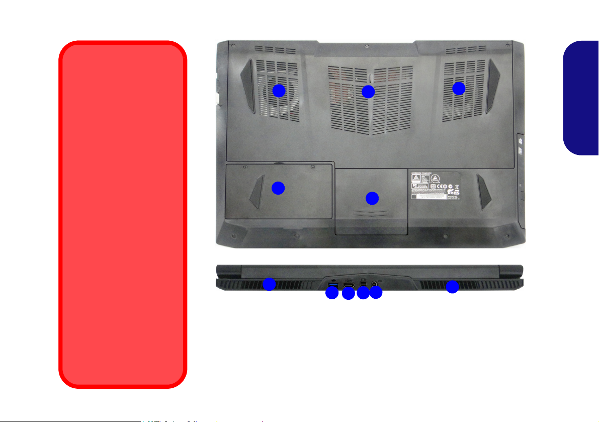
System Map: Bottom & Rear Views (Model C)
1
Overheating
To prevent your computer
from overheating make
sure nothing blocks any
vent while the computer is
in use.
Battery Removal
Note that the built-in battery
is not user removable. Removing the battery will violate the terms of your
warranty.
Bottom Cover Removal
Warning
Do not remove any cover(s)
and/or screw(s) for the purposes of device upgrade as
this may violate the terms of
your warranty.
If you need to replace/remove the hard disk/RAM/
battery etc., for any reason,
please contact your distributor/supplier for further information.
1
1
2
5
Rear
4
6
3
7
Figure 16 - Bottom & Rear Views (Model C)
1. Vent
2. Battery
3. HDD Bay
4. USB 3.0 Port
5. HDMI-Out Port
6. Mini DisplayPort
7. DC-In Jack
1
1
English
19
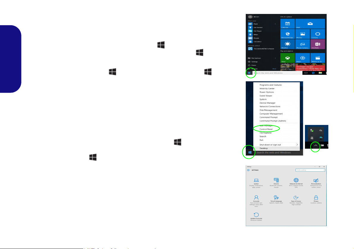
Windows 10 Start Menu, Context Menu, Taskbar, Control Panel and Settings
Most of the apps, control panels, utilities and programs within Windows 10 can be
accessed from the Start Menu by clicking the icon in the taskbar in the lower
left corner of the screen (or by pressing the Windows Logo Key on the keyboard).
Right-click the Start Menu icon (or use the Windows Logo Key + X key
English
combination) to bring up an advanced Context Menu of useful features such as
Control Panel, Programs and Features, Power Options, Task Manager, Search, File
Explorer, Command Prompt, Device Manager and Network Connections etc.
The notification area of the taskbar is in the bottom right of the screen. Some of the
control panels and applications referred to throughout the course of this manual can
be accessed from here.
Throughout this manual you will see an instruction to open the Control Panel. To
access the Control Panel, right-click the Start Menu icon
lower left corner of the screen and select Control Panel from the menu. Or, press
the Windows Logo Key on your keyboard and X to bring up the context menu,
and then press P to bring up the Control Panel.
The Settings item in the Start Menu (and also as an App) gives you quick access
to a number of system settings control panels allowing you to adjust settings for
System, Devices, Network & Internet, Personalization, Accounts, Time & language, Ease of Access, Privacy and Update & security.
in the taskbar in the
20
Figure 17 - Start Menu, Context Menu, Taskbar, Control Panel and Settings

Video Features
The system features both an Intel’s Integrated GPU (for
power-saving) and an NVIDIA’s discrete GPU (for performance). You can switch display devices, and configure
display options, from the Display control panel in Win-
dows as long as the video drivers are installed.
Microsoft Hybrid Graphics
Microsoft Hybrid Graphics is a seamless technology
designed to get best performance from the graphics system while allowing longer battery life, without having to
manually change settings. The computer’s operating system (and some applications) will automatically switch
between the integrated GPUand the discrete GPU when
required by the applications in use.
To access the Display control panel in Windows:
1. Go to the Control Panel.
2. Click Display (icon) - in the Appearances and
Personalization category.
3. Make the required changes from the Display, Resolution,
Orientation or Multiple display menus.
4. Click Apply to save the settings.
To access the Intel® HD Graphics Control Panel:
1. Right-click the desktop and select Graphics Properties from
the menu.
OR
2. Click the icon in the notification area of the Desktop
taskbar and select Graphics Properties from the menu.
To access the NVIDIA Control Panel:
1. Go to the Control Panel.
2. Click NVIDIA Control Panel (icon) - in the Appearances and
Personalization category.
OR
3. Right-click the desktop and select NVIDIA Control Panel from
the menu.
English
21
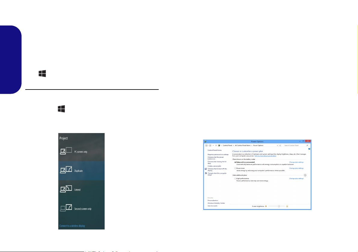
Display Devices
Figure 18
Project
Figure 19 - Power Options
Note that you can use external displays connected to the
HDMI-Out port, external monitor port and/or Mini DisplayPort 1.2. See your display device manual to see which
formats are supported.
In Windows it is possible to quickly configure external
displays from the Project menu (press the Windows Logo
English
Key and the P key).
To configure the displays using the Project menu:
1. Attach your external display device to the appropriate port, and
then turn it on.
2. Press the + P (or Fn + F7) key combination.
3. Click on any one of the options from the menu to select PC
screen only, Duplicate, Extend or Second screen only.
Power Options
The Power Options (Hardware and Sound menu) control panel icon in Windows allows you to configure power
management features for your computer. You can conserve power by means of power plans and configure the
options for the power button, sleep button (Fn + F12),
computer lid (when closed), display and sleep mode (the
default power saving state) from the left menu. Note that
the Power saver plan may have an affect on computer
performance.
Click to select one of the existing plans, or click Create a
power plan in the left menu and select the options to create a new plan. Click Change Plan Settings and click
Change advanced power settings to access further configuration options.
22

Audio Features
Volume Adjustment
The sound volume level can also be set using the volume control within Windows. Click the Speaker icon in
the taskbar to check the setting
.
Sound Blaster Cinema 2 & HDMI/Mini DisplayPort
Note that the Sound Blaster Cinema 2 audio effects do
not apply to audio generated through an HDMI/Mini
DisplayPort connection.
You can configure the audio options on your computer
from the Sound control panel in Windows, or from the
Realtek HD Audio Manager
tion area/control panel (right-click the notification area
icon to bring up an audio menu).
The volume may be adjusted by means of the Fn + F5/F6
key combination.
/ icon in the notifica-
Sound Blaster Cinema 2
Install the Sound Blaster Cinema application to allow
you to configure the audio settings to your requirements
for the best performance in games, music and movies.
English
Sound Blaster Cinema 2 Application
Run the Sound Blaster Cinema control panel from the
notification area of the taskbar. Click on the tabs to access
any of the control panel menus.
Figure 20 - Sound Blaster Cinema 2
(Taskbar Notification Area Icon)
23

Driver Installation General
Guidelines
As a general guide follow the
default on-screen instructions for each driver (e.g.
Next > Next > Finish) unless
you are an advanced user. In
many cases a restart is required to install the driver.
Make sure any modules (e.g.
WLAN or Bluetooth) are ON
before installing the appropriate driver.
Windows Update
After installing all the drivers
make sure you enable Win-
dows Update in order to get
all the latest security updates
etc. (all updates will include
the latest hotfixes from Mi-
crosoft).
Driver Installation & Power
When installing drivers make sure
your computer is powered by the AC/
DC adapter connected to a working
power source. Some drivers draw a
significant amount of power during the
installation procedure, and if the remaining battery capacity is not adequate this may cause the system to
shut down and cause system problems (note that there is no safety issue involved here, and the battery will
be rechargeable within 1 minute).
Figure 21 - Install Drivers
English
Driver Installation
The Device Drivers & Utilities + User’s Manual disc contains the drivers and utilities
necessary for the proper operation of the computer. This setup will probably have already been done for you. If this is not the case, insert the disc and click Install Drivers
(button), or Option Drivers (button) to access the Optional driver menu. Install the
drivers in the order indicated in Figure 21. Click to select the drivers you wish to
install (you should note down the drivers as you install them). Note: If you need to
reinstall any driver, you should uninstall the driver first
Manual Driver Installation
Click the Browse CD/DVD button in the Drivers Installer application and browse to
the executable file in the appropriate driver folder.
If a
Found New Hardware
Cancel, and follow the installation procedure as directed.
wizard appears
during the installation procedure, click
.
24
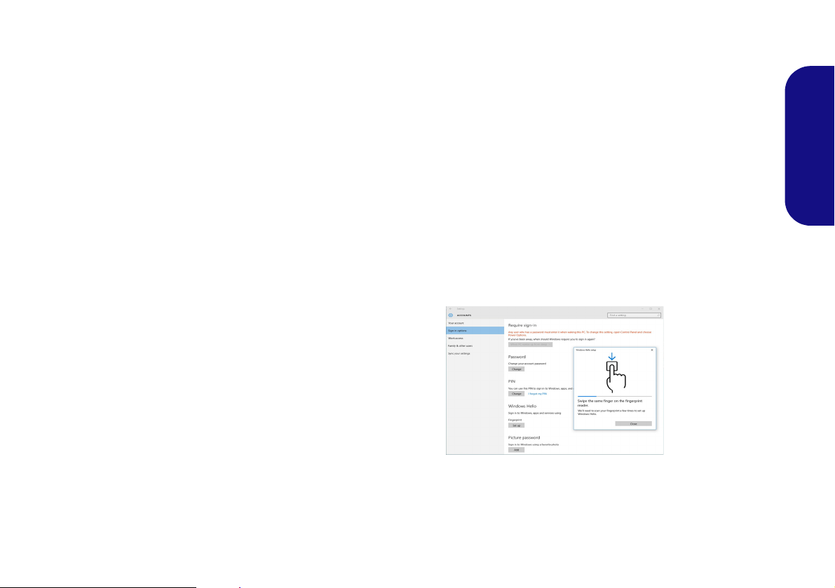
Fingerprint Reader (Option)
Figure 22
Accounts Sign-in op-
tions
Install the driver and enroll your fingerprints as instructed
below before use. The fingerprint reader module uses the
Sign-in options configuration of the Windows Account.
Fingerprint Reader Driver Installation
1. Click Option Drivers (button).
2. Click 2.Install Fingerprint Driver > Yes.
3. Click Next > Install > Finish.
Fingerprint Module Configuration
1. Click the Settings item in the Start Menu.
2. Click Accounts and then click Sign-in options.
3. You will need to add a Windows password (click Add under
Password).
4. After you have added the password you will need to also add a
PIN.
5. Under Windows Hello click Set up under Fingerprint.
6. The wizard will then guide you through the set up process to
scan your fingerprints.
7. You will be instructed to swipe the same finger across the
reader a number of times.
8. Click Close when complete.
9. You can choose to Add another finger (this is recommended)
or Remove the current fingerprint reading.
10. You can now scan your fingerprint to log-on to the computer.
English
25
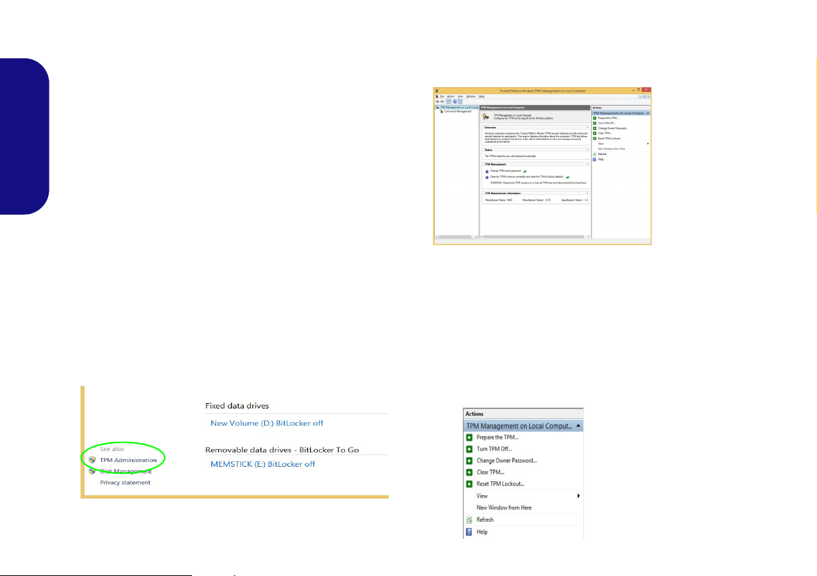
TPM (Option)
Figure 23 - BitLocker Drive Encryption
(TPM Administration)
Figure 24
Trusted Plat-
form Module
(TPM) Manage-
ment on Local
Computer Ad-
ministration
Figure 25
Actions Menu
Before setting up the TPM (Trusted Platform Module)
functions you must initialize the security platform.
Activating TPM
1. Restart the computer.
2. Enter the Aptio Setup Utility pressing F2 during the POST.
3. Use the arrow keys to select the Security menu.
English
4. Select TPM Configuration and press Enter.
5. Press Enter to access the Security Device Support menu and
select Enable.
6. You will then need to press F4 to save the changes and restart
the computer.
4. The TPM Management window allows you to configure the
TPM within Windows. As TPM is usually administered within
large enterprises and organizations, your system administrator
will need to assist you in managing the information here.
TPM Management in Windows
You can manage your TPM settings from within Windows:
1. Go to the Control Panel.
2.
Click
BitLocker Drive Encryption (System and Security).
3. Click TPM Administration.
26
TPM Actions
1. Click Prepare the TPM and follow the instructions in the Wizard
to prepare the TPM (this will probably require a restart of the
computer and confirmation of the setting changes after restart
by pressing the appropriate F key).
2. After the restart the TPM will be prepared and you can then use
the Actions menu to Turn TPM off, Change Owner
Password, Clear TPM or Reset TPM Lockout.
3. A wizard will help take you through any setup steps.
 Loading...