

Clevo M730T, M735T service manual


Notebook Computer
M730T/M735T
Service Manual
Preface
Preface
I

Preface
Preface
Notice
The company reserves the right to revise this publication or to change its contents without notice. Information contained
herein is for reference only and does not constitute a commitment on the part of the manufacturer or any subsequent vendor. They assume no responsibility or liability for any errors or inaccuracies that may appear in this publication nor are
they in anyway responsible for any loss or damage resulting from the use (or misuse) of this publication.
This publication and any accompanying software may not, in whole or in part, be reproduced, translated, transmitted or
reduced to any machine readable form without prior consent from the vendor, manufacturer or creators of this publication, except for copies kept by the user for backup purposes.
Brand and product names mentioned in this publication may or may not be copyrights and/or registered trademarks of
their respective companies. They are mentioned for identification purposes only and are not intended as an endorsement
of that product or its manufacturer.
Version 3.0
January 2009
Trademarks
Intel, Celeron and Intel Core are trademarks of Advanced Micro Devices, Inc.
Windows® is a registered trademark of Microsoft Corporation.
Other brand and product names are trademarks and./or registered trademarks of their respective companies.
II

About this Manual
This manual is intended for service personnel who have completed sufficient training to undertake the maintenance and
inspection of personal computers.
It is organized to allow you to look up basic information for servicing and/or upgrading components of the M730T/
M735T series notebook PC.
The following information is included:
Chapter 1, Introduction, provides general information about the location of system elements and their specifications.
Chapter 2, Disassembly, provides step-by-step instructions for disassembling parts and subsystems and how to upgrade
elements of the system.
Preface
Appendix A, Part Lists
Appendix B, Schematic Diagrams
Appendix C, Updating the FLASH ROM BIOS
Preface
III

Preface
Preface
Warning
Use only shielded cables to connect I/O devices to this
equipment. You are
cautioned that changes or modifications not
expressly approved by
the manufacturer for
compliance with the
above standards could
void your authority to
operate the equipment.
If your purchase option
includes both Wire-
less LAN and 3.5G
modules, then the appropriate antennas will
be installed. Note that
In order to comply with
FCC RF exposure
compliance requirements, the antenna
must not be co-located
or operate in conjunction with any other antenna or transmitter.
FCC Statement
(Federal Communications Commission)
You are cautioned that changes or modifications not expressly approved by the party responsible for compliance could
void the user's authority to operate the equipment.
This equipment has been tested and found to comply with the limits for a Class B digital device, pursuant to Part 15 of
the FCC Rules. These limits are designed to provide reasonable protection against harmful interference in a residential
installation. This equipment generates, uses and can radiate radio frequency energy and, if not installed and used in accordance with the instructions, may cause harmful interference to radio communications. However, there is no guarantee
that interference will not occur in a particular installation. If this equipment does cause harmful interference to radio or
television reception, which can be determined by turning the equipment off and on, the user is encouraged to try to correct
the interference by one or more of the following measures:
• Re orient or relocate the receiving antenna.
• Increase the separation between the equipment and receiver.
• Connect the equipment into an outlet on a circuit different from that to which the receiver is connected.
• Consult the service representative or an experienced radio/TV technician for help.
Operation is subject to the following two conditions:
1. This device may not cause interference.
And
2. This device must accept any interference, including interference that may cause undesired operation of the device.
FCC RF Radiation Exposure Statement:
1. This Transmitter must not be co-located or operating in conjunction with any other antenna or transmitter.
2. This equipment complies with FCC RF radiation exposure limits set forth for an uncontrolled environment. This equipment
should be installed and operated with a minimum distance of 20 centimeters between the radiator and you body.
IV

IMPORTANT SAFETY INSTRUCTIONS
Follow basic safety precautions, including those listed below, to reduce the risk of fire, electric shock and injury to persons when using any electrical equipment:
1. Do not use this product near water, for example near a bath tub, wash bowl, kitchen sink or laundry tub, in a wet
basement or near a swimming pool.
2. Avoid using a telephone (other than a cordless t ype) durin g an electrical sto r m. There may be a re mote risk of electrical shock from lightning.
3. Do not use the telephone to report a gas leak in the vicinity of the leak.
4. Use only the power cord and batteries indicated in this manual. Do not dispose of batteries in a fire. They may
explode. Check with local codes for possible special disposal instructions.
5. This product is intended to be supplied by a Listed Power Unit (DC Output 19V, 3.42A OR 18.5V, 3.5A (65W) minimum AC/DC Adapter).
CAUTION
Always disconnect all telephone lines from the wall outlet before servicing or disassembling this equipment.
Preface
Preface
TO REDUCE THE RISK OF FIRE, USE ONLY NO. 26 AWG OR LARGER,
TELECOMMUNICATION LINE CORD
This Computer’s Optical Device is a Laser Class 1 Product
V
Preface
Instructions for Care and Operation
The notebook computer is quite rugged, but it can be damaged. To prevent this, follow these suggestions:
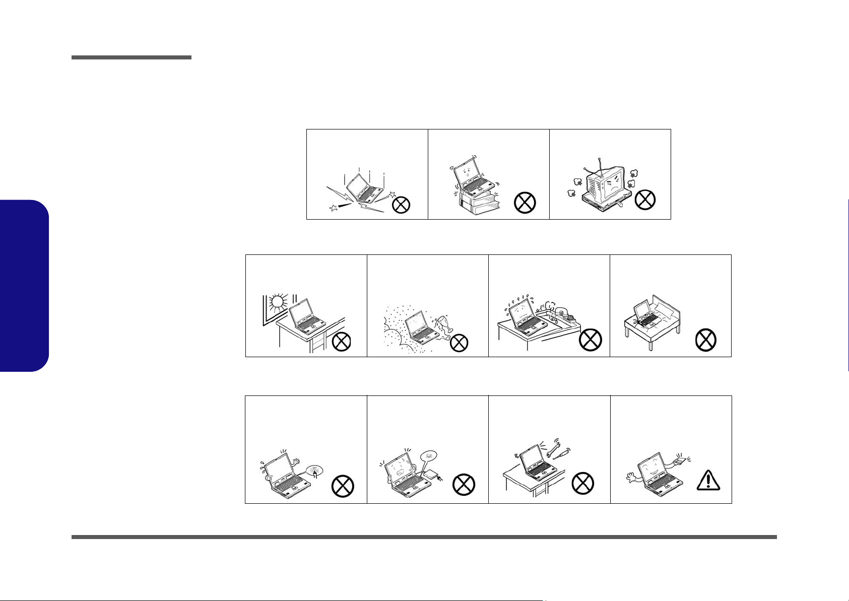
1. Don’t drop it, or expose it to shock. If the computer falls, the case and the components could be damaged.
Preface
Do not expose the computer
to any shock or vibration.
Do not place it on an unstable
surface.
Do not place anything heavy
on the computer.
2. Keep it dry, and don’t overheat it. Keep the computer and power supply away from any kind of heating element. This
is an electrical appliance. If water or any other liquid gets into it, the computer could be badly damaged.
Do not expose it to excessive
heat or direct sunlight.
Do not leave it in a place
where foreign matter or moisture may affect the system.
Don’t use or store the computer in a humid environment.
Do not place the computer on
any surface which will block
the vents.
3. Follow the proper working procedures for the computer. Shut the computer down properly and don’t forget to save
your work. Remember to periodically save your data as data may be lost if the battery is depleted.
Do not turn off the power
until you properly shut down
all programs.
Do not turn off any peripheral
devices when the computer is
on.
Do not disassemble the computer by yourself.
Perform routine maintenance
on your computer.
VI
4. Avoid interference. Keep the computer away from high capacity transformers, electric motors, and other strong magnetic fields. These can hinder proper performance and damage your data.
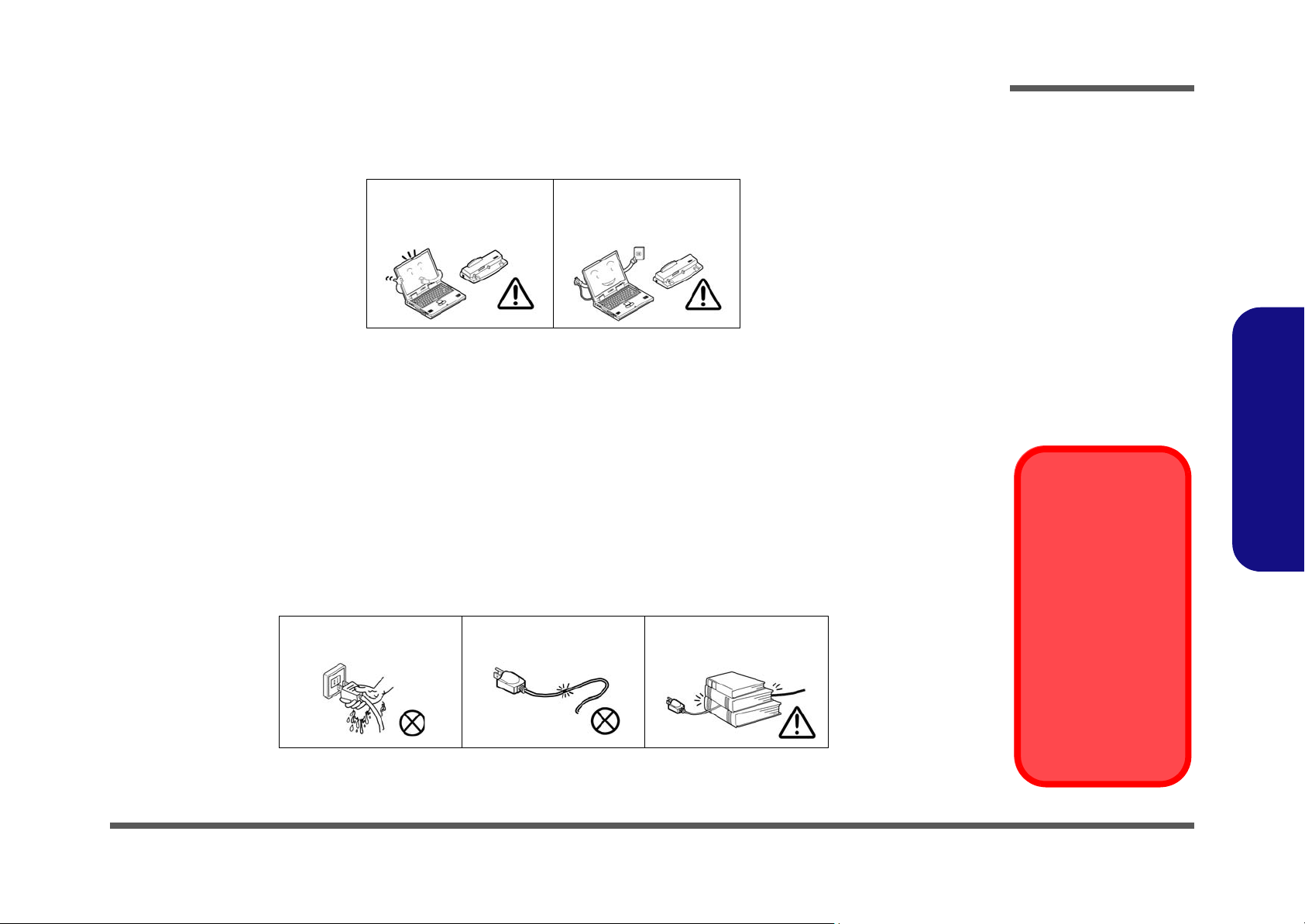
5. Take care when using peripheral devices.
Preface
Use only approved brands of
peripherals.
Unplug the power cord befor e
attaching peripheral devices.
Power Safety
The computer has specific power requirements:
• Only use a power adapter approved for use with this computer.
• Your AC adapter may be designed for international travel but it still requires a steady, uninterrupted power supply. If you are
unsure of your local power specifications, consult your service representative or local power company.
• The power adapter may have either a 2-prong or a 3-prong ground ed plug. The third prong is an important safety feature; do
not defeat its purpose. If you do not have access to a compatible outlet, have a qualified electrician install one.
• When you want to unplug the power cord, be sure to disconne ct it by the plug head, not by its wire.
• Make sure the socket and any extension cord(s) you use can support the total current load of all the connected devices.
• Before cleaning the computer, make sure it is disconnected from any external power supplies.
Do not plug in the power
cord if you are wet.
Do not use the power cord if
it is broken.
Do not place heavy objects
on the power cord.
Preface
Power Safety
Warning
Before you undertake
any upgrade procedures, make sure that
you have turned off the
power, and disconnected all peripherals
and cables (including
telephone lines). It is
advisable to also remove your battery in
order to prevent accidentally turning the
machine on.
VII

Preface
Preface
Battery Precautions
• Only use batteries designed for this computer. The wrong battery type may explode, leak or damage the computer.
• Do not remove any batteries from the computer while it is po wered on.
• Do not continue to use a battery that has been dropped, or that appears damaged (e.g. bent or twisted) in any way. Even if the
computer continues to work with a damaged battery in place, it may cause circuit damage, which may possibly result in fire.
• Recharge the batteries using the notebook’s system. Incorrect recharging may make the battery explode.
• Do not try to repair a battery pack. Refer any battery pack repair or replacement to your service representative or qualified service
personnel.
• Keep children away from, and promptly dispose of a damaged battery. Always dispose of batteries carefully. Batteries may explode
or leak if exposed to fire, or improperly handled or discarded.
• Keep the battery away from metal appliances.
• Affix tape to the battery contacts before disposing of the battery.
• Do not touch the battery contacts with your hands or metal objects.
Battery Disposal
The product that you have purchased contains a rechargeable b attery. The battery is recycl able. At the end of
its useful life, under various state and local laws, it may be illegal to dispose of this battery into the municipal
waste stream. Check with your local solid waste officials for details i n your area for recycling options or p roper
disposal.
VIII
Caution
Danger of explosion if battery is incorrectly replaced. Replace only with the same or equivalent type recommended by the manufacturer. Discard used battery according to the manufacturer’s instructions.
Related Documents
You may also need to consult the following manual for additional information:
User’s Manual on CD
This describes the notebook PC’s features and the procedures for operating the computer and its ROM-based setup program. It also describes the installation and operation of the utility programs provided with the notebook PC.

Contents
Preface
Introduction ..............................................1-1
Overview .........................................................................................1-1
System Specifications .....................................................................1-2
External Locator - Top View with LCD Panel Open ......................1-5
External Locator - Front & Right side Views .................................1-6
External Locator - Left Side & Rear View .....................................1-7
External Locator - Bottom View .....................................................1-8
Mainboard Overview - Top (Key Parts) .........................................1-9
Mainboard Overview - Bottom (Key Parts) ..................................1-10
Mainboard Overview - Top (Connectors) .....................................1-11
Mainboard Overview - Bottom (Connectors) ...............................1-12
Disassembly ...............................................2-1
Overview .........................................................................................2-1
Maintenance Tools ..........................................................................2-2
Connections .....................................................................................2-2
Maintenance Precautions .................................................................2-3
Disassembly Steps ...........................................................................2-4
Removing the Battery ......................................................................2-5
Removing the Hard Disk Drive .......................................................2-6
Removing the Optical (CD/DVD) Device ......................................2-8
Removing the System Memory (RAM) ..........................................2-9
Removing the Inverter Board ........................................................2-11
Removing the Processor ................................................................2-12
Removing the Wireless LAN Module ...........................................2-14
Removing the Bluetooth Module ..................................................2-15
Removing the Keyboard ................................................................2-16
Removing the Modem ...................................................................2-17
Part Lists ..................................................A-1
Part List Illustration Location ........................................................A-2
Top with Fingerprint (M730T) ...................................................... A-3
Top without Fingerprint (M730T) ................................................. A-4
Bottom (M730T) ............................................................................ A-5
LCD (M730T) ................................................................................ A-6
HDD (M730T) ............................................................................... A-7
COMBO (M730T) ......................................................................... A-8
DVD-Dual Drive (M730T) ............................................................ A-9
Top with Fingerprint (M735T) .................................................... A-10
Top without Fingerprint (M735T) ............................................... A-11
Bottom (M735T) .......................................................................... A-12
LCD 1 (M735T) ........................................................................... A-13
LCD 2 (M735T) ........................................................................... A-14
HDD (M735T) ............................................................................. A-15
COMBO (M735T) ....................................................................... A-16
DVD-Dual Drive (M735T) .......................................................... A-17
Schematic Diagrams.................................B-1
System Block Diagram ...................................................................B-2
Intel Penryn (Socket-P) 1/2 ............................................................B-3
Intel Penryn (Socket-P) 2/2 ............................................................B-4
Cantiga 1/6 - Host ...........................................................................B-5
Cantiga 2/6 - VGA, CRT ................................................................B-6
Cantiga 3/6 - DDR ..........................................................................B-7
Cantiga 4/6 - Power ........................................................................B-8
Cantiga 5/6 - Power ........................................................................B-9
Cantiga 6/6 - GND ........................................................................B-10
DDRII CHANNEL A ...................................................................B-11
DDRII CHANNEL B ...................................................................B-12
Panel, Inverter, CRT .....................................................................B-13
ICH9-M 1/5 - SATA .....................................................................B-14
ICH9-M 2/5 - PCIE, PCI, USB ....................................................B-15
Preface
IX

Preface
ICH9-M 3/5 - GPIO, PWR Management ....................................B-16
ICH9-M 4/5 - Power .................................................................... B-17
ICH9-M 5/5 - GND ......................................................................B-18
Clock Generator ...........................................................................B-19
Multi I/O, ODD, CCD, BT, TPM ................................................ B-20
New Card, Mini PCIE .................................................................. B-21
LED, FAN, TP, FP, USB ............................................................. B-22
JMB385 Card Reader ...................................................................B-23
PCI-E LAN RTL8111C ............................................................... B-24
Audio Codec ALC662 .................................................................. B-25
Audio AMP2056 .......................................................................... B-26
KBC-ITE IT8512E ....................................................................... B-27
System Power, LED BKLT .......................................................... B-28
Power VDD3, VDD5 ................................................................... B-29
Power 1.5VS, 1.05VS, 3.3V, 5V .................................................. B-30
Power 1.8V, 0.9VSM ................................................................... B-31
Preface
Power VCORE ............................................................................. B-32
Power AC-IN, Charger ................................................................. B-33
Multi I/O Board 1/2 ......................................................................B-34
Multi I/O Board 2/2 ......................................................................B-35
Finger Printer Board .....................................................................B-36
Click Board .................................................................................. B-37
M730T ODD Bridge Board ..........................................................B-38
M730T Audio Board .................................................................... B-39
Power Sequence Diagram ............................................................ B-40
Power Sequence v3.0 ................................................................... B-41
Use the flash tools to update the BIOS ........................................... 2-2
Restart the computer (booting from the HDD) ............................... 2-2
Updating the FLASH ROM BIOS......... C-1
Download the BIOS ........................................................................2-1
Unzip the downloaded files to a bootable CD/DVD/ or USB Flash
drive ................................................................................................. 2-1
Set the computer to boot from the external drive ............................2-1
X

Chapter 1: Introduction
Overview
This manual covers the information you need to service or upgrade the M730T/M735T series notebook computer. Information about operating the computer (e.g. getting started, and the Setup utility) is in the User’s Manual. Information
about drivers (e.g. VGA & audio) is also found in User’s Manual. That manual is shipped with the computer.
Operating systems (e.g. Windows XP, Windows Vista, etc.) have their own manuals as do application software (e.g. word
processing and database programs). If you have questions about those programs, you should consult those manuals.
Introduction
The M730T/M735T series notebook is designed to be upgradeable. See “Disassembly” on page 2 - 1 for a detailed description of the upgrade procedures for each specific component. Please note the warning and safety information indicated by the “” symbol.
The balance of this chapter reviews the computer’s technical specifications and features.
1.Introduction
Overview 1 - 1

Introduction
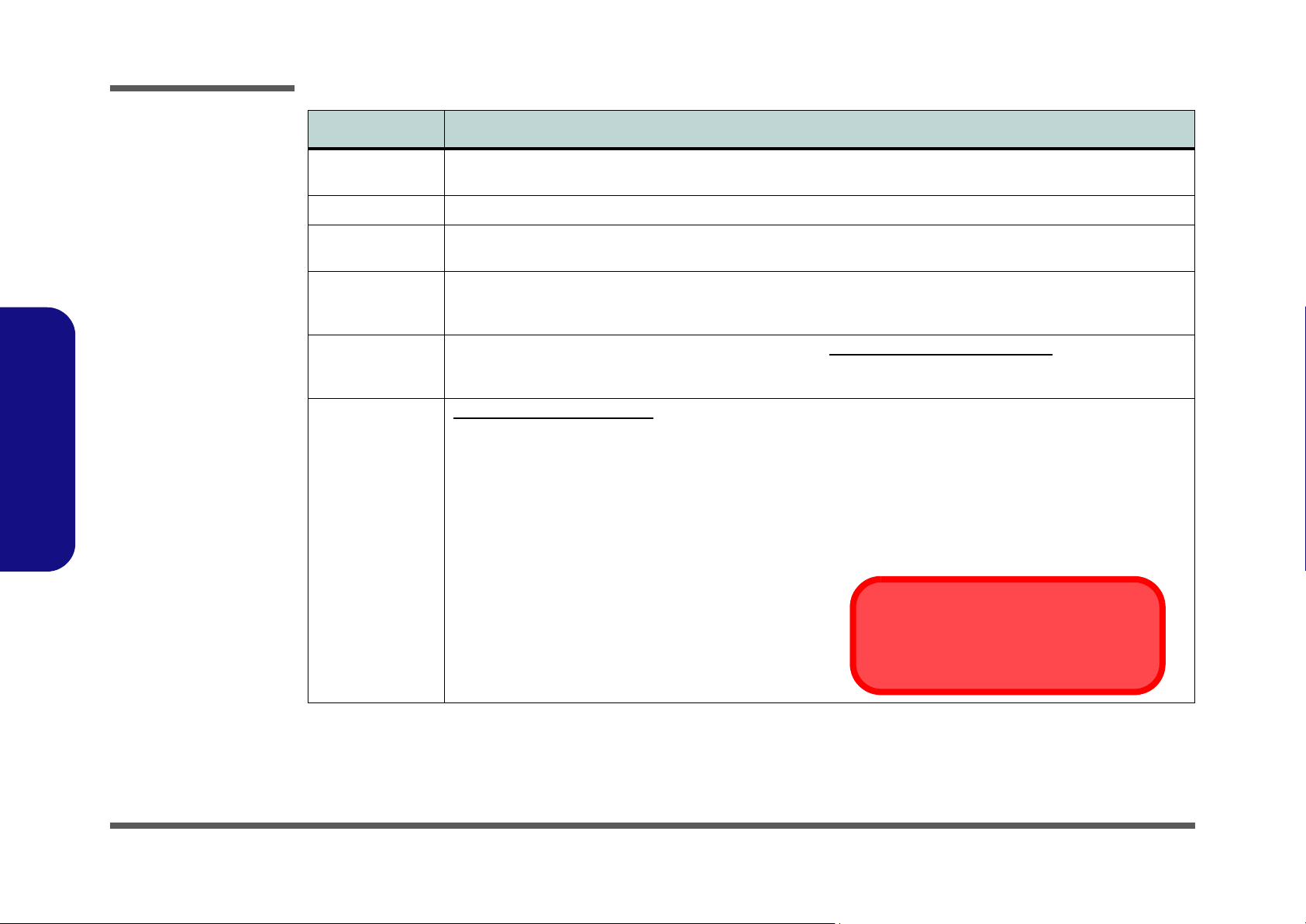
System Specifications
Feature Specification
1.Introduction
Processor Intel® Core™2 Duo Processor
35W - (478-pin) Micro-FC-PGA Package - Socket-P
T9400/ T9600
Intel® Core™2 Duo Processor
25W - (478-pin) Micro-FC-PGA Package - Socket-P
P9500
Intel® Core™2 Duo Processor
25W - (478-pin) Micro-FC-PGA Package - Socket-P
P8400/ P8600
Core Logic Intel GM45 + ICH9M Chipset
LCD 13.3" WXGA (1280 * 800) TFT LCD LCD with LED Backlight (Option)
Memory 64-bit Wide DDRII (DDR2) Data Channel
Supports Dual Channel DDRII (DDR2) SDRAM
Two 200 Pin SO-DIMM Sockets Supporting DDRII (DDR2) 667MHz/800MHz RAM Modules
Memory Expandable up to 4GB (1024/2048 MB DDR2 Modules)
Intel Turbo Memory (Robson) NAND Flash 2G Memory Card Module (Factory Option)
Video Adapter Intel GM45 Integrated Video
High Preference 3D/2D Graphic Accelerator
Supports Dynamic Video Memory Technology DVMT (up to 256MB dynamically allocated from system memory where
needed)
Supports DirectX10 3D Graphics Engine Accelerator
45nm (45 Nanometer) Process Technology
6MB On-die L2 Cache & 1006MHz FSB
2.53/ 2.8 GHz
45nm (45 Nanometer) Process Technology
6MB On-die L2 Cache & 1066MHz FSB
2.53 GHz
45nm (45 Nanometer) Process Technology
3MB On-die L2 Cache & 1006MHz FSB
2.4/ 2.53 GHz
Security Security (Kensington® Type) Lock Slot
BIOS One 32Mb SPI Flash ROM Phoenix™ BIOS
Storage One Changeable 12.7mm(h) SATA (Serial) Optical Device (CD/DVD) Type Drive (see “Optional” on page 1 - 4)
1 - 2 System Specifications
Fingerprint ID Reader Module (Factory Option)
Easy Changeable 2.5" 9.5 mm (h) SATA (Serial) HDD
BIOS Password
Trusted Platform Module

Feature Specification
Introduction
Audio High Definition Audio (HDA)
Compliant with Microsoft UAA (Universal Audio
Architecture)
Keyboard &
Pointing Device
Interface Three USB 2.0 Ports
Card Reader Embedded 7-in-1 Card Reader (MS/ MS Pro/ SD/ Mini SD/ MMC/ RS MMC/ MS Duo)
ExpressCard Slot One ExpressCard/34(54) Slot
Mini-Card Slots
Communication
Note:
*2.0M Pixel PC
Camera Module and
Intel WiFi Link 5300
Series
not available for
computers with
LED backlight.
**The 3.5G and Intel Turbo Memory
Modules cannot co-
exist. There is only
one slot available for
either of these factory option modules.
Option are
Winkey Keyboard Built-In TouchPad with Scrolling Function
One Headphone-Out Jack
One Microphone-In Jack
One S/PDIF Out Jack
One Internal Microphone
Note: MS Duo/ Mini SD/ RS MMC Cards require a PC adapter
One Mini-Card Slot for
One Mini-Card Slot for
10M/ 100/ 1000Mb Base-TX Ethernet LAN
Azalia 56K Modem V.90 & V.92 Compliant
Intel® WiFi Link 5300 Series (3*3 - 802.11a/g/n) Wireless LAN Mini-Card Module (
Intel® WiFi Link 5100 Series (1*2 - 802.11a/g/n) Wireless LAN Mini-Card Module (
3rd Party 802.11b/g Wireless LAN Mini-Card Module with USB interface (Option)
Bluetooth 2.0 + EDR (Enhanced Data Rate) Module (Factory Option)
*1.3M or 2.0M Pixel PC Camera Module with USB interface (Factory Option)
3.5G Module
**UMTS/HSPDA-based 3.5G Mini-Card Module with USB Interface (Factory Option)
Quad-band GSM/GPRS (850 MHz, 900 MHz, 1800 MHz, 1900 MHz)
UMTS WCDMA FDD (2100 MHz)
(see sidebar):
Wireless LAN Module
3.5G Module OR Turbo Memory Module
UMTS Modes
Note that UMTS modes CAN NOT be used in North America.
Direct Sound 3D™ Compatible
2 * Built-In Speakers
Built-In Microphone
One RJ-11 Modem Jack
One RJ-45 LAN Jack
One DC-In Jack
One External Monitor Port
Option
Option
1.Introduction
)
)
System Specifications 1 - 3
Introduction
Feature Specification
1.Introduction
Power
Management
Power
Battery 4 Cell Smart Lithium-Ion Battery Pack, 14.8V/2.4AH
Environmental
Spec
Dimensions
& Weight
Optional
Note:
*2.0M Pixel PC
Camera Module and
Intel WiFi Link 5300
Series
not available for
computers with
LED backlight.
**The 3.5G and Intel Turbo Memory
Modules cannot co-
exist. There is only
one slot available for
either of these factory option modules.
Option are
Supports ACPI 3.0 Supports Wake on LAN
Full Range AC/DC Adapter AC Input 100 - 240V, DC Output 50 - 60Hz, 19V, 3.42A or 18.5V, 3.5A (65 Watts)
8 Cell Smart Lithium-Ion Battery Pack, 14.8V/4.4AH (Option)
Temperature
Operating: 5
Non-Operating: -20°C - 60°C
310mm (w) * 233mm (d) * 30-36mm (h)
2.0 kg With 4 Cell Battery and ODD
Optical Drive Module Options:
SATA DVD/CD-RW Combo Drive Module
SATA DVD Dual (Super Multi) Drive Module
Intel® WiFi Link 5300 Series (3*3 - 802.11a/g/n) Wireless
LAN Mini-Card Module
Intel® WiFi Link 5100 Series (1*2 - 802.11a/g/n) Wireless
LAN Mini-Card Module
3rd Party 802.11b/g Wireless LAN Mini-Card Module with
USB interface
8 Cell Smart Lithium-Ion Battery Pack
*1.3M or 2.0M Pixel USB PC Camera Module (Factory
Option)
Bluetooth 2.0 + EDR (Enhanced Data Rate) Module
(Factory Option)
°C - 35°C
Supports Resume from Modem Ring
Relative Humidity
Operating: 20% - 80%
Non-Operating: 10% - 90%
Optional LCD with LED Backlight:
310mm (w) * 233mm (d) * 18-31mm (h)
1.8 kg With 4 Cell Battery and ODD
Fingerprint ID Reader Module (Factory Option)
*Intel Turbo Memory (Robson) NAND Flash Memory
Card Module (Factory Option)
OR
**UMTS/HSPDA-based 3.5G Module with Mini Card
Interface (Factory Option)
Quad-band GSM/GPRS (850 MHz, 900 MHz, 1800
MHz, 1900 MHz)
UMTS WCDMA FDD (2100 MHz)
UMTS Modes
Note that UMTS modes CAN NOT be used in
North America.
1 - 4 System Specifications
Introduction
External Locator - Top View with LCD Panel Open
1
2
4
5
3
9
6
6
7
8
10
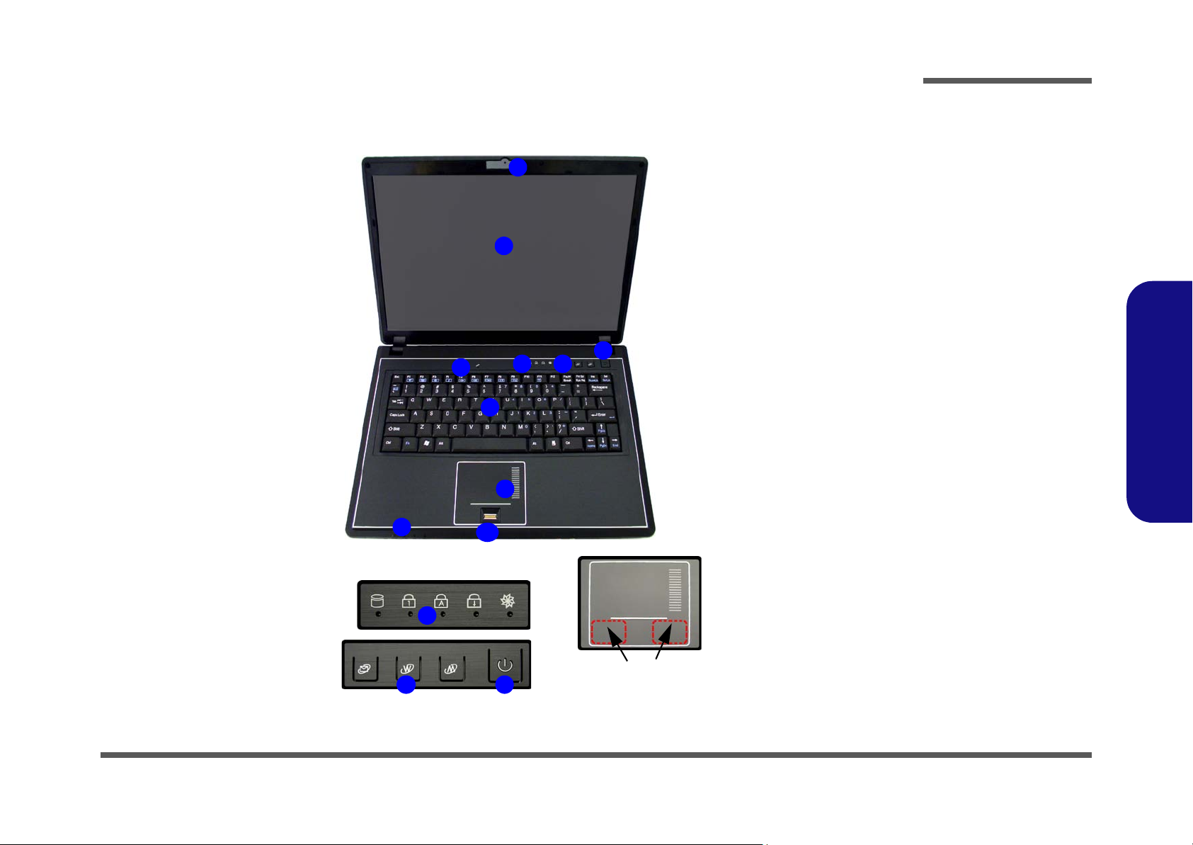
Figure 1
Top View
1. Optional Built-In
PC Camera
2. LCD
3. Built-In
Microphone
4. Power Button
5. Hot Key Buttons
6. LED Status
Indicators
7. Keyboard
8. Touchpad &
Buttons
9. LED Power &
Communication
Indicators
10.Fingerprint
(Optional)
*Note: This model may have
either a fingerprint module or
card reader module, depending on your purchase configuration.
1.Introduction
5 4
Touchpad Buttons
(valid operation area)
External Locator - Top View with LCD Panel Open 1 - 5

Introduction
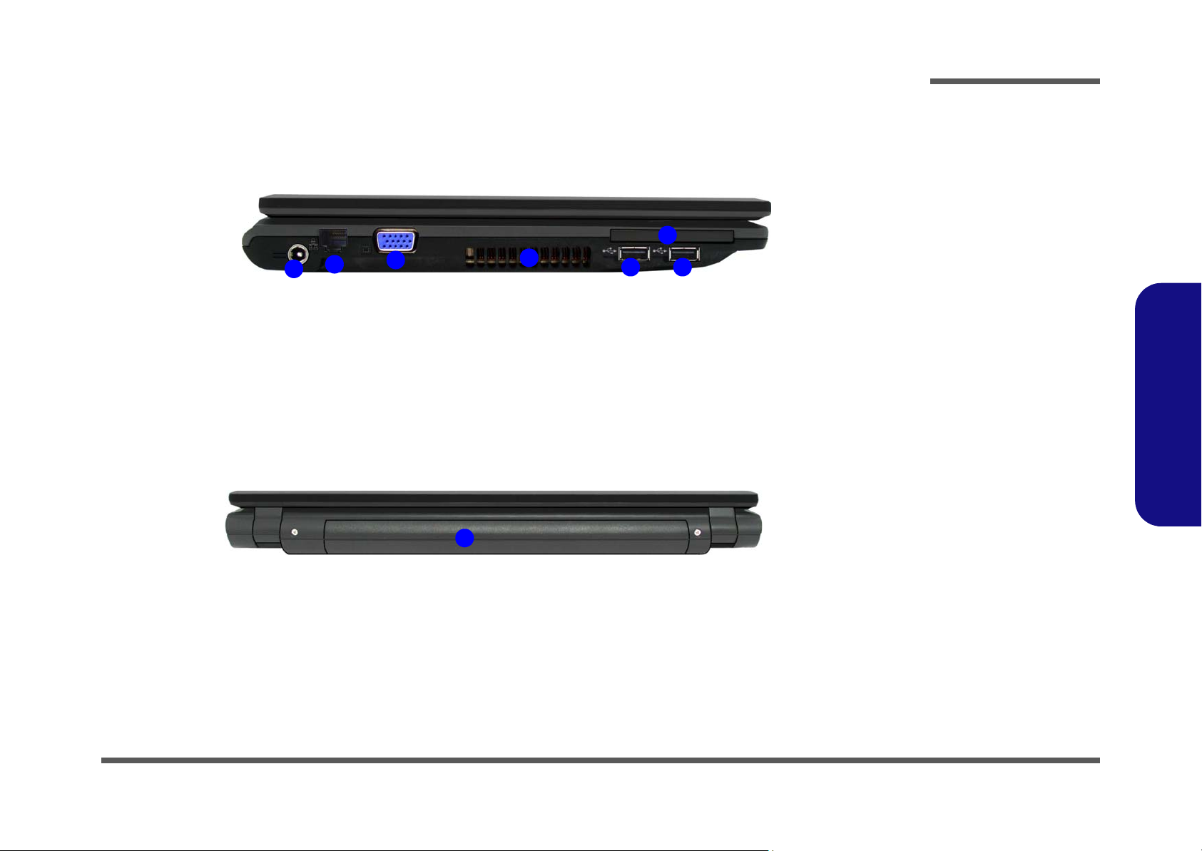
Figure 2
Front Views
1. LED Power &
Communication
Indicators
2. 7-in-1 Card
Reader
3. S/PDIF-Out Jack
4. Microphone-In
Jack
5. Headphone-Out
Jack
Figure 3
1.Introduction
Right Side Views
1. Optical Device
Drive Bay
2. USB 2.0 Port
3. RJ-11 Phone
Jack
4. Security Lock
Slot
External Locator - Front & Right side Views
1
2
1
43 5
2
3
4
1 - 6 External Locator - Front & Right side Views
External Locator - Left Side & Rear View
2
1
3
4
Introduction
Figure 4
Left Side View
1. DC-In Jack
2. RJ-45 LAN Jack
3. External Monitor
6
55
Port
4. Vent/Fan Intake/
Outlet
5. 2 * USB 2.0 Ports
6. ExpressCard Slot
1.Introduction
1
1. Battery
Figure 5
Rear View
External Locator - Left Side & Rear View 1 - 7
Introduction
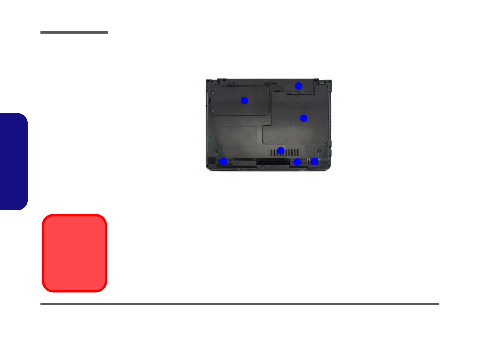
Figure 6
Bottom View
External Locator - Bottom View
1. Battery (4 Cell
Battery Pictured)
2. Hard Disk Bay
Cover
(3.5G Module
Location)
3. RAM & CPU Bay
Cover
4. Vent/Fan Intake/
Outlet
5. Speakers
1.Introduction
Overheating
1
2
3
4
5
5
4
To prevent your computer from overheating
make sure nothing
blocks the vent/fan intakes while the computer is in use.
1 - 8 External Locator - Bottom View
Introduction
Mainboard Overview - Top (Key Parts)
1
2
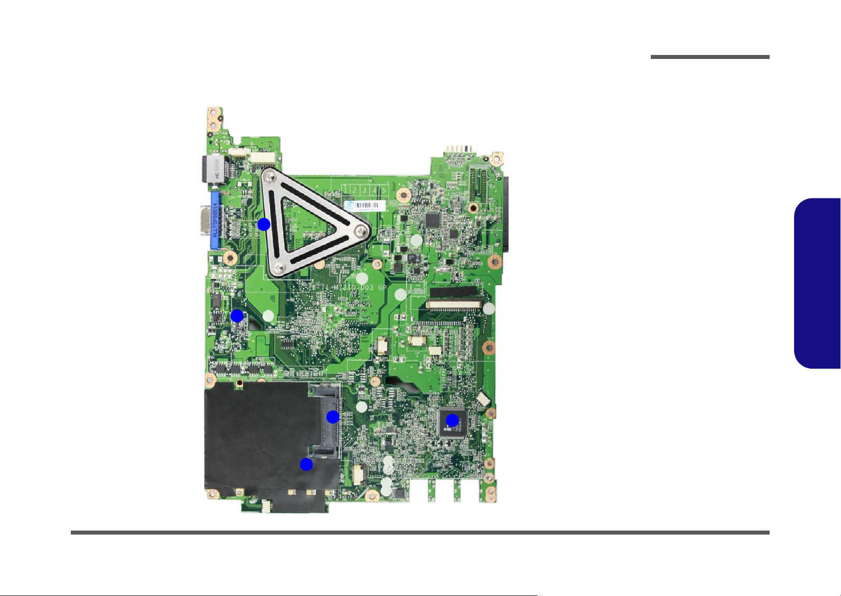
Figure 7
Mainboard Top
Key Parts
1. Transformer
2. RTL61 11C
3. ExpressCard
Connector
4. JMB385
5. KBC ITE IT8502E
1.Introduction
3
4
5
Mainboard Overview - Top (Key Parts) 1 - 9
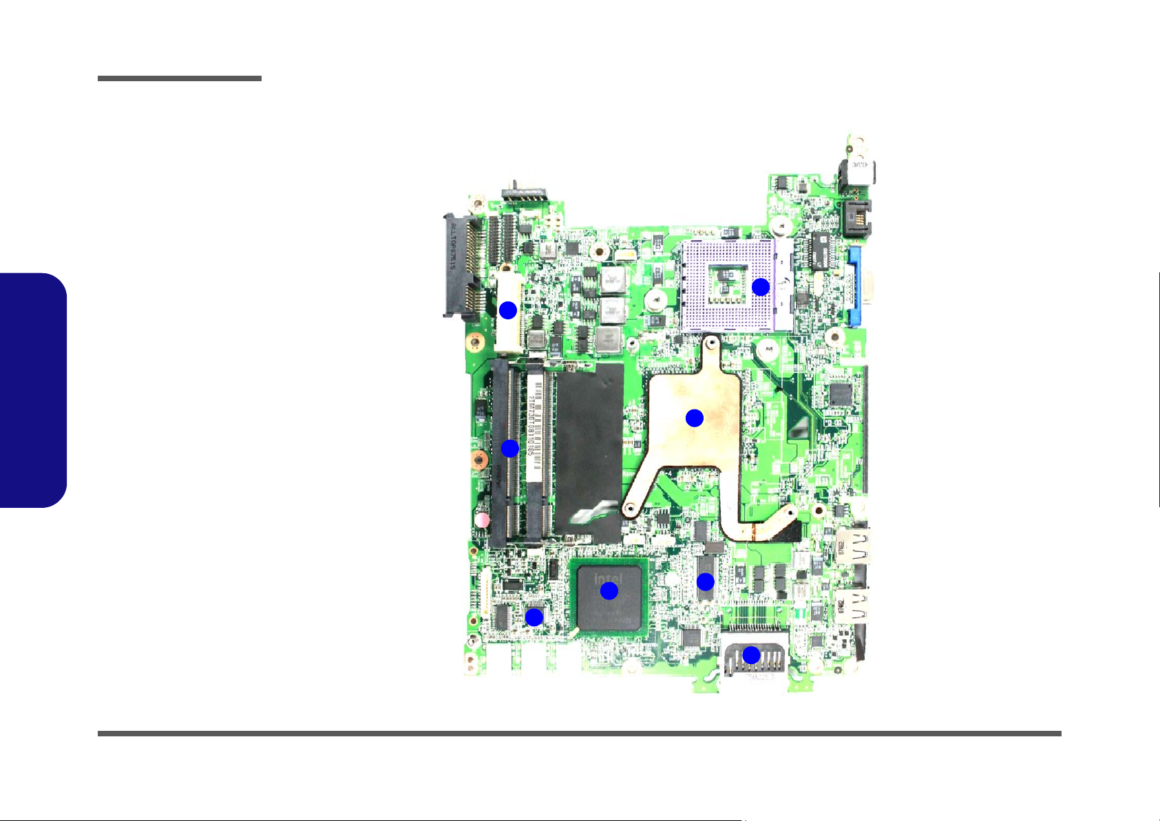
Introduction
Figure 8
Mainboard Bottom
Key Parts
1. CPU Socket (no
CPU installed)
2. Northbridge
3. Memory Slots
DDR2 SO-DIMM
4. ICS
5. Card Reader
Socket
6. Southbridge
7. Audio Codec
8. Mini-Card
Connector (WLAN
Module)
1.Introduction
Mainboard Overview - Bottom (Key Parts)
1
8
2
3
1 - 10 Mainboard Overview - Bottom (Key Parts)
6
7
4
5
Introduction
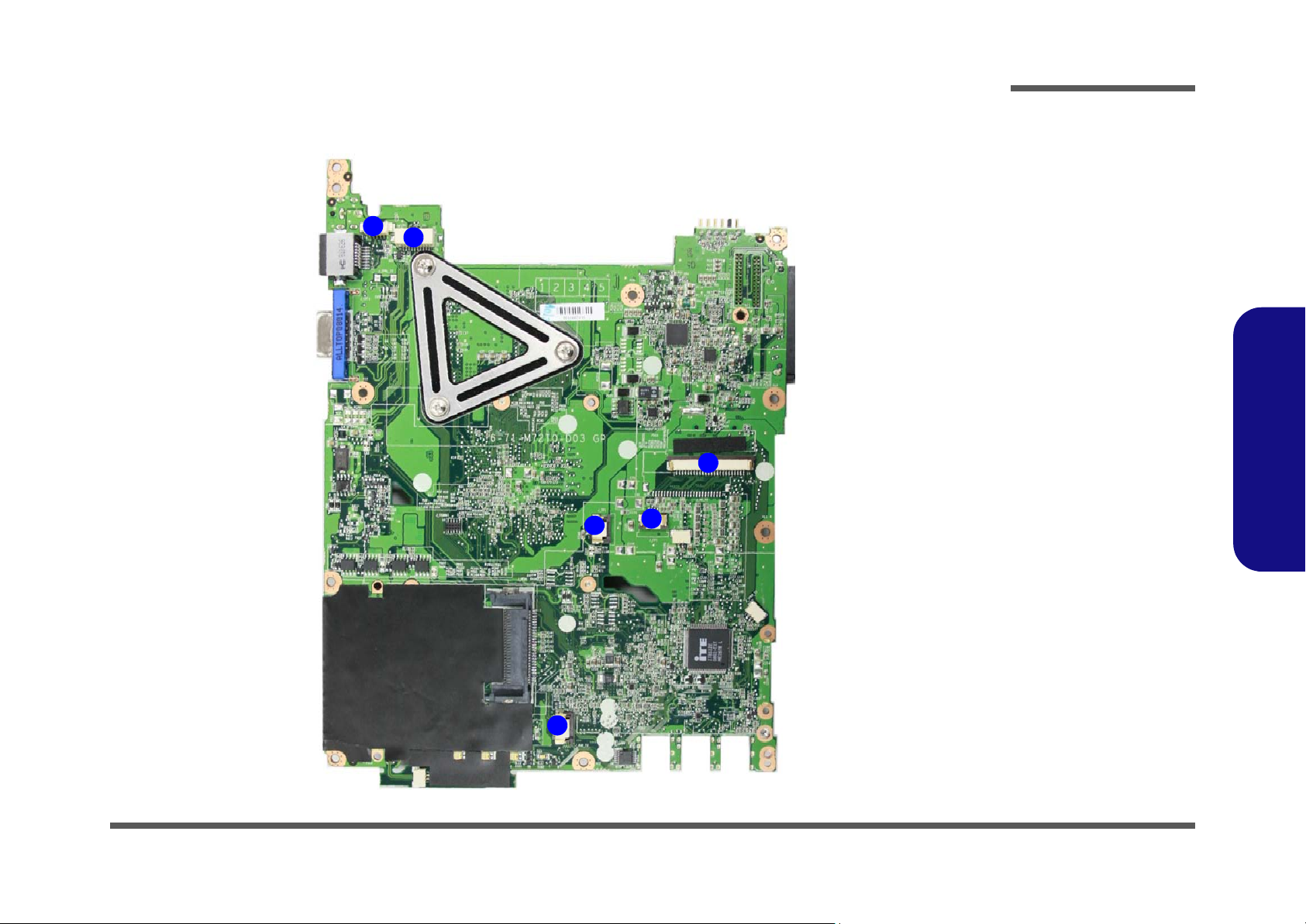
Mainboard Overview - Top (Connectors)
1
2
6
Figure 9
Mainboard Top
Connectors
1. Hot-key
Connector
2. LCD Cable
Connector
3. Keyboard Cable
Connector
4. Audio Board
Connector
5. Microphone
Cable Connector
6. TouchPad Cable
Connector
4
5
1.Introduction
3
Mainboard Overview - Top (Connectors) 1 - 11
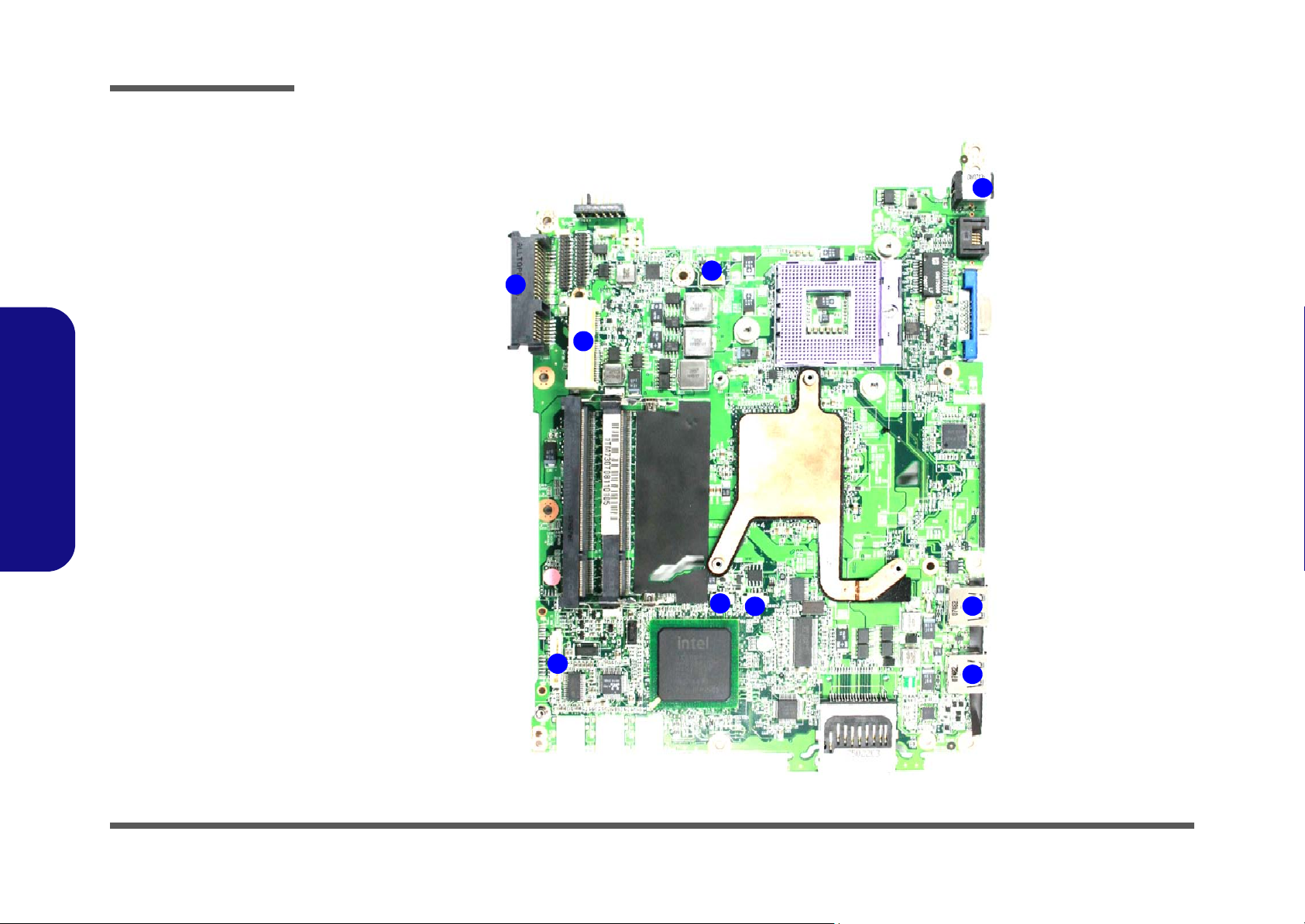
Introduction
Figure 10
Mainboard Bottom
Connectors
1. BT Cable
Connector
2. Multi Board
Connector
3. CD-ROM
Connector
4. HDD Connector
5. CMOS Bat.
Connector
6. CPU Fan Cable
Connector
7. DC-In Jack
8. USB Port
1.Introduction
Mainboard Overview - Bottom (Connectors)
7
1
4
2
1 - 12 Mainboard Overview - Bottom (Connectors)
5
6
3
8
8

Chapter 2: Disassembly
Overview
This chapter provides step-by-step instructions for disassembling the M730T/M735T series notebook’s parts and subsystems. When it comes to reassembly, reverse the procedures (unless otherwise indicated).
We suggest you completely review any procedure before you take the computer apart.
Disassembly
Procedures such as upgrading/replacing the RAM, optical device and hard disk are included in the User’s Manual but are
repeated here for your convenience.
To make the disassembly process easier each section may have a box in the page margin. Information contained under
the figure # will give a synopsis of the sequence of procedures involved in the disassembly procedure. A box with a
lists the relevant parts you will have after the disassembly process is complete. Note: The parts listed will be for the disassembly procedure listed ONLY, and not any previous disassembly step(s) required. Refer to the part list for the previous disassembly procedure. The amount of screws you should be left with will be listed here also.
A box with a will also provide any possible helpful information. A box with a contains warnings.
An example of these types of boxes are shown in the sidebar.
2.Disassembly
Information
Warning
Overview 2 - 1

Disassembly
2.Disassembly
NOTE: All disassembly procedures assume that the system is turned OFF, and disconnected from any power supply (the
battery is removed too).
Maintenance Tools
The following tools are recommended when working on the notebook PC:
• M3 Philips-head screwdriver
• M2.5 Philips-head screwdriver (magnetized)
• M2 Philips-head screwdriver
• Small flat-head screwdriver
• Pair of needle-nose pliers
• Anti-static wrist-strap
Connections
Connections within the computer are one of four types:
Locking collar sockets for ribbon connectors To release these connectors, use a small flat-head screwdriver to
gently pry the locking collar away from its base. When replacing the connection, make sure the connector is oriented in the
same way. The pin1 side is usually not indicated.
2 - 2 Overview
Pressure sockets for multi-wire connectors To release this connector type, grasp it at its head and gently
rock it from side to side as you pull it out. Do not pull on the
wires themselves. When replacing the connection, do not try to
force it. The socket only fits one way.
Pressure sockets for ribbon connectors To release these connectors, use a small pair of needle-nose pli-
ers to gently lift the connector away from its socket. When replacing the connection, make sure the connector is oriented in
the same way. The pin1 side is usually not indicated.
Board-to-board or multi-pin sockets To separate the boards, gently rock them from side to side as
you pull them apart. If the connection is very tight, use a small
flat-head screwdriver - use just enough force to start.

Maintenance Precautions
The following precautions are a reminder. To avoid personal injury or damage to the computer while performing a removal and/or replacement job, take the following precautions:
1. Don't drop it. Perform your repairs and/or upgrades on a stable surface. If the computer falls, the case and other
components could be damaged.
2. Don't overheat it. Note the proximity of any heating elements. Keep the computer out of direct sunlight.
3. Avoid interference. Note the proximity of any high capacity transformers, electric motors, and other strong mag-
netic fields. These can hinder proper performance and damage components and/or data. You should also monitor
the position of magnetized tools (i.e. screwdrivers).
4. Keep it dry. This is an electrical appliance. If water or any other liquid gets into it, the computer could be badly
damaged.
5. Be careful with power. Avoid accidental shocks, discharges or explosions.
•Before removing or servicing any part from the computer, turn the computer off and detach any power supplies.
•When you want to unplug the power cord or any cable/wire, be sure to disconnect it by the plug head. Do not pu ll on the wir e.
6. Peripherals – Turn off and detach any peripherals.
7. Beware of static discharge. ICs, such as the CPU and main support chips, are vulnerable to static electricity.
Before handling any part in the computer, discharge any static electricity inside the computer. When handling a
printed circuit board, do not use gloves or other materials which allow static electricity buildup. We suggest that
you use an anti-static wrist strap instead.
8. Beware of corrosion. As you perform your job, avoid touching any connector leads. Even the cleanest hands produce oils which can attract corrosive elements.
9. Keep your work environment clean. Tobacco smoke, dust or other air-born particulate matter is often attracted
to charged surfaces, reducing performance.
10. Keep track of the components. When removing or re placing any part, be careful not to leave small p arts, such as
screws, loose inside the computer.
Disassembly
Power Safety
Warning
Before you undertake
any upgrade procedures, make sure that
you have turned off the
power, and disconnected all peripherals
and cables (including
telephone lines). It is
advisable to also remove your battery in
order to prevent accidentally turning the
machine on.
2.Disassembly
Cleaning
Do not apply cleaner directly to the computer, use a soft clean cloth.
Do not use volatile (petroleum distillates) or abrasive cleaners on any part of the computer.
Overview 2 - 3

Disassembly
Disassembly Steps
The following table lists the disassembly steps, and on which page to find the related information. PLEASE PERFORM
THE DISASSEMBLY STEPS IN THE ORDER INDICATED.
2.Disassembly
To remove the Battery:
1. Remove the battery page 2 - 5
To remove the HDD:
1. Remove the battery page 2 - 5
2. Remove the HDD page 2 - 6
To remove the Optical Device:
1. Remove the battery page 2 - 5
2. Remove the Optical device page 2 - 8
To remove the System Memory:
1. Remove the battery page 2 - 5
2. Remove the system memory page 2 - 9
To remove the Inverter Board:
1. Remove the battery page 2 - 5
2. Remove the inverter board page 2 - 11
To remove and install a Processor:
To remove the Wireless LAN Module:
1. Remove the battery page 2 - 5
2. Remove the wireless LAN page 2 - 14
To remove the Bluetooth Module:
1. Remove the battery page 2 - 5
2. Remove the Bluetooth page 2 - 15
To remove the Keyboard:
1. Remove the battery page 2 - 5
2. Remove the keyboard page 2 - 16
To remove the Modem:
1. Remove the battery page 2 - 5
2. Remove the HDD page 2 - 6
3. Remove the system memory page 2 - 9
4. Remove the Optical device page 2 - 8
5. Remove the processor page 2 - 12
6. Remove the keyboard page 2 - 16
7. Remove the modem page 2 - 17
1. Remove the battery page 2 - 5
2. Remove the processor page 2 - 12
2 - 4 Disassembly Steps
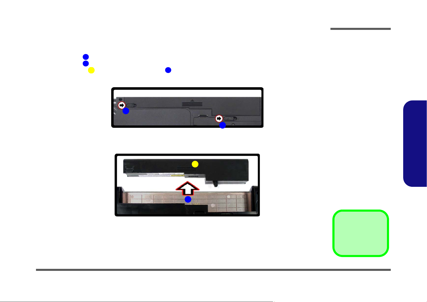
Removing the Battery
Disassembly
1. Turn the computer off, and turn it over.
2. Slide the latch in the direction of the arrow.
3. Slide the latch in the direction of the arrow, and hold it in place.
4. Slide the battery in the direction of the arrow .
1
2
3
6
a.
2
b.
4
3
Figure 1
Battery Removal
a. Slide the latch and hold
in place.
b. Slide the battery in the di-
rection of the arrow.
2.Disassembly
1
4
3. Battery
Removing the Battery 2 - 5
Disassembly
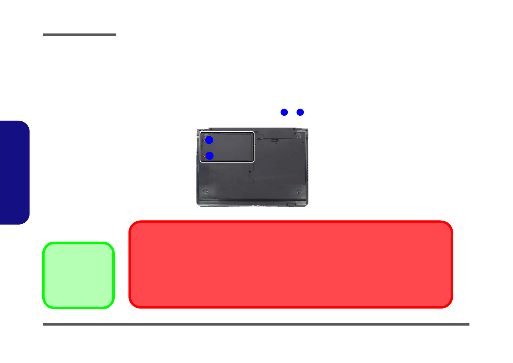
Removing the Hard Disk Drive
Figure 2
HDD Assembly
Removal
a. Locate the HDD bay
cover and loosen the
screw(s).
2.Disassembly
The hard disk drive can be taken out to accommodate other 2.5" serial (SATA) hard disk drives with a height of 9.5mm
(h). Follow your operating system’s installation instructions, and install all necessary drivers and utilities (as outlined in
Chapter 4 of the User’s Manual) when setting up a new hard disk.
Hard Disk Upgrade Process
1. Turn off the computer, and remove the battery (page 2 - 5).
2. Locate the hard disk bay cover and loosen screws & .
a.
1
1 2
Note:
2
Only one model is pictured
here, however the component locations are the same
for both models.
HDD System Warning
•2 Screws
New HDD’s are blank. Before you begin make sure:
You have backed up any data you want to keep from your old HDD.
You have all the CD-ROMs and FDDs required to install your operating system and programs.
If you have access to the internet, download the latest application and hardware driver updates for the operating system you plan
to install. Copy these to a removable medium.
2 - 6 Removing the Hard Disk Drive
 Loading...