

CLA-VAL eFlowMeter X144D-AF, X144D e-FlowMeter Quick Start Installation & Removal Instructions
Page 1

X144D-AF e-FlowMeter
CLA-VAL
Quick Start Installation & Removal Instructions
X144D-AF e-FlowMeter Included Hardware
1
2
1
flow
Sensing Probe
Flow
Display
Sensing
3
Cable
Complete
4
Installation Kit
Parts List
1) Sensing Probe
2) Flow Display
3) Sensing Cable
a) Insertion Tool
4) Installation Kit containing:
a) Insertion Tool
b) Locking Collar with
(a and b come assembled)
Score
Marks
b)
Thumb Set
Screw
Step-By-Step X144D-AF e-FlowMeter Installation Instructions
Isolation Valves
Step 1: Take necessary safety precautions
• Isolate the control valve using main line
isolation valves
• Bleed pressure from valve before removing
body plug
• Remove an inlet body plug
NOTE: If both inlet body tappings are used for
the pilot system, consult factory for correct
modification instructions.
Thumb Set Screw
Locking
Collar
2
Step 2A:
Loosen Knurled Lock Nut on e-FlowMeter Assembly
3
Step 3A: Screw Locking Collar on straight threads. Insert
angled end of provided tool as shown, until it stops
Thumb Set Screw
Locking Collar
tape not supplied
4
Sensor/Head Assembly
sensor
tip
Threaded Swivel Insert
Step 2B: Pull apart. Straighten Measurement Cylinder by
hand. Set aside Sensor/Head in safe location,
protecting sensor tip
Thumb Set Screw
Step 3B: Tighten Thumb Set Screw
Step 4: Apply Teflon® tape to NPT Threads
• Check threads on valve
• Use thread chasing tool (not supplied), if
necessary
Measurement
Cylinder
Page 2

X144 e-FlowMeter
Quick Start Installation & Removal Instructions
Step-By-Step X144D-AF e-FlowMeter Installation Instructions (continued)
flow
inside view
top view
Step 5: Insert straightened Swivel Insert/Measurement
Cylinder Assembly into valve, orient arrow on
wrench flat to point downstream
7
65
Verify score mark is
flush with flat face
of straight thread
to ensure full
engagement
Step 6: Loosen Thumb Set Screw. Remove Locking Collar
from tool. Remove tool and re-insert opposite end into
Swivel Assembly. Engage the tool and push firmly to orient
Measurement Cylinder 90˚ into flow path
8
Step 7: Remove tool from Threaded Swivel Insert
9
Step 9: Line-Up Centering Groove on straight threads
with Centering Pin; push to seat o-ring
Centering
Pin
Centering
Groove
Step 8: Insert tip of e-FlowMeter Sensor/Head Assembly
into Threaded Swivel Insert
10
Knurled
Lock
Please see display
programming manual for
display configuration.
Step 10: HAND TIGHTEN Knurled Lock onto straight
threads. Attach Sensing Cable to Sensing Probe
and Flow Display.
Proceed in accordance with Wiring Diagram
Page 3
X144D-AF e-FlowMeter
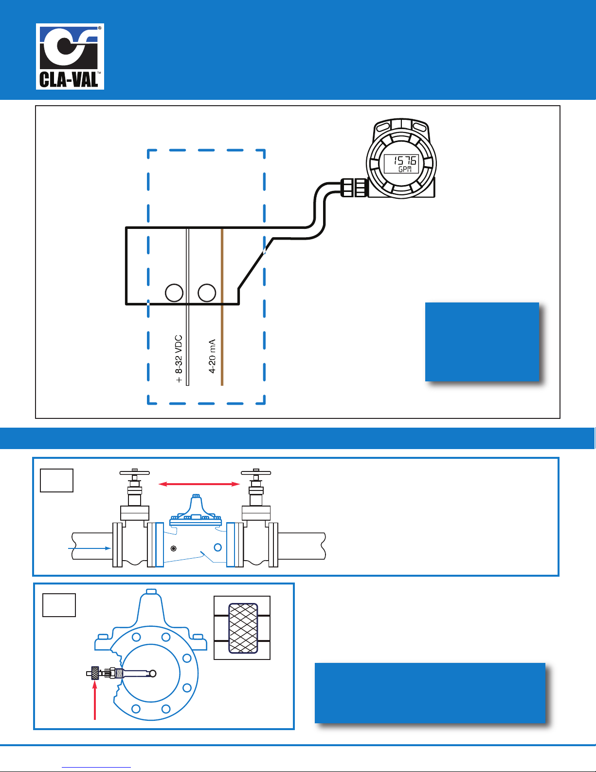
X144D-AF
Flow Display
7
8
4-20mA Loop
Power
Circuit Wiring
CLA-VAL
flow
Quick Start Installation & Removal Instructions
Standard Wiring
for additional
wiring diagrams,
download N-144
IOM Manual at
www.cla-val.com
Step-By-Step X144D-AF e-FlowMeter Removal Instructions
1
2
Isolation Valves
Knurled
Lock
Step 1: Take necessary safety precautions
a) Isolate the control valve
using main line isolation valves
b) Bleed pressure from valve before
removing the e-FlowMeter
c) Disconnect power to all electronic
devices on valve, including e-FlowMeter
Step 2: After isolating the valve, bleeding pressure and
disconnecting electronic devices, hand loosen the
Knurled Lock from straight threads
call 800.942.6326 for assistance
or log-on to
www.cla-val.com for more information
Page 4

X144D-AF e-FlowMeter
Quick Start Installation & Removal Instructions
Step-By-Step X144D-AF e-FlowMeter Removal Instructions (continued)
3
Step 3:
• Remove the e-FlowMeter Sensor/Head Assembly by
pulling straight outward, being careful not to hit the
sensor tip on the Threaded Swivel Insert tube
• Set Sensor/Head Assembly aside, taking care to
protect the sensor tip
5
flow
Before
flow
After
4
Step 4:
• Orient the Installation Tool so that the bevel is
facing downstream, away from the centering
groove as shown in detail drawing, and insert into
the Threaded Swivel Insert
6
entering groove
c
top view
Step 5:
• Once inserted into the Threaded Swivel Insert tube,
the Installation Tool will engage the top face of the
Measurement Cylinder and force it to the 45° position,
as shown above
top view
7
Step 7:
• Once engaged, use light force to straighten the
measurement cylinder, and then secure the Installation
Tool in place with Locking Collar in locked position
N-X144D-AF Quick Start, Removal & Wiring (R-07-2017)
Installation Tool lip
Step 6:
• Slide Installation Tool straight out, then rotate 180° so that
the bevel is facing upstream of the valve, which is now
facing the same direction of the centering groove, see above
• The lip of the Installation Tool will engage the inside of the
Measurement Cylinder as shown in photo
8
Step 8:
• Remove Threaded Swivel Insert from the valve tapping with
the Measurement Cylinder straightened
• Insert body plug into tapping while servicing the e-FlowMeter
 Loading...