

Page 1

60-31/660-31
Page 2

0
LO
......
......
I
I
O'I
N
N
......
I
I
......
......
0
0
~
a_
<
0::
IO
"
co
v
N
0
(.)
,....,.
~
N
~
co
N
0::
<
0
_J
(.)
(.)
w
0::
'-'
0
a_
LL
w
<
z
0::
(.)
~
0::
<
~
w
LL
Ul
_J
_J
<
0
z
CD
0
~
F
a_
Ul
0
Cl
0
~
w
0
0
:::!!
0
w
<
0::
z
a_
5
I=!
I
v
<
N
0
I
"
>-
~
CD
<
>-
:::l
<
:::::>
:e
:::I!
LL.I
(/]
5'
LL.I
a::
I-
0
:z:
0
0
I
is
~
i!5
!i:
~
co
a::
~
......
i5
0
ti5
(.)
5'
w
LL.I I..._..
a::
0
w
Ul
cs
_J
w
Li:
0::
w
z
Ul
0
0
Vi
0
5
ID
w
0
0::
w
w
0
w
0
Ul
<
CVCL
1 @ 3 4
DIST
CODE
002
SHEET
1
DRAWING
NO.
91325
BOOSTER PUMP CONTROL VALVE
WITH
HY-CHECK
(4"
AND LARGER ONLY)
DESIGN
DRAWN
CHK'D
APV'D
- - - -
NOT
FURNISHED
BY
CLA-VAL
CO.
~~~3
- - - - -
OPTIONAL
FEAlURES
~
I
/I\
2
~E6
N.C. r
~
COM.
N.O.
~7A
4
/6
/
~
(
------00--------
(
'\7..,
L_
+--
\.
I
P3_/
-/
f-j /
MGR
KD
CH
-------
n
~
n.
-·~~
INLET
~
~
OUTLET
B
........
•USE
CV
FLOW
CONTROLS
ON
6" & SMALLERlQ(60-3}
1
*USE
CV
FLOW
CONTROLS
ON
8" & SMALLER
VALVES
(660-31)
1
1:1
BASIC
COMPONENTS
QTY
L
1
100-04
HY-CHECK
(60-31)
MAIN
VALVE
1
100-23
HY-CHECK
(660-31)
MAIN
VALVE
8 CK2
COCK
(ISOLATION VALVE)
2
102C-3H
3-WAY
HYTROL
W/PIPE
PLUG
3
CS3SM
SOLENOID
CONTROL
4 X10⁵LCW LIMIT
SWITCH
ASSEMBLY 1
5
CDC
CHECK
VALVE 1
6 CDC/CSC
CHECK
VALVE 1
7 *CV
FLOW
CONTROL/CNA
NEEDLE
VALVE 2
OPTIONAL
FEATURE
SUFFIX
ADDED
TO
CATALOG
NUMBER
A X46A
FLOW
CLEAN
STRAINER
1
B CK2
COCK
(ISOLATION VALVE) 3
P
X141
PRESSURE
GAUGE
ASSEMBLY 3
Y X43
"y"
STRAINER
1
OF
4
IREV
p
4-4-80
5-5-80
5-19-80
--7B
"lllS
DRAWING
IS
11£
PRa'ERlY
Cl'
a..A-VAl
CO.
AND
SAME
AND
COPIES
MADE
lHERECI',
IF
ANY,
SHAl.l
BE
REMNED
TO
IT~
DEMAND.
DELMRY
AND
DISQ.OSURE
HERE<I'
ARE
MADE
sa.n.Y ~ C<NllllOO
lHAT
lHE
SAME
SHAl.l
NOT
BE
USED,
COPIED
OR
REPROOUCED,
NOR
SHAl.l
lHE
SUB.ECT
HERE<I'
BE
DISQ.OSED
IN
ANY
MANNER
TO
ANYl*E
FOR
ANY
PURPOSE,
EXCEPT
AS
HEREIN
AUlHORIZED,
WllHOUT
PRIOR
WlllTTEN
APPROVAl
Cl'
a.A-VAL
CO.
lHIS
DRAWNG
IS
SUBllTIED
CMIDENllAl.lY
AND
llAY
NOT
BE
USED
IN
lHE
llANUFACME
Cl'
ANY
llA1ERIAL
OR
PROOIJCT
OlHER
lHAN
SUQl
llA1ERIAl.S
AND
PRODUClS
FURNISHED
TO
a..A-VAl
CO.
WllE11£R
OR
NOT
lHE
EQUIPMENT
OR
INFORllAllOO
SHO\ltl
HEREOO
IS
PAlENTED
OR
OlHERWISE
PROlECTED
FUil
1Tn.E
AND
C<l'YRIGilS.
IF
AN't'.
IN
AND
TO
lHIS
DRAWING
AND/OR
INFORllAllOO
DEU\fRED
OR
SUBlllTIED
ARE
FULlY
RESER\fll
BY
a..A-VAl
CO.'
Page 3
>-
CD
1-
w
w
I
Ul
w
w
Ul
CVCL
1 @ 3 4
DIST
CODE
002
SHEET
2
OF
4
DRAWING
NO.
IREV
p
91325
DESIGN
BOOSTER
PUMP
CONTROL
VALVE
WITH
HY-CHECK
(4"
AND
LARGER
ONLY)
DRAWN
MGR
4-4-80
CHK'D
KD
5-5-80
APV'D
CH
5-19-80
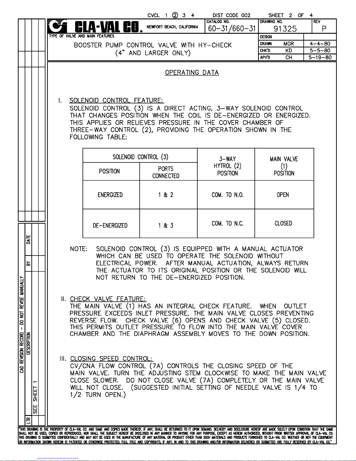
OPERATING
DATA
I.
SOLENOID
CONTROL
FEATURE:
SOLENOID
CONTROL
(3)
IS A DIRECT
ACTING,
3-WAY
SOLENOID
CONTROL
THAT
CHANGES
POSITION
WHEN
THE
COIL
IS
DE-ENERGIZED
OR
ENERGIZED.
THIS
APPLIES
OR
RELIEVES
PRESSURE
IN
THE
COVER
CHAMBER
OF
THREE-WAY
CONTROL
(2),
PROVIDING
THE
OPERATION
SHOWN
IN
THE
FOLLOWING
TABLE:
SOLENOID
CONTROL
(3)
POSITION
ENERGIZED
DE-ENERGIZED
PORTS
CONNECTED
1 & 2
1
& 3
3-WAY
HYTROL
(2)
POSITION
COM.
TO
N.O.
COM.
TO
N.C.
MAIN
VALVE
(1)
POSITION
OPEN
CLOSED
NOTE:
SOLENOID
CONTROL
(3)
IS
EQUIPPED
WITH
A MANUAL
ACTUATOR
WHICH
CAN
BE
USED
TO
OPERATE
THE
SOLENOID
WITHOUT
ELECTRICAL
POWER.
AFTER
MANUAL
ACTUATION,
ALWAYS
RETURN
THE
ACTUATOR
TO
ITS
ORIGINAL
POSITION
OR
THE
SOLENOID
WILL
NOT
RETURN
TO
THE
DE-ENERGIZED
POSITION.
II.
CHECK
VALVE
FEATURE:
THE
MAIN
VALVE
(1)
HAS
AN
INTEGRAL
CHECK
FEATURE.
WHEN
OUTLET
PRESSURE
EXCEEDS
INLET
PRESSURE,
THE
MAIN
VALVE
CLOSES
PREVENTING
REVERSE
FLOW.
CHECK
VALVE
(6)
OPENS
AND
CHECK
VALVE
(5)
CLOSED.
THIS
PERMITS
OUTLET
PRESSURE
TO
FLOW
INTO
THE
MAIN
VALVE
COVER
CHAMBER
AND
THE
DIAPHRAGM
ASSEMBLY
MOVES
TO
THE
DOWN
POSITION.
Ill.
CLOSING
SPEED
CONTROL:
CV
/CNA
FLOW
CONTROL
(7
A)
CONTROLS
THE
CLOSING
SPEED
OF
THE
MAIN
VALVE.
TURN
THE
ADJUSTING
STEM
CLOCKWISE
TO
MAKE
THE
MAIN
VALVE
CLOSE
SLOWER.
DO
NOT
CLOSE
VALVE
(7A)
COMPLETELY
OR
THE
MAIN
VALVE
WILL
NOT
CLOSE.
(SUGGESTED
INITIAL
SETTING
OF
NEEDLE
VALVE
IS
1/4
TO
1
/2
TURN
OPEN.)
"lllS
DRAWING
IS
11£
PRa'ERlY
Cl'
a..A-VAl
CO.
AND
SAME
AND
COPIES
MADE
lHERECI',
IF
ANY,
SHAl.l
BE
REMNED
TO
IT~
DEMAND.
DELMRY
AND
DISQ.OSURE
HERE<I'
ARE
MADE
sa.n.Y ~ C<NllllOO
lHAT
lHE
SAME
SHAl.l
NOT
BE
USED,
COPIED
OR
REPROOUCED,
NOR
SHAl.l
lHE
SUB.ECT
HERE<I'
BE
DISQ.OSED
IN
ANY
MANNER
TO
ANYl*E
FOR
ANY
PURPOSE,
EXCEPT
AS
HEREIN
AUlHORIZED,
WllHOUT
PRIOR
WlllTTEN
APPROVAl
Cl'
a.A-VAL
CO.
lHIS
DRAWNG
IS
SUBllTIED
CXN'IDENllAl.lY
AND
llAY
NOT
BE
USED
IN
lHE
llANUFACME
Cl'
ANY
llAlERIAl
OR
PROOIJCT
OlHER
lHAN
SUQl
llAlERIAl.S
AND
PRODIJClS
FURNISHED
TO
a..A-VAl
CO.
WllE11£R
OR
NOT
lHE
EQUIPMENT
OR
INFORllAllOO
SHO\ltl
HEREOO
IS
PAlENTED
OR
OlHERWISE
PROlECTED
FUil
1Tn.E
AND
C<l'YRIGilS.
IF
AN't'.
IN
AND
TO
lHIS
DRAWING
AND/OR
INFORllAllOO
DEU\fRED
OR
SUBlllTIED
ARE
FULlY
RESER\fll
BY
a..A-VAl
CO.'
Page 4

CVCL
1 @ 3 4
DIST
CODE
002
BOOSTER
PUMP
CONTROL
VALVE
WITH
HY-CHECK
(4"
AND
LARGER
ONLY)
OPERATING
DATA-CONTINUED
IV.
OPENING
SPEED
CONTROL:
SHEET
3
DRAWING
NO.
91325
DESIGN
DRAWN
MGR
CHK'D
KD
APV'D
CH
CV
/CNA
FLOW
CONTROL
(7B)
CONTROLS
THE
OPENING
SPEED
OF
THE
OF
4
IREV
p
4-4-80
5-5-80
5-19-80
MAIN
VALVE
TURN
THE
ADJUSTING
STEM
CLOCKWISE
TO
MAKE
THE
MAIN
VALVE
OPEN
SLOWER.
DO
NOT
CLOSE
VALVE
(7B)
COMPLETELY
OR
THE
MAIN
VALVE
WILL
NOT
OPEN.
(SUGGESTED
INITIAL
SETTING
OF
NEEDLE
VALVE
IS 1 /4
TO
1
/2
TURN
OPEN).
V.
SWITCH
ASSEMBLY
FEATURE:
SWITCH
ASSEMBLY
(4)
IS
ACTUATED
BY A STEM
EXTENSION
ATTACHED
TO
THE
MAIN
VALVE
STEM.
THE
SWITCH
ASSEMBLY
IS
FACTORY
ADJUSTED
TO
ACTUATE
A SINGLE-POLE DOUBLE-THROW
SWITCH
WHEN
THE
MAIN
VALVE
IS
ALMOST
CLOSED.
WHEN
THE
MAIN
VALVE
STARTS
TO
OPEN,
THE
SPRING
LOADED
SWITCH
ACTUATING
LEVER
IS
RELEASED
AND
RETURNS
THE
SWITCH
TO
ITS
NORMAL
POSITION.
VI.
OPTIONAL
FEATURE
OPERATING
DATA:
I=!
SUFFIX A (FLOW
CLEAN
STRAINER):
~
A SELF-CLEANING
STRAINER
IS
INSTALLED
IN
THE
MAIN
VALVE
INLET
BODY
BOSS
WHICH
PROTECTS
THE
PILOT
SYSTEM
FROM
FOREIGN
PARTICLES.
>-
CD
1-
w
w
I
Ul
w
w
Ul
SUFFIX B (ISOLATION
VALVES):
CK2
COCKS
(B)
ARE
USED
TO
ISOLATE
THE
PILOT
SYSTEM
FROM
MAIN
LINE
PRESSURE.
THESE
VALVES
MUST
BE
OPEN
DURING
NORMAL
OPERATION.
SUFFIX P (PRESSURE
GAUGE):
PRESSURE
GAUGES
(P1
), (P2),
AND
(P3)
PROVIDE
PRESSURE
READING
IN
THE
INLET,
OUTLET,
AND
COVER
CONNECTIONS.
SUFFIX
y CY-STRAINER):
A Y-PATTERN
STRAINER
IS
INSTALLED
IN
THE
PILOT
SUPPLY
LINE
TO
PROTECT
THE
PILOT
SYSTEM
FROM
FOREIGN
PARTICLES.
THE
STRAINER
SCREEN
MUST
BE
CLEANED
PERIODICALLY.
"lllS
DRAWING
IS
11£
PRa'ERlY
Cl'
CLA-VAl
CO.
AND
SAME
AND
COPIES
MADE
lHERECI',
IF
ANY,
SHAl.l
BE
REMNED
TO
IT~
DEMAND.
DELMRY
AND
DISQ.OSURE
HERE<I'
ARE
MADE
sa.n.Y ~ COOTION
lHAT
lHE
SAME
SHAl.l
NOT
BE
USED,
COPIED
OR
REPROOUCED,
NOR
SHAl.l
lHE
SUB.ECT
HERE<I'
BE
DISQ.OSED
IN
ANY
MANNER
TO
ANYl*E
FOR
ANY
PURPOSE,
EXCEPT
AS
HEREIN
AUlHORIZED,
WllHOUT
PRIOR
WlllTTEN
APPROVAl
Cl'
a.A-VAL
CO.
lHIS
DRAWNG
IS
SUBllTIED
CMIDENllAl.lY
AND
llAY
NOT
BE
USED
IN
lHE
llANUFACME
Cl'
ANY
llAlERIAl
OR
PROOIJCT
OlHER
lHAN
SUQl
llAlERIAl.S
AND
PRODUClS
FURNISHED
TO
CLA-VAl
CO.
WllE11£R
OR
NOT
lHE
EQUIPMENT
OR
INFORMATION
SHO\ltl
HEREON
IS
PAlENTED
OR
011£RWISE
PROlECTED
FUil
1Tn.E
AND
C<l'YRIGilS.
IF
AN't'.
IN
AND
TO
lHIS
DRAWING
AND/OR
INFORMATION
DEU\fRED
OR
SUBlllTIED
ARE
FULlY
RESER\fll
BY
CLA-VAl
CO.'
Page 5

>-
CD
1-
w
w
I
Ul
w
w
Ul
CVCL
1 @ 3 4
DIST
CODE
002
BOOSTER
PUMP
CONTROL
VALVE
WITH
HY-CHECK
(4"
AND
LARGER
ONLY)
OPERATING
DATA-CONTINUED
VII.
CHECK
LIST
FOR
PROPER
OPERATION:
( )
SYSTEM
VALVES
OPEN
UPSTREAM
AND
DOWNSTREAM.
SHEET
4
OF
4
DRAWING
NO.
IREV
p
91325
DESIGN
DRAWN
MGR
4-4-80
CHK'D
KD
5-5-80
APV'D
CH
5-19-80
( )
AIR
REMOVED
FROM
THE
MAIN
VALVE
COVER
AND
PILOT
SYSTEM
AT
ALL
HIGH
POINTS.
( )
PERIODIC
CLEANING
OF
STRAINER
(Y)
IS
RECOMMENDED
(OPTIONAL
FEATURE).
( )
CV
FLOW
CONTROLS
(7
A)
AND
(7B)
OPEN
AT
LEAST 4 TURNS
(OPTIONAL
FEATURE).
( )
NEEDLE
VALVES
(7A)
AND
(7B)
OPEN
AT
LEAST
1/4
TURN.
( )
CORRECT
VOLTAGE
TO
SOLENOID
CONTROL
(3).
( ) MANUAL
OPERATOR
OF
SOLENOID
CONTROL
(3)
DISENGAGED.
( )
LIMIT
SWITCH
ASSEMBLY
(4)
PROPERLY
WIRED.
( )
CK2
COCK
(8)
OPEN
DURING
NORMAL
OPERATION.
( )
CK2
COCKS
(B)
OPEN
(OPTIONAL
FEATURE).
"lllS
DRAWING
IS
11£
PRa'ERlY
Cl'
a..A-VAl
CO.
AND
SAME
AND
COPIES
MADE
lHERECI',
IF
ANY,
SHAl.l
BE
REMNED
TO
IT~
DEMAND.
DELMRY
AND
DISQ.OSURE
HERE<I'
ARE
MADE
sa.n.Y ~ C<NllllOO
lHAT
lHE
SAME
SHAl.l
NOT
BE
USED,
COPIED
OR
REPROOUCED,
NOR
SHAl.l
lHE
SUB.ECT
HERE<I'
BE
DISQ.OSED
IN
ANY
MANNER
TO
ANYl*E
FOR
ANY
PURPOSE,
EXCEPT
AS
HEREIN
AUlHORIZED,
WllHOUT
PRIOR
WlllTTEN
APPROVAl
Cl'
a.A-VAL
CO.
lHIS
DRAWNG
IS
SUBllTIED
CXN'IDENllAl.lY
AND
llAY
NOT
BE
USED
IN
lHE
llANUFACME
Cl'
ANY
llAlERIAl
OR
PROOIJCT
OlHER
lHAN
SUQl
llAlERIAl.S
AND
PRODIJClS
FURNISHED
TO
a..A-VAl
CO.
WllE11£R
OR
NOT
lHE
EQUIPMENT
OR
INFORllAllOO
SHO\ltl
HEREOO
IS
PAlENTED
OR
OlHERWISE
PROlECTED
FUil
1Tn.E
AND
C<l'YRIGilS.
IF
AN't'.
IN
AND
TO
lHIS
DRAWING
AND/OR
INFORllAllOO
DEU\fRED
OR
SUBlllTIED
ARE
FULlY
RESER\fll
BY
a..A-VAl
CO.'
Page 6

• Built-in Automatic Check Valve
• Drip Tight, Positive Seating
• Globe or Angle Pattern
• Service Without Removal From Line
• Every valve factory-tested
The C la- Val M ode l 100 -04 Hy-C hec k Val ve is a
hydraulically operated diaphragm valve with a built-in check
feature to prevent return flow. Available in globe or angle
pa ttern, it con si st s of a body, co ve r and diaphragm
assembly. The diaphragm assembly which is guided top
and botto m by a precisi on machined stem is the only
moving part.
A synthetic rubber disc retained on three and one half sides
forms a drip-tight seal wi th the renewable seat when
operating pressure is applied a bove the no n-wicking
di aphragm . W hen pressu re above th e d iaphragm i s
relieved, the valve opens wide. The rate of closing or
opening can be controlled by modulating the flow into or out
of the cover chamber. When a pressure reversal occurs the
split stem will immediately allow the disc retainer assembly
to check cl osed reg ar dless of the posi ti on of t he
diaphragm.
The Model 100-04 is used on system applications such as
remote control, pressure regulation, solenoid control, etc.;
wherever a positive check feature is necessary to prevent
reverse flow. Its packless construction and simplicity of
desig n mini miz es mai ntena nce an d as su res a long
dependable service life.
100-04
Hy-Check Valve
Full Open Operation
When pre ssure in th e cov er
chamber is relieved to a zone of
lower pressure, the line pressure at
th e valve inl et opens the v alve,
allowing full flow.
Check Action
When a static condition or pressure
reversal occurs, the split stem design
allows the valve to instantly check
closed. Re turn flo w is preven te d
regar dle ss of
the d ia phr agm's
position.
Tight Closing Operation
When pressure from the valve inlet
is applied to the cover chamber, the
valve closes drip-tight.
On-Off Control
On-Off Control
Modulating
Control
Principle of Operation
Note: For optimum operation of built-in check feature, installation with stem vertically up is recommended.
MODEL
see page 2 for
approvals
Page 7

Epoxy Coating - suffix KC
This opti on N SF 6 1 Li st ed and F DA
approved, fusion bonded epoxy coating is
for use with cast iron, ductile iron or steel
valves. This coating is resistant to various
water conditions, certain acids, chemicals,
solvents and alkalies.
Epoxy coatings are
applied in accordance with AWWA coating
specifications C116-03.
Do not use with temperatures above
175° F
/80
°C.
Viton
®
Rubber Parts- suffix KB
Op tional diaphrag m, disc and o-ring
fabricated with Viton®synthetic rubber. Viton
®
is well suited for use with mineral acids, salt
solutions, chlorinated hydrocarbons, and
petroleum oils; and is primarily used in high
temperature applications up to 250°F/120°C.
Do not use with epoxy co ating ab ov e
175°F/80° C.
For assistance in selecting appropriate
valve options or valves manufactured
with spe cial des ign requ ire ments ,
pleas e co nta ct o ur R egion al S ale s
Office or Factory.
Options
S
pecifications
M
odel 100-04
O
perating Temp. Range
Available Sizes
Pattern Flanged
Globe
2" - 16"
50 - 400 mm
Angle
3" - 16"
80 - 400 mm
Fluids
-40° to 180° F
-40° to 82° C
Component Standard Material Combinations
Body & Cover Ductile Iron Cast Steel Bronze
Available Sizes (inches) 2" - 16" 2" - 16" 2" - 16"
Available Sizes (mm) 50 - 400 mm 50 - 400 mm 50 - 400 mm
Disc Retainer &
Diaphragm Washer
Cast Iron Cast Steel Bronze
Trim: Disc Guide,
Seat & Cover Bearing
Bronze is Standard
Stainless Steel is optional
Disc Buna-N®Rubber
Diaphragm Nylon Reinforced Buna-N®Rubber
Stem, Nut & Spring Stainless Steel
For material options not listed, consult factory.
Cla-Val manufactures valves in more than 50 different alloys.
Materials
B
OLT/HEX NUT (TYP)
C
OVER BEARING
UPPER DIAPHRAGM WASHER
S
EAT
STUD/BOLT (TYP)
BODY
INLET
PIPE PLUG (TYP)
OUTLET
SEAT-O-RING
DISC GUIDE
DIAPHRAGM
UPPER STEM NUT
COVER
PIPE PLUG (TYP)
UPPER STEM
DISC GUIDE SCREW (TYP)
L
OCK WASHER
LOWER STEM NUT
SPRING
LOWER STEM
S
PRING
LOWER DIAPHRAGM WASHER
DISC
DISC RETAINER
Valve Body & Cover
Pressure Class
Flanged Threaded
Grade Material
ANSI
Standards*
150
Class
300
Class
End‡
Details
ASTM A536 Ductile Iron B16.42 250 400 400
ASTM A216-WCB Cast Steel B16.5 285 400 400
UNS 87850 Bronze B16.24 225 400 400
Note: * ANSI standards are for flange dimensions only.
Flanged valves are available faced but not drilled.
‡ End Details machined to ANSI B2.1 specifications.
Valves for higher pressure are available; consult factory for details
Pressure Ratings
(Recommended Maximum Pressure - psi)
NSF International
recognizes Cla-Val
as complying with
NSF/ANSI 61 and all
applicable
requirements.
NSF/ANSI 372:
National Lead Free
Mandate “Reduction
of Lead in Drinking
Water Act”
Approvals
Page 8

V
alve Size
Inches 2 3 4 6 8 10 12 14 16
m
m.
50 80 100 150 200 250 300 350 400
C
V
Factor
Globe
Pattern
Gal./Min. (gpm.)
54 115 200 440 770 1245 1725 2300 3130
L
itres/Sec. (l/s.)
13 27.6 48 105.6 184.8 299 414 552 706
Angle
P
attern
G
al./Min. (gpm.)
61 139 240 541 990 1575 2500* 3060* 4200*
Litres/Sec. (l/s.)
14.6 33.4 58 130 238 378 600 734.4 1008
Equivalent
Length
of
Pipe
G
lobe
P
attern
F
eet (ft.)
51 85 116 211 291 347 467 422 503
M
eters (m.)
15.5 25.9 35.3 64.2 88.6 105.8 142.4 128.6 153.6
A
ngle
Pattern
Feet (ft.)
40 58 80 139 176 217 222* 238* 247*
M
eters (m.)
12.1 17.8 24.5 42.5 53.6 66.1 67.8 72.7 75.2
K
Factor
Globe Pattern
5.6 6.0 5.9 6.2 6.1 5.8 6.1 5.0 4.6
Angle Pattern
4.4 4.1 4.1 4.1 3.7 3.6 2.9 2.8 2.6
Liquid Displaced from
C
over Chamber When
V
alve Opens
F
l. Oz
— — — — — — — — —
U.S. Gal.
0.3 .08 .17 .53 1.26 2.51 4.0 6.5 9.6
m
l
121 303 643 — — — — — —
Litres
— — — 2.0 4.8 9.5 15.1 24.6 36.2
10 20 30 40 60 80 100 200 500 1000 2000 5000 10,000 20,000 50,000
1
2
3
4
6
8
10
20
30
40
60
80
100
53
Angle Valve Sizes (Inches)
Globe Valve Sizes (Inches)
4
6
810
12
12
46810
14
16
16
Pr
essure Drop — psi
14
Flow Rate gpm (water)
3
3
2
2
Model 100-04 Flow Chart (Based on normal flow through a wide open valve)
K =
894d
4
C
2
v
L =
K
12 f
K Factor (Resistance Coefficient)
The Value of K is calculated from the formula:
(U.S. system units)
Equivalent Length of Pipe
Equivalent lengths of pipe (L) are determined from the formula:
(U.S. system units)
Fluid Velocity
Fluid velocity can be calculated from the following formula:
(U.S. system units)
d
V =
.4085 Q
2
d
C
V
Factor
Formulas for computing C Factor, Flow (Q) and Pressure Drop
V
( P):
C
V
=
Q
P
C
V
=
Q
P
C
V
=
Q
P
2
V
Where:
U.S. (gpm) @ 1 psi differential at 60 F water
(l/s) @ 1 bar (14.5 PSIG) differential
or
at 15 C water
inside pipe diameter of Schedule 40 Steel Pipe (inches)
friction factor for clean, new Schedule 40 pipe
(dimensionless) (from Cameron Hydraulic Data,
18th Edition, P 3-119)
Resistance Coefficient (calculated)
Equivalent Length of Pipe (feet)
Flow Rate in U.S. (gpm) or (l/s)
Fluid Velocity (feet per second) or (meters per second)
Pressure Drop in (psi) or (bar)
=
=
=
=
=
=
=
=
=
P
V
Q
L
K
f
d
C
Functional Data
Model 100-04
*Estimated
Page 9

CLA-VAL
1701 Placentia Ave • Costa Mesa CA 92627 • Phone: 949-722-4800 • Fax: 949-548-5441 • E-mail: info@cla-val.com • www.cla-val.com
Copyright Cla-Val 2018
•
Printed in USA • Specifications subject to change without notice.
©
C
la-Val 100-04 Hy-Check Main Valve Dimensions
Service
Cla-Val Control Valves operate with maximum efficiency when mounted in horizontal piping with the main valve cover UP, however, other
positions are acceptable. Due to component size and weight of 8 inch and larger valves, installation with cover UP is advisable. We recommend
isolation valves be installed on inlet and outlet for maintenance. Adequate space above and around the valve for service personnel should be
considered essential. A regular maintenance program should be established based on the specific application data. However, we recommend a
thorough inspection be done at least once a year. Consult factory for specific recommendations.
E-100-04 (R-02/2018)
G
GG
D
Inlet
DD
F
100-04
Flanged
A
E
C
(MAX)
K
J
H
Inlet
Outlet
AA
B
(Diameter)
V
alve Size (Inches)
A 150 ANSI
AA 300 ANSI
B Diameter
C Maximum
D 150 ANSI
DD 300 ANSI
E
F 150 ANSI
FF 300 ANSI
G 150 ANSI
GG 300 ANSI
H NPT Body Tapping
J NPT Cover Center Plug
K NPT Cover Tapping
Stem Travel
Approx. Ship Weight (lbs)
15.00
1
5.62
11. 50
10.62
7.50
7.81
3.19
4.50
5.00
5.00
5.31
0.75
0.75
0.75
1.10
140
4
9.38
1
0.00
6.62
6.50
4.75
5.00
1.50
2.50
3.25
3.25
3.25
0.38
0.50
0.38
0.60
35
2
1
2.00
1
3.25
9
.12
8.19
6.00
6.38
2.56
3.75
4.13
4.00
4.38
0.50
0.50
0.50
.080
70
3
2
0.00
21.00
15.75
13.38
10.00
10.50
4.31
5.50
6.25
6.00
6.50
0.75
0.75
0.75
1.70
285
6
8
2
5.38
26.38
2
0.00
16.00
12.69
13.19
5.31
6.75
7.50
8.00
8.50
1.00
1.00
1.00
2.30
500
1
0
29.75
3
1.12
23.62
17.12
14.88
15.56
9.25
8.00
8.75
8.62
9.31
1.00
1.00
1.00
2.80
780
12
34.00
3
5.50
28.00
20.88
17.00
17.75
10.75
9.50
10.25
13.75
14.50
1.00
1.25
1.00
3.40
116 5
14
39.00
4
0.50
3
2.75
24.19
19.50
20.25
12.62
10.50
11. 50
14.88
15.62
1.00
1.50
1.00
4.00
1500
16
4
1.38
43.50
3
5.50
25.00
20.69
21.75
15.50
11. 75
12.75
15.69
16.50
1.00
2.00
1.00
4.50
2265
Valve Size (mm)
A 150 ANSI
AA 300 ANSI
B Diameter
C Maximum
D 150 ANSI
DD 300 ANSI
E
F 150 ANSI
FF 300 ANSI
G 150 ANSI
GG 300 ANSI
H NPT Body Tapping
J NPT Cover Center Plug
K NPT Cover Tapping
Stem Travel
Approx. Ship Weight (kgs)
100
381
397
292
270
191
200
81
114
127
127
135
0.75
0.75
0.75
28
64
50
238
254
168
165
121
127
38
76
83
83
89
0.38
0.50
0.38
15
16
80
305
337
232
208
152
162
65
95
105
102
111
0.50
0.50
0.50
20
32
150
508
533
400
340
254
267
109
140
159
152
165
0.75
0.75
0.75
43
129
200
645
670
508
406
322
335
135
171
191
203
216
1.00
1.00
1.00
58
227
250
756
790
600
435
378
395
235
203
222
219
236
1.00
1.00
1.00
71
354
300
864
902
711
530
432
451
273
241
260
349
368
1.00
1.25
1.00
86
528
350
991
1029
832
614
495
514
321
267
292
378
397
1.00
1.50
1.00
102
726
400
1051
110 5
902
635
526
552
394
298
324
399
419
1.00
2.00
1.00
114
1027
Page 10

600 Series
Hy-Check Valve
• Built-in Automatic Check Valve
• Improved Flow Characteristics
• Drip Tight, Positive Seating
• Globe or Angle Pattern
• Packless Construction
The Cla-Val Model 100-23 Hy-Check Valve is a hydraulically
operated diaphragm valve with a built-in check feature to
prevent return flow. Available in a globe or angle pattern, it
consi st s of th ree pa rts: b ody, c over a nd dia ph ragm
assembly.
The only moving
part
is the diaphragm assembly
which is guided top and bottom by a precision machined stem
.
When operating pressure is applied above the non-wicking
diaphragm, a synthetic rubber disc retained on three and
one-half sides forms a drip-tight seal with the renewable
seat. When pressure above the diaphragm is relieved the
valve opens wide. The rate of closing or opening can be
contr olled by m od ula ting t he flo w in to or o ut of t he
diaphragm chamber. When a pressure reversal occurs the
split valve stem will allow the disc retainer assembly to
check c los ed rega rdl es s of th e posit ion o f the
diaphragm.
The Model 100-23 is used on system applications requiring
remote control, pressure regulation, solenoid control, rate of
flow control, liquid level control, or wherever a positive
check feature is necessary to prevent reverse flow.
Principle of Operation
Full Open Operation
When pressure in the
cover chamber
is relie ved to a zo ne of lo wer
pressure, the line pressure at the
valve inlet opens the valve, allowing
full flow.
Check Action
When a static condition or pressure
rever sal occ urs, the spli t st em
design allows the valve to instantly
check clo sed . Re turn fl ow i s
preve nte d reg ardle ss of t he
diaphragm's position.
Tight Closing Operation
When pressure from the valve inlet
is applied to the cover chamber, the
valve closes drip-tight.
On-Off Control
On-Off Control
Modulating
Control
Note: For optimum operation of built-in check feature, installation with stem vertically up is recommended.
MODEL
100-23
see page 2 for
approvals
Page 11

Epoxy Coating - suffix KC
This optio n NSF 61 Lis te d and FDA
approved, fusion bonded epoxy coating is
for use with cast iron, ductile iron or steel
valves. This coating is resistant to various
water con ditio ns, certa in a cids,
chemicals, solvents and alkalies.
Epoxy
coatings are applied in accordance with
AWWA coating specifications C116-03.
Do not use with temperatures above
175° F.
Viton® Rubber Parts
-
suffix KB
Optio nal di aph ragm, disc and o -r ing
fabricated with Viton®synthetic rubber.
Viton®is well suited for use with mineral
acids , salt solut ions, c hlori nat ed
hydrocarbons, and petroleum oils; and is
prima ril y used in high t emp eratu re
applications up to 250° F. Do not use with
epoxy coating above 175°F.
For assistance in selecting appropriate
valve options or valves manufactured
with s pec ia l de sign r equ ir eme nts,
please c on ta ct our Re gional S al es
Office or Factory.
Options
6" Angle, Flanged
12" Globe, Flanged
20" Globe, Flanged
6" Globe, Flanged
C
la-Val 100-23 Hy-Check Main Valve Specifications
Available Sizes
Component Standard Material Combinations
Body & Cover Ductile Iron Cast Steel Bronze
Available Sizes (inches) 3" - 24" 3" - 16" 3" - 16"
Available Sizes (mm) 80 - 600 mm 80 - 400 mm 80 - 400 mm
Disc Retainer &
Diaphragm Washer
Cast Iron Cast Steel Bronze
Trim: Disc Guide,
Seat & Cover Bearing
Bronze is Standard
Stainless Steel is optional
Disc Buna-N®Rubber
Diaphragm Nylon Reinforced Buna-N®Rubber
Stem, Nut & Spring Stainless Steel
For material options not listed, consult factory.
Cla-Val manufactures valves in more than 50 different alloys.
Materials
Pressure Ratings
(Recommended Maximum Pressure - psi)
Valve Body & Cover
Pressure Class
Flanged
Grade Material
ANSI
Standards*
150
Class
300
Class
ASTM A536 Ductile Iron B16.42 250 400
ASTM A216-WCB Cast Steel B16.5 285 400
UNS 87850 Bronze B16.24 225 400
Note: * ANSI standards are for flange dimensions only.
Flanged valves are available faced but not drilled.
Valves for higher pressure are available; consult factory for details
Operating Temp. Range
Fluids
-40° to 180° F
-40° to 82° C
Pattern Flanged
G
lobe (inches)
3
" - 24"
Globe (mm) 80 - 600 mm
Angle (inches) 6", 8"
Angle (mm) 150 and 200 mm
NSF International
recognizes Cla-Val
as complying with
NSF/ANSI 61 and all
applicable
requirements.
NSF/ANSI 372:
National Lead Free
Mandate “Reduction
of Lead in Drinking
Water Act”
Approvals
Page 12

Model 100-23 Flow Chart (Based on normal flow through a wide open valve)
12
10 20 30 40 60 80 100 200 500 1000 2000 5000 10,000 20,000 50,000
1
2
3
4
6
8
10
20
30
40
60
80
100
53
Angle Valve Sizes (Inches)
Globe Valve Sizes (Inches)
6
8
10
24
68
16
20
Pressure Drop — psi
18
14
4
4
Flow Rate gpm (water)
K =
894d
4
C
2
v
L =
K
12 f
K Factor (Resistance Coefficient)
The Value of K is calculated from the formula:
(U.S. system units)
Equivalent Length of Pipe
Equivalent lengths of pipe (L) are determined from the formula:
(U.S. system units)
Fluid Velocity
Fluid velocity can be calculated from the following formula:
(U.S. system units)
d
V =
.4085 Q
2
d
C
V
Factor
Formulas for computing C Factor, Flow (Q) and Pressure Drop
V
( P):
C
V
=
Q
P
C
V
=
Q
P
C
V
=
Q
P
2
V
Where:
U.S. (gpm) @ 1 psi differential at 60 F water
(l/s) @ 1 bar (14.5 PSIG) differential
or
at 15 C water
inside pipe diameter of Schedule 40 Steel Pipe (inches)
friction factor for clean, new Schedule 40 pipe
(dimensionless) (from Cameron Hydraulic Data,
18th Edition, P 3-119)
Resistance Coefficient (calculated)
Equivalent Length of Pipe (feet)
Flow Rate in U.S. (gpm) or (l/s)
Fluid Velocity (feet per second) or (meters per second)
Pressure Drop in (psi) or (bar)
=
=
=
=
=
=
=
=
=
P
V
Q
L
K
f
d
C
Cla-Val 100-23 Hy-Check Main Valve Functional Data
*Estimated
Valve Size
I
nches
3 4 6 8 1
0
1
2
1
4
1
6
1
8
2
0
2
4
m
m.
80 100 150 200 250 300 350 400 460 500 600
C
V
Factor
G
lobe
P
attern
Gal./Min. (gpm.)
62 136 229 480 930 1458 1725 2110 3250* 3400* 4020
L
itres/Sec. (l/s.)
15 32.5 55 115 223 350 414 506 705 816 965
Angle
Pattern
Gal./Min. (gpm.)
— 135 233 545 — — — — — — —
L
itres/Sec. (l/s.)
— 32 56 132 — — — — — — —
Equivalent
Length
of
Pipe
G
lobe
Pattern
F
eet (ft.)
293 251 777 748 621 654 750 977 983 1125 3005
M
eters (m.)
89.3 76.4 237.1 228.1 189.5 199.4 228.7 298.1 299.9 343.2 916.6
A
ngle
P
attern
Feet (ft.)
— 254 751 580 — — — — — — —
M
eters (m.)
— 77.6 229 176.9 — — — — — — —
K
Factor
Globe Pattern
20.6 12.7 23.1 15.7 10.4 8.5 8.9 10.2 6.9 9.7 14.5
A
ngle Pattern
— 12.9 22.3 12.2 — — — — — — —
L
iquid Displaced from
C
over Chamber When
Valve Opens
F
l. Oz
— — — — — — — — — — —
U.S. Gal.
0.32 .08 .17 .53 1.26 2.51 4.0 4.0 9.6 9.6 9.6
m
l
— — — — — — — — — — —
Litres
.12 .30 .64 2.0 4.8 9.5 15.1 15.1 36.2 36.2 36.2
Page 13

CLA-VAL
1701 Placentia Ave • Costa Mesa CA 92627 • Phone: 949-722-4800 • Fax: 949-548-5441 • E-mail: info@cla-val.com • www.cla-val.com
Copyright Cla-Val 2018 • Printed in USA • Specifications subject to change without notice.
©
Cla-Val Control Valves operate with maximum efficiency when mounted in horizontal piping with the main valve cover UP, however, other
positions are acceptable. Due to component size and weight of 10 inch and larger valves, installation with cover UP is advisable. We recommend
isolation valves be installed on inlet and outlet for maintenance. Adequate space above and around the valve for service personnel should be
considered essential. A regular maintenance program should be established based on the specific application data. However, we recommend a
thorough inspection be done at least once a year. Consult factory for specific recommendations.
EE
D
E
Inlet
DD
AA
100-23
F
langed
F
A
C
(MAX)
K
J
H
Inlet
Outlet
FF
B
(Diameter)
C
la-Val 100-23 Hy-Check Main Valve Dimensions
E-100-23 (R-02/2018)
Service and Installation
For assistance in selecting appropriate valve options or valves manufactured with special design requirements, please contact our Regional Sales Office or Factory.
Valve Size (Inches)
A 150 ANSI
A
A 300 ANSI
B Diameter
C Maximum
D
150 ANSI
D
D 300 ANSI
E
E
E
F
150 ANSI
FF 300 ANSI
150 ANSI
300 ANSI
H NPT Body Tapping
J NPT Cover Center Plug
K NPT Cover Tapping
Stem Travel
Approx. Ship Weight (lbs)
Approx. X Pilot System
Approx. Y Pilot System
Approx. Z Pilot System
1
3.88
14.50
9.12
8
.62
6
.94
7.25
5.50
5
.81
4
.50
5.00
0.50
0.50
0.50
0.80
85
4
15.00
11.00
11.00
10.25
1
1.00
6.62
7.00
—
—
—
—
3
.75
4.12
.375
0.50
.375
0.60
45
3
13.00
10.00
10.00
17.75
1
8.62
11.50
11.62
8.88
9
.38
6.75
7
.25
5.50
6.25
0.75
0.75
0.75
1.10
195
6
27.00
18.00
18.00
8
2
1.38
22.38
15.75
15.00
1
0.69
1
1.19
7.25
7.75
6.75
7.50
0.75
0.75
0.75
1.70
330
30.00
20.00
20.00
10
2
6.00
27.38
20.00
17.88
8.00
8.75
1.00
1.00
1.00
2.30
625
—
—
—
—
33.00
22.00
22.00
12
3
0.00
31.50
2
3.62
21.00
9.50
10.25
1.00
1.00
1.00
2.80
900
—
—
—
—
36.00
24.00
24.00
14
3
4.25
35.75
2
7.47
20.88
11.00
1.00
1.25
1.00
3.40
1250
—
—
—
—
—
36.00
26.00
26.00
16
3
5.00
36.62
28.00
2
5.75
11. 75
12.75
1.00
1.25
1.00
3.40
1380
—
—
—
—
41.00
26.00
26.00
18
4
2.12
43.63
35.44
2
5.00
15.88
15.88
1.00
2.00
1.00
4.50
2365
—
—
—
—
40.00
30.00
30.00
20
4
8.00
49.62
35.44
3
1.50
14.56
16.06
1.00
2.00
1.00
4.50
2551
—
—
—
—
46.00
30.00
30.00
24
4
8.00
49.75
35.44
3
1.50
17.00
19.00
1.00
2.00
1.00
4.50
2733
—
—
—
—
55.00
30.00
30.00
Valve Size (Inches)
A 150 ANSI
AA 300 ANSI
B Diameter
C Maximum
D 150 ANSI
DD 300 ANSI
E
EE
F 150 ANSI
FF 300 ANSI
150 ANSI
300 ANSI
H NPT Body Tapping
J NPT Cover Center Plug
K NPT Cover Tapping
Stem Travel
Approx. Ship Weight (lbs)
Approx. X Pilot System
Approx. Y Pilot System
Approx. Z Pilot System
13.88
14.50
9.12
8.62
6.94
7.25
5.50
5.81
4.50
5.00
0.50
0.50
0.50
0.80
85
4
15.00
11.00
11.00
10.25
11.00
6.62
7.00
—
—
—
—
3.75
4.12
.375
0.50
.375
0.60
45
3
13.00
10.00
10.00
17.75
18.62
11.50
11.62
8.88
9.38
6.75
7.25
5.50
6.25
0.75
0.75
0.75
1.10
195
6
27.00
18.00
18.00
8
21.38
22.38
15.75
15.00
10.69
11.19
7.25
7.75
6.75
7.50
0.75
0.75
0.75
1.70
330
30.00
20.00
20.00
10
26.00
27.38
20.00
17.88
8.00
8.75
1.00
1.00
1.00
2.30
625
—
—
—
—
33.00
22.00
22.00
12
30.00
31.50
23.62
21.00
9.50
10.25
1.00
1.00
1.00
2.80
900
—
—
—
—
36.00
24.00
24.00
14
34.25
35.75
27.47
20.88
11.00
1.00
1.25
1.00
3.40
1250
—
—
—
—
—
36.00
26.00
26.00
16
35.00
36.62
28.00
25.75
11. 75
12.75
1.00
1.25
1.00
3.40
1380
—
—
—
—
41.00
26.00
26.00
18
42.12
43.63
35.44
25.00
15.88
15.88
1.00
2.00
1.00
4.50
2365
—
—
—
—
40.00
30.00
30.00
20
48.00
49.62
35.44
31.50
14.56
16.06
1.00
2.00
1.00
4.50
2551
—
—
—
—
46.00
30.00
30.00
24
48.00
49.75
35.44
31.50
17.00
19.00
1.00
2.00
1.00
4.50
2733
—
—
—
—
55.00
30.00
30.00
Valve Size (mm)
A 150 ANSI
AA 300 ANSI
B Diameter
C Maximum
D 150 ANSI
DD 300 ANSI
E
EE
F 150 ANSI
FF 300 ANSI
150 ANSI
300 ANSI
H NPT Body Tapping
J NPT Cover Center Plug
K NPT Cover Tapping
Stem Travel
Approx. Ship Weight (kgs)
Approx. X Pilot System
Approx. Y Pilot System
Approx. Z Pilot System
100
353
368
232
219
176
184
140
148
114
127
0.50
0.50
0.50
20
39
381
279
279
80
260
279
168
178
—
—
—
—
95
105
0.38
0.50
0.38
15
20
330
254
254
150
451
473
292
295
226
238
171
184
140
159
0.75
0.75
0.75
28
89
686
457
457
200
543
568
400
381
272
284
184
197
171
191
0.75
0.75
0.75
43
150
762
508
508
250
660
695
508
454
CF*
CF*
CF*
CF*
203
222
1.00
1.00
1.00
58
284
838
559
559
CF*
CF*
CF*
CF*
300
762
800
600
533
241
260
1.00
1.00
1.00
71
409
914
610
610
CF*
CF*
CF*
CF*
350
870
908
698
530
279
1.00
1.25
1.00
86
568
—
914
660
660
CF*
CF*
CF*
CF*
400
889
930
711
654
298
324
1.00
1.25
1.00
86
627
1041
660
660
CF*
CF*
CF*
CF*
450
1070
1108
900
635
403
403
1.00
2.00
1.00
86
681
1016
762
762
CF*
CF*
CF*
CF*
500
1219
1260
900
800
370
408
1.00
2.00
1.00
114
1157
1168
762
762
CF*
CF*
CF*
CF*
600
1219
1263
900
800
432
483
1.00
2.00
1.00
114
1249
1397
762
762
Page 14

Start Up Procedure
The limit switch (SW2) on the valve should be adjusted
before the pump control valve is placed in service. The
stop collar on the limit switch stem should be adjusted to
strike the switch arm roller as the valve travels closed to
the 95% (approx.) closed position. The N.O. contacts on
the SW2 limit switch will close when the adjustable collar
strikes the limit switch roller and moves the switch arm.
Please read the operating instructions carefully. Make
all adjustments (opening speed control, closing speed
control and limit switch) before starting the booster pump
or turning on the electrical control power.
After the above adjustments have been made the
H-O-A switch should be placed in the “off” position and
the electrical control power should be turned on. The 60
Series control valve should then be permitted to close
(please see manual) and allow the limit switch (SW2) stop
collar to contact the SW2 switch roller. This action closes
the N.O. contacts on SW2 and energizes the coil on relay
3CR.
The H-O-A switch can now be placed in the “automatic”
position and the following operation should result:
Pump Starting - Pump Running Cycle
There are two ways in which the pump motor (M) start-
ing cycle may be “called” on:
1 - The pump motor may be “called” on by manually
placing the H-O-A switch in the hand position. This action
bypasses the automatic remote switch (SW1) and calls the
pump on.
2 - The pump motor may be “called” on by manually
placing the H-O-A switch in the “automatic” position provided that the automatic switch (SW1) contacts close. This
action places the pump motor under the command of SW1
and the associated safety controls. The pump motor (M)
can not
be called on, under any conditions,
if the H-O-A
switch is manually placed in the “off” position.
When SW1 contacts close (assuming that 3CR coil is
energized—see start up procedure above) coil 1CR is
energized, both contacts 1CR close to energize pilot
valve solenoid (PVS) and relay coil 2CR. Both contacts
2CR close and the pump motor (M) starts immediately as
the valve begins to open. As the limit switch SW2 stem
collar lifts off the roller, SW2 contacts N.C., close. The
pump is now locked on the line by SW2 and the valve
slowly continues to go completely open, directing all liquid flow to the pipeline.
Power Failure (While Pump Is Running) Conditions
If a momentary power failure should occur while the
pump is running, relay coil 3CR would be de-energized
and contacts 3CR1, 3CR2, and 3CR3 would open. This
action would completely lock the pump motor out from
restarting and keep the valve solenoid PVS de-energized
until the diaphragm assembly lowers to the setpoint of
SW2 limit switch. The Cla-Val 60 Series valve is equipped
with an integral “drop” check that will close immediately
when the pump motor stops and prevent backflow.
However, a time period of several seconds is required for
the diaphragm assembly to travel to the down position to
hold the valve closed when the pump restarts. Thus, even
though the power is restored immediately following the
power failure the pump cannot restart until the system
is “ready”, hydraulically, for a new start up.
Pump Stopping - Pump Off Conditions
When SW1 contacts are opened, or the H-O-A switch is
manually placed in the off position, coil 1CR contacts open
and the PVS coil is de-energized. Since the SW2 contacts
are in the normally closed position the pump motor (M)
continues to run as the pump control valve slowly closes.
When the SW2 stop collar reaches the roller arm, the SW2
N.C. contacts will open, 2CR coil will be de-energized,
both 2CR contacts will open and the pump motor (M) will
stop.
The pump motor will remain off under these conditions. Coil 3 CR will remain energized and contacts 3CR1,
3CR2, and 3CR3 will remain closed. The Cla-Val 60 Series
will remain closed under these conditions.
Note:
Please refer to Cla-Val. drawing #69548, the Product Data Catalog and the Installation, Operation, & Maintenance
Manual shipped with the Control Valve.
60 Series
Booster Pump Control Valves - Electrical Controls
N-C60E (R-3/2011)
Page 15

Page 16

NORMALLY OPEN
PRESS AT 3 (C)
NORMALLY CLOSED
PRESS AT 3 (C)
UNIVERSAL-PRESS
AT ANY ORIFICE.
FORM
SOLENOID
DE-
ENERGIZED
SOLENOID
ENERGIZED
3
I
(C)
2
(B)(A)
3
I
(C)
2
(B)(A)
3
I
(C)
2
(B)(A)
3
I
(C)
2
(B)(A)
3
I
(C)
2
(B)(A)
3
I
(C)
2
(B)(A)
DESCRIPTION
MANUAL OPERATORS (OPTIONAL)
NOTE: Port Markings 1, 2, and 3 correspond directly to A, B
and C.
Bulletin 8320 is a small 3-way solenoid operated valve with all three
pipe connections located in the body. The bodies are of brass or stainless steel construction. Standard valves have General Purpose, Nema
Type 1 Solenoid Enclosures. Valves that are equipped with a solenoid
enclosure which is designed to meet Nema Type 4-Water tight, Nema
Type 7 (C or D) Hazardous Locations - Class I, Group C or D, and
Nema Type 9 (E, F or G) Hazardous Locations - Class II, Group E, F or
G are shown on separate sheets of Installation and Maintenance
Instructions, Form Numbers V-5391 and V-5381.
Check Nameplate for correct Catalog Number, pressure, voltage and
service.
Valves with suffix "MO" or "MS" in catalog number are provided with a
Manual Operator which allows manual operation when desired or during an interruption of electrical power.
INSTALLATION
Valve may be mounted in any position
POSITIONING
Connect piping to valve according to markings on valve body. Refer to
Flow Diagram provided. Apply pipe compound sparingly to male pipe
threads only; if applied to valve threads, it may enter valve and cause
operational difficulty. Pipe strain should be avoided by proper support
and alignment of piping. When tightening pipe, do not use valve as
lever.
PIPING
Wiring must comply with local and National Electrical Codes. For valves
equipped with an explosion-proof, watertight solenoid enclosure, the
electrical fittings must be approved for use in the approved hazardous
locations. Housings for all solenoids are made with connections for 1/2
inch conduit. The general purpose enclosure may be rotated to facilitate
wiring by removing the retaining cap.
WIRING
OPERATION
Normally Closed: Applies pressure when solenoid is energized:
exhausts pressure when solenoid is de-energized
Normally Open: Applies pressure when solenoid is de-energized;
exhausts pressure when solenoid is energized.
Universal: For normally closed or normally open operation, selection
or diversion of pressure can be applied at port 1 (A), 2 (B), or 3 (C).
NOTE
SOLENOID TEMPERATURE
MAINTENANCE
COIL REPLACEMENT
(REF. FIG. 2)
Alternating Current (A-C) and Direct Current (D-C) solenoids are built
differently. To convert from one to other, it is necessary to change the
complete solenoid, including the core assembly.
Turn off electrical power, disconnect coil lead wires and proceed as
follows:
Spare Parts Kits and Coils are available for ASCO valves. Parts
marked with
Standard catalog valves are supplied with coils designed for continuous duty service. When the solenoid is energized for a long period,
the solenoid enclosure becomes hot and can be touched with the
bare hand for only an instant. This safe operating temperature. Any
excessive heating will be indicated by the smoke and odor of burning coil insulation.
CLEANING
A periodic cleaning of all valves is desirable. The time between
cleanings will vary, depending on the media and service conditions.
In general, if the voltage to the coils is correct, sluggish valve operation or excessive leakage will indicate that cleaning is required.
IMPROPER OPERATION
Faulty Control Circuit: Check the electrical system by energiz-
ing the solenoid. A metallic click signifies the solenoid is operating. Absence of the click indicate loss of power supply. Check for
loose or blown-out fuses, open-circuited or grounded coil, broken
lead wires or splice.
Burned-out Coil: Check for open-circuited coil. Replace coil, if
necessary.
Low Voltage: Check voltage across coil leads. Voltage must be at
least 85% of nameplate ratings.
Incorrect Pressure: Check valve pressure. Pressure to valve
must be within the range specified on nameplate.
Excessive Leakage: Disassemble valve and clean all parts.
Replace parts that are worn or damaged with a complete Spare
Parts Kit for best results.
Turn off electrical power supply and de-pressurize valve.
VALVE DISASSEMBLY AND REASSEMBLY (REF. FIG. 2)
WARNING: Turn off electrical power and line pressure to valve
before making repairs. It is not necessary to remove valve from
pipe line for repairs.
1.
2.
3.
4.
5.
Remove retaining cap, nameplate and cover.
Slip yoke containing coil, sleeves and insulating washers off the
solenoid base sub-assembly. Insulating washers are omitted
when molded coil is used. In some D.C. Constructions, a single
flux plate over the coil replaces yoke, sleeves and insulating
washers.
Reassemble in reverse order of disassembly.
1.
2.
3.
Remove retaining cap and slip entire solenoid off solenoid base
subassembly or plugnut/core tube sub-assembly.
Unscrew bonnet or solenoid base sub-assembly. Remove core
assembly, core spring and body gasket.
Remove end cap, body gasket, disc spring, disc holder, disc or
disc holder assembly.
All parts are now accessible for cleaning or replacement. Replace
worn or damaged parts with a complete Spare Parts Kit for best
results.
Reassemble in reverse order of disassembly paying careful
attention to exploded view provided.
1.
2.
3.
4.
5.
ORDERING INFORMATION FOR SPARE
PARTS KITS
When Ordering Spare Parts Kits or Coils
Specify Valve Catalog Number,
Serial Number and Voltage
INSTALLATION AND
MAINTENANCE INSTRUCTIONS
3-WAY SOLENOID VALVES, NORMALLY OPEN
NORMALLY CLOSED AND UNIVERSAL CONSTRUCTION
IMPORTANT: For protection of the solenoid valve, install a strainer
or filter suitable for the service involved in the inlet side as close to the
valve as possible. Periodic cleaning is required depending on the service conditions.
BULLETIN
8320
ASCO
FORM NO. V5291R2
Page 17

NOTE:
1. FOR MOUNTING, A FLAT SURFACE MUST BE PROVIDED ACROSS THE
ENTIRE LENGTH OF THE BRACKET. THE VALVE BODY BECOMES SECURE
TO BRACKET, WHEN BRACKET IS TIGHTENED IN TO POSITION.
IF THE VALVE HAS A MANUAL OPERATOR, A HOLE MUST BE MADE
THROUGH THE MOUNTING SURFACE FOR THE OPERATOR STEM.
RETAINING CAP
NAMEPLATE
COVER
YOKE
HOUSING
FLUX PLATE
(NOT PRESENT IN
ALL CONSTRUCTIONS)
SOLENOID BASE
SUB ASSEMBLY
(OPTIONAL)
MOUNTING BRACKET
(FOUR POSITIONS)
TWO SELF-TAPPING
SCREWS PROVIDED
CORE SPRING
(WIDE END IN CORE FIRST, CLOSED END
PROTRUDES FROM TOP OF CORE)
CORE ASSEMBLY
BODY GASKET
BODY
(BRASS)
DISC HOLDER
ASSEMBLY
DISC SPRING
BODY GASKET
END CAP
END CAP
BODY GASKET
DISC SPRING
DISC
DISC HOLDER
BODY
(ST. ST.)
BODY GASKET
CORE ASSEMEBLY
CORE SPRING
(WIDE END IN CORE FIRST, CLOSED END
PROTUDES FROM TOP OF CORE)
PLUGNUT/CORE TUBE
SUB-ASSEMBLY
BONNET GASKET
BONNET
SOLENOID ENCLOSURE
RETAINING CAP
PARTS INCLUDED IN
SPARE PARTS KITS
MANUAL OPERATOR
SCREW TYPE
(MS)
MANUAL OPERATOR
PUSH TYPE
(MO)
*
SLEEVE
INSULATING WASHER
(OMITTED WHEN MOLDED
COIL IS USED)
COIL
INSULATING WASHER
(OMITTED WHEN MOLDED
COIL IS USED)
SLEEVE
*
*
*
*
*
*
*
*
*
*
*
*
*
*
*
(OPTIONAL)
MOUNTING BRACKET
(SEE NOTE
CLA-VAL
Copyright Cla-Val 2011 Printed in USA Specifications subject to change without notice.
P.O. Box 1325 • Newport Beach, CA 92659-0325 • Phone: 949-722-4800 • Fax: 949-548-5441 • E-mail: claval@cla-val.com • Website cla-val.com
©
N-V5291 (R-3/2011)
Page 18

INSTALLATION AND
MAINTENANCE INSTRUCTIONS
OPEN-FLAME, GENERAL PURPOSE,
WATERTIGHT/EXPLOSIONPROOF SOLENOIDS
BULLETIN
8016G
ASCO
FORM NO. V6583R5
-SERVICE NOTICE-
ASCO®solenoid valves with design change letter "G" in the catalog
number (example: 8210G 1) have an epoxy encapsulated ASCO®Red
Hat II. solenoid. This solenoid replaces some of the solenoids with metal
enclosures and open-frame constructions. Follow these installation and
maintenance instructions if your valve or operator uses this solenoid.
DESCRIPTION
Catalog numbers 8016G1 and 8016G2 are epoxy encapsulated pull-type
solenoids. The green solenoid with lead wires and 1/2 " conduit connection is designed to meet Enclosure Type 1 -General Purpose,Type 2Dripproof,Types 3 and 3S-Raintight, and Types 4 and 4X-Watertight. The
black solenoid on catalog numbers prefixed "EF" is designed to meet
Enclosure Types 3 and 3S-Raintight, Types 4 and 4X-Watertight, Types 6
and 6P-Submersible, type 7 (A, B, C, & D) Explosionproof Class 1,
Division 1, Groups A, B, C, & D and Type 9 (E, F, & G)-Dust-lgnitionproof
Class 11, Division 1, Groups E, F, & G. The Class 11, Groups F & G Dust
Locations designation is not applicable for solenoids or solenoid valves
used for steam service or when a class "H" solenoid is used. See
Temperature Limitations section for solenoid identification and nameplate/retainer for service. When installed just as a solenoid and not
attached to an ASCO valve, the core has a 0.250-28 UNF-2B tapped hole,
0.38 minimum full thread.
Series 8016G solenoids are available in:
• Open-Frame Construction
The green solenoid may be supplied with 1/4 spade, screw, or
DIN terminals (Refer to Figure 4).
• Panel Mounted Construction
These solenoids are specifically designed to be panel mounted by the
customer through a panel having a .062 to .093 maximum wall thickness.
(Refer to Figure 3 and section on Installation of Panel Mounted Solenoid).
Optional Features For Type 1—General Purpose
Construction Only
• Junction Box
This junction box construction meets Enclosure Types 2,3,3S,4, and
4X. Only solenoids with 1/4" spade or screw terminals may have a
junction box. The junction box provides a 1/2 conduit connection,
grounding and spade or screw terminal Connections within the junction
box (See Figure 5).
• DIN Plug Connector Kit No. K236 - 034
Use this kit only for solenoids with DIN terminals. The DIN plug c onnector kit
provides a two pole with grounding contact DIN Type 43650 construction
(See Figure 6).
OPERATION
When the solenoid is energized, the core is drawn into the solenoid base subassembly. IMPORTANT: When the solenoid is de-energized, the initial
return force for the core, Whether developed by spring, pressure, or
weight, must exert a minimum force to overcome residual magnetism created by the solenoid. Minimum return force for AC construction is 11 ounces,
and 4 ounces for DC construction.
INSTALLATION
Check nameplate for correct catalog number, service, and wattage. Check front
of solenoid for voltage and frequency.
WARNING: To prevent the possibility of electrical shock from
the accessibility of live parts, install the open-frame solenoid
in an enclosure.
FOR BLACK ENCLOSURE TYPES 7 AND 9 ONLY
CAUTION: To prevent fire or explosion, do not install solenoid and/or valve
where ignition temperature is less than 165˚ C. On valves used for steam
service or when a class "H" solenoid is used, do not install in hazardous atmosphere where ignition temperature is less than 180˚ C. See nameplate/retainer for service.
NOTE: These solenoids have an internal non-resetable thermal fuse to limit
solenoid temperature in the event that extraordinary conditions occur which could
cause excessive temperatures. These conditions include high input voltage, a
jammed core, excessive ambient temperature or shorted solenoid, etc.
This unique feature is a standard feature is a standard feature only in
solenoids with black explosionproof/dust-ignitionproof enclosures
(types 7&9).
IMPORTANT: To protect the solenoid valve or operator, install a strainer or filter, suitable for the service involved in the inlet side as close to the
valve or operator as possible. Clean periodically depending on service condition & See ASCO Series 8600, 8601, and 8602 for strainers.
Temperature Limitations
For maximum valve ambient temperatures, refer to chart. The temperature limitations listed, only indicate maximum application temperatures for field wiring rated
at 90°C. Check catalog number prefix and watt rating on nameplate to determine maximum ambient temperature. See valve installation and maintenance
instructions for maximum fluid temperature. NOTE: For steam service, refer to
Wiring section, Junction Box for temperature rating of supply wires.
Minimum ambient temperature -40° F (-40° C). Positioning
Positioning
This solenoid is designed to perform properly when mounted in any position.
However, for optimum life and performance, the solenoid should be mounted vertically and upright to reduce the possibility of foreign matter accumulating in the
solenoid base sub-assembly area.
Wiring
Wiring must comply with local codes and the National Electrical Code. All solenoids supplied with lead wires are provided with a grounding wire which is green
or green with yellow stripes and a 1/2" conduit connection. To facilitate wiring, the
solenoid may be rotated 360˚. For the watertight and explosionproof solenoid,
electrical fittings must be approved for use in the approved hazardous locations.
Additional Wiring Instructions For Optional Features:
• Open-Frame solenoid with 1/4" spade terminals
For solenoids supplied with screw terminal connections use #12-18 AWG stranded copper wire rated at 90°C or greater. Torque terminal block screws to 10 ± 2
in-lbs (1,0 + 1,2 Nm). A tapped hole is provided in the solenoid for grounding, use
a #Y10-32 machine screw. Torque grounding screw to 15 -20
Temperature Limitations For Series 8016G Solenoids for use
Valves Rated at 6.1, 8.1,9.1,10.6 or 11.1 Watts
Watts
Rating
Catalog
Number Coil
prefix
Class of
Insulation
Maximum
ambient Temp.
˚F
6.1, 8.1, 9.1,
& 11.1
None, FB, KF, KP,
SF, SP, SC, & SD
F 125
6.1, 8.1, 9.1,
& 11.1
HB, HT, KB, KH,
SS, ST, SU, & ST
H 140
10.6
None, KF,
SF, & SC
F 104
10.6
HT, KH,
SU, & ST
H 104
Page 19

in-lbs (1,7 - 2,3 Nm). On solenoids with screw terminals, the socket head
screw holding the terminal block to the solenoid is the grounding screw.
Torque the screw to 15 - 20 in-lbs (1,7 - 2,3 Nm). with a 5/32" hex key wrench.
• Junction Box
The junction box is used with spade or screw terminal solenoids only
and is provided with a grounding screw and a 1/2" conduit connection.
Connect #12-18AWG standard copper wire only to the screw terminals.
Within the junction box use field wire that is rated 90°C or greater for
connections. For steam service use 105°C rated wire up to 50 psi or
use 125°C rated wire above 50 psi. After electrical hookup, replace
cover gasket, cover, and screws. Tighten screws evenly in a crisscross manner.
• DIN Plug Connector Kit No. KC236-034
1. The open—frame solenoid is provided with DIN terminals to accommodate
the DIN plug connector kit.
2. Remove center screw from plug connector. Using a small screwdriver,
pry terminal block from connector cover.
3. Use #12-18 AWG stranded copper wire rated at 90°C or greater for
connections. Strip wire leads back approximately 1/4" for installation in
socket terminals. The use of wire-end sleeves is also recommended for
these socket terminals. Maximum length of wire-end sleeves to be
approximately 1/4". Tinning of the ends of the lead wires is not recommended.
4. Thread wire through gland nut, gland gasket, washer, and connector
cover.
NOTE: Connector cover may be rotated in 90° increments from position
shown for alternate positioning of cable entry.
5. Check DIN connector terminal block for electrical markings. Then make
electrical hookup to terminal block according to markings on it. Snap
terminal block into connector cover and install center screw.
6. Position connector gasket on solenoid and install plug connector.
Torque center screw to 5 ± 1 in-lbs (0,6 ± 1,1 Nm).
NOTE: Alternating current (AC) and direct current (DC) solenoids are built
differently. To convert from one to the other, it may be necessary to
change the complete solenoid including the core and solenoid base subassembly, not just the solenoid. Consult ASCO.
Installation of Solenoid
Solenoids may be assembled as a complete unit. Tightening is accomplished
by means of a hex flange at the base of the solenoid. The 3/4" bonnet construction (Figure 1) must be disassembled for installation and installed
with a special wrench adapter.
Installation of Panel Mounted Solenoid (See Figure 3)
Disassemble solenoid following instruction under Solenoid Replacement
then proceed
3/4" Valve Bonnet Construction
1. Install retainer(convex side to solenoid) in 1.312 diameter mounting hole
in customer panel.
2. Then position spring washer over plugnut/core tube sub-assembly.
3. Install plugnut/core tube sub-assembly through retainer in customer
panel. Then replace solenoid, nameplate/retainer and red cap.
15/16" Valve Bonnet Construction
1. Install solenoid base sub-assembly through 0.69 diameter mounting
hole in customer panel.
2. Position spring washer on opposite side of panel over solenoid base
sub-assembly then replace.
Solenoid Temperature
Standard solenoids are designed for continuous duty service. When the
solenoid is energized for a long period, the solenoid becomes hot and can
be touched by hand only for an instant. This is a safe operating temperature.
MAINTENANCE
WARNING: To prevent the possibility of personal injury or property damage, turn off electrical power, depressurize solenoid operator and/or
valve, and vent fluid to a safe area before servicing.
Cleaning
All solenoid operators and valves should be cleaned periodically. The time
between cleaning will vary depending on medium and service conditions.
In general, if the voltage to the solenoid is correct, sluggish valve operation,
excessive noise or leakage will indicate that cleaning is required. Clean
strainer or filter when cleaning the valve,
Preventive Maintenance
• Keep the medium flowing through the solenoid operator or valve as
free from dirt and foreign material as possible.
• While in service, the solenoid operator or valve should be operated at
least once a month to insure proper opening and closing.
• Depending on the medium and service conditions, periodic inspection
of internal valve parts for damage or excessive wear is recommended.
Thoroughly clean all parts. Replace any worn or damaged parts.
Causes of Improper Operation
• Faulty Control Circuit: Check the electrical system by energizing the
solenoid. A metallic click signifies that the solenoid is operating.
Absence of the click indicates loss of power supply. Check for loose or
blown fuses, open-circuited or grounded solenoid, broken lead wires or
splice connections.
• Burned-Out Solenoid: Check for open-circuited solenoid. Replace if
necessary. Check supply voltage; it must be the same as specified on
nameplate/retainer and marked on the solenoid. Check ambient temperature
and check that the core is not jammed.
• Low Voltage: Check voltage across the solenoid leads. Voltage must
be at least 85% of rated voltage.
Solenoid Replacement
1. On solenoids with lead wires disconnect conduit, coil leads, and
grounding wire.
NOTE: Any optional parts attached to the old solenoid must be reinstalled
on the new solenoid.
2. Disassemble solenoids with optional features as follows:
• Spade or Screw Terminals
Remove terminal connections, grounding screw, grounding wire, and
terminal block (screw terminal type only).
NOTE: For screw terminals, the socket head screw holding the terminal
block serves as a grounding screw.
• Junction Box
Remove conduit and socket head screw (use 5132" hex key wrench)
from center of junction box. Disconnect junction box from solenoid.
• DIN Plug Connector
Remove center screw from DIN plug connector. Disconnect DIN plug
connector from adapter. Remove socket head screw (use 5/32" hex key
wrench), DIN terminal adapter, and gasket from solenoid.
3. Snap off red cap from top of solenoid base sub-assembly.
4. Push down on solenoid. Then using a suitable screwdriver, insert blade
in slot provided between solenoid and nameplate/retainer. Pry up
slightly and push to remove. Then remove solenoid from solenoid base
sub-assembly.
5. Reassemble using exploded views for parts identification and placement
Disassembly and Reassembly of Solenoids
1. Remove solenoid, see Solenoid Replacement.
2. Remove finger washer or spring washer from solenoid base sub-assembly.
3. Unscrew solenoid base sub-assembly.
NOTE: Some solenoid constructions have a plugnut/core tube
sub-assembly, bonnet gasket and bonnet in place of the solenoid base
sub-assembly. To remove bonnet use special wrench adapter supplied in
ASCO Rebuild Kit. For wrench adapter only, order ASCO Wrench Kit
No.K218 - 948.
4. The core is now accessible for cleaning or replacement.
5. If the solenoid is part of a valve, refer to basic valve installation and
maintenance instructions for further disassembly.
6. Reassemble using exploded views for identification and placement of
parts.
ORDERING INFORMATION FOR ASCO SOLENOIDS
When Ordering Solenoids for ASCO Solenoid Operators or Valves, order
the number stamped on the solenoid. Also specify voltage and frequency.
Page 20

wave
washer
valve
bonnet
bonnet
gasket
core
plugnut/core tube
sub-assembly
Remove red cap and
push solenoid down.
Then pry here to lift
nameplate/retainer
and push to remove.
solenoid
with 1/2" NPT
For special wrench
adapter order kit
No. K218-948.
0.750-28 UN-2A
thread
Tapped hole in core
0.250-28 UNF-2B
0.38 minimum full thread.
red cap
nameplate/
retainer
grounding wire green or green with
yellow stripes
solenoid base
sub-assembly
0.9375-26 UNS -2A
thread
core
(DC)
core
(AC)
spring washer
3/4" Bonnet Construction 15/16" Bonnet Construction
Side View
collar to face
valve body
finger
washer
Alternate
Construction
Remove red cap and
push solenoid down.
Then pry here to lift
nameplate/retainer
and push to remove.
See torque chart
for bonnet screws
red cap
nameplate/
retainer
spacer
solenoid
finger
washer
valve
bonnet
core
tube
Bolted Bonnet
Construction
red cap
nameplate/retainer
solenoid with 1/2" NPT
1.312 diameter
mounting hole
grounding wire green or green with
yellow stripes
.062 to .093 maximum
thickness of panel
for mounting
plugnut/core tube
sub-assembly
core
For special wrench
adapter order kit
No. K218-948
bonnet
gasket
valve
bonnet
spring
washer
retainer
core
solenoid base
sub-assembly
finger washer
0.69 diameter
mounting hole
Remove red cap and
push solenoid down.
Then pry here to lift
nameplate/retainer
and push to remove.
3/4" Bonnet Construction 15/16" Bonnet Construction
Part Name
solenoid base sub-assembly
valve bonnet (3/4" bonnet constructions)
bonnet screw (3/8" or 1/2" NPT pipe size)
bonnet screw (3/4" NPT pipe size)
Torque Value in inch-Pounds
175 ± 25
90 ± 10
25
40
Torque Value in Newton-Meters
19.8 ± 2.8
10.2 ± 1.1
2.8
4.5
Torque Chart
Figure 1. Series 8016G solenoids
Figure 2. Series 8016G solenoid Figure 3. Series 8016G panel mounted solenoids
Page 21

CLA-VAL
Copyright Cla-Val 2011 Printed in USA Specifications subject to change without notice.
P.O. Box 1325 • Newport Beach, CA 92659-0325 • Phone: 949-722-4800 • Fax: 949-548-5441 • E-mail: claval@cla-val.com • Website cla-val.com
©
Torque Chart
Part Name
terminal block screws
socket head screw
center screw
Torque Value in inch-Pounds
10 ± 2
15 - 20
5 ± 1
Torque Value in Newton-Meters
1,1 ± 0,2
1,7 - 2,3
0,6 ± 0,1
Open Frame Solenoid
with 1/4" Spade Terminals
tapped hole for
#10-32 grounding screw
(not included)
See
torque chart
above
Open-Frame Solenoid
with Screw Terminals.
Socket head screw is
used for grounding.
Screw terminal
adapter
terminal
block
screw
socket head
grounding screw
(5/32" hex key wrench)
Open-Frame Solenoid
with DIN Terminals.
gasket
DIN terminal
adapter
socket head screw
(5/32" hex key wrench)
Junction box Solenoid
with 1/4" Spade Terminals
or Screw Terminals
screw terminal block
(see note)
junction box gasket
junction box with
1/2" conduit connection
and grounding terminal
socket head screw
(5/32" hex key wrench)
cover screw
cover
cover gasket
grounding screw
and cup washer
See
torque chart
above
gasket
DIN terminal
adapter
connector
gasket
gland nut
gland gasket
washer
center screw
Open-Frame Solenoid
with DIN Terminal
Plug Connector
Note:
Junction box with screw terminals
shown. With screw terminal
block removed, remaining parts
comprise the junction box for
spade terminal construction.
See
torque chart
above
socket head screw
(5/32" hex key wrench)
DIN connector
terminal block
(see note 2)
connector cover
(see note 1)
Notes:
1. Connector cover may be
rotated in 90˚ increments from
position shown for alternate
postion of cable entry.
2. Refer to markings on DIN
connector for proper
electrical connections.
Indicates that these parts are included
in DIN plug connector Kit No. K236-034
*
*
*
*
*
*
*
Figure 4. Open - frame solenoids
Figure 5. Open - frame solenoids
N-V6583 (R-3/2010)
Page 22
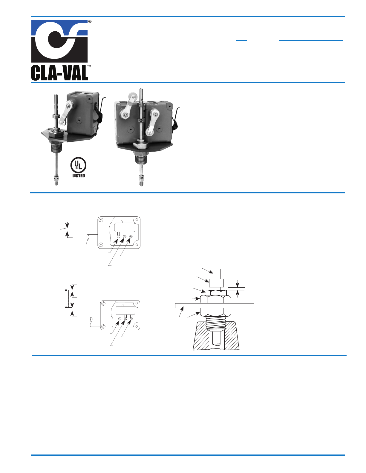
Limit Switch Assemblies
Switches shown in
unactivated position.
Double Pole Double Throw Switch
Single Pole Double Throw Switch
Installation
Actuating Collar Adjustment
Minimum Setting
When adjusting actuating collar for
proper switch action, a clearance of
at least 1/16" (1/8” for 48” valve)
must be provided between the
collar and the bushing gland nut
when valve is in the fully closed
position.
1. Remove plug in top of valve cover.
2. Screw actuating stem into main valve stem.
3. Slip adapter down over stem and screw into place on valve cover.
4. Attach micro switch housing and bracket to adapter with jam nut.
5. Bring electrical supply circuit into unit through the 1/2" tapping in micro switch
housing.
6. Adjust switch collars. (Set collar to trip switch after valve is positioned fully open
or fully closed)
• UL Listed Switches
• Positive Action
• Rugged and Dependable
• Weather Proof or Explosion Proof
• Easy To Adjust
The Cla-Val Model X105L/X105L2 Limit Switch Assembly is a
rugged, dependable and positive acting switch assembly actuated
by the opening or closing of a Cla-Val control valve on which it is
mounted. The single pole, double throw micro switch can be
connected either to open or to close an electrical circuit when
actuated. By loosening the allen screw on the actuating collar and
raising or lowering the collar on the stem, the X105L is easily
adjusted to signal that the valve has fully reached the desired
position (open or closed).
X105L
X105L2
MODELS
COM
N.C.
N.O.
Circuit Diagram
of Single Pole
Double Throw
Switch
Common
Lug
Normally
Closed
Normally
Open
N.C.
N.C.
N.O.
COM
COM
Circut Diagram
of Single Pole
Double Throw
Switch
Normally
Closed
Normally
Open
Common Lug
N.O.
Stem
Bushing Gland Nut
Jam Nut
Bracket
Switch Actuating Collar
Adapter
Min.
1/16"
Switch only
Purchase Specifications
The assembly shall be bracket-mounted to exterior of an adapter attached to the center of the main valve cover. A stainless steel
actuating stem with a swivel adapter shall be fastened directly to the main valve stem and move vertically through an adapter and
gland with two O-ring seals as the valve moves. An adjustable collar located on the actuating stem shall actuate the sensor arm of a
switch when valve has fully reached the open or closed (specify) position. The rotary-type position sensor arm shall actuate SPDT or
DPDT type (specify) micro-switches mounted inside protective housing either weather-tight or explosion-proof NEMA rated (specify).
Provisions shall be made for bleeding air from valve cover through a small bleed screw and washer located on one wrench flat of
adapter. All assemblies shall be capable of accommodating up to three switches. Standard materials in contact with operating fluid
are brass, stainless steel, Monel and Buna-N.
A conduit hub opening in the switch enclosure shall be provided for attaching protective weatherproof conduit for the electrical switch
wires (wiring and conduit supplied by others). A sealing plug shall be provided to protect conduit opening during shipping or storage.
Page 23

X105 Series Dimensions
(In Inches)
A
Fig. 1
Valve Size
1 1/4" Thru 8"
X105L2W
X105L2X
1/2-14 N.P.S.M. Thread
(Conduit Connections)
.13
2.44
1.70
3.00
.86
3.13
2.00
C (Typical)
Fig. 2
Valve Size
1 1/4" Thru 24"
X105LCW
X105LCX
A
Fig. 4
Valve Size
10" Thru 24"
X105LOW
X105LOX
A
B
Fig. 3
Valve Size
1 1/4" Thru 8"
X105LOW
X105LOX
A
Fig. 5
Valve Size
10" Thru 24"
X105L2W
X105L2X
B
A
BasicValve 100-01 1 1⁄4 1 1⁄2 2 2 1⁄2 3 4 6 8 10 12 14 16 18 20 24 30 36* 42* 48*
Dimension "A" 10.19 10.19 7.16 7.16 7.34 7.00 6.69 6.91 9.88 9.59 9.16 10.78 10.78 18.23 19.10 35.07 36.07 36.07 36.07
Dimension "B" 1.69 1.69 2.44 2.94 2.94 2.94 2.94 4.32 5.19 8.40 8.40 8.40 8.40
C (NPT) 1/4 1/4 1/2 1/2 1/2 3/4 3/4 1 1 1 1/4 1 1/2 2 2 3/4 3/4 2 2 2 2
BasicValve 100-20 3 4 6 8 10 12 14 16 18 20 24 30 36* 42* 48*
Dimension "A" 7.16 7.34 7.00 6.69 6.91 9.88 9.59 9.59 10.78 10.78 10.78 11.30 35.07 36.07 36.07
Dimension "B" 1.69 1.69 2.44 2.94 2.94 2.94 2.94 2.94 5.19 8.40 8.40 8.40
C (NPT) 1/2 1/2 3/4 3/4 1 1 1 1/4 1 1/4 2 2 2 1 2 2 2
A
Max
Top surface
of cover
20” & 24” Size
X105LCW & X105LCX
20” & 24” Size
X105LOW
Top surface
of cover
A
Max
B
C (NPT)
Valve Stem
1-11 1/2NPT
Insert 3/32” Dia. Rod
in this hole to turn
stem assembly into
valve stem
20” & 24” Size
X105L2W
Top surface
of cover
A
Max
B
C (NPT)
Housing,
Cover Bearing
A **
A* - 30” • A** - 36”, 42” & 48” Size
A *
1.00
2.75
B
12.00
28.13
30
” Stem
7.50
30” Stroke
8.50
36” - 48”
Stroke
7.50 Stroke
8.50 Stroke
Page 24

Limit Switch Assembly
11
10
1
2
5
7
6
8
4
3
9
12
VALV E
COVER
13
When ordering parts,
please specify:
• Item Number
• Description
• Part Number
X105L
PARTS LIST
COVER
12
9
15
16
Item
Part
Number
Description
Valves Sizes
Used On
1-2 20441701E Collar W/Set Screw All
3 67578-21B Screw, Machine (2) All
4 67584-23F Washer, Lock (2) All
5 34637K
Switch Assembly,
Weather Proof
All
34633J
Switch Assembly,
Explosion Proof
All
6 64310G
Bracket
Switch Mounting
10" thru 16"
7 67815-06J Nut, Jam All
8 63674G Plate, Mounting All
9
2838201J
2838202G
Adapter
Adapter
2" thru 3"
4" thru 16"
10 63398C
Bushing, Gland
All
11 00951E O-Ring (2) All
12
6764417K
6764418H
6764419F
6764491J
Bushing
Bushing
Bushing
Bell Reducer
8" and 10"
12"
14"
16"
13
8970101F
8970102D
8970103B
8970104K
8970105G
Stem, Actuating
Stem, Actuating
Stem, Actuating
Stem, Actuating
Stem, Actuating
2"-2 1/2"
3"-4"
6"-8"
10"-12"-14"
16"
15 6551201H Fiber Washer All
16 6824421K Screw 8-32 x 3/8 All
Parts list shown is for sizes 16” and smaller.
Please consult factory for parts on sizes 18”,
20”, 24”, 30”, 36”, 42” and 48”.
Page 25
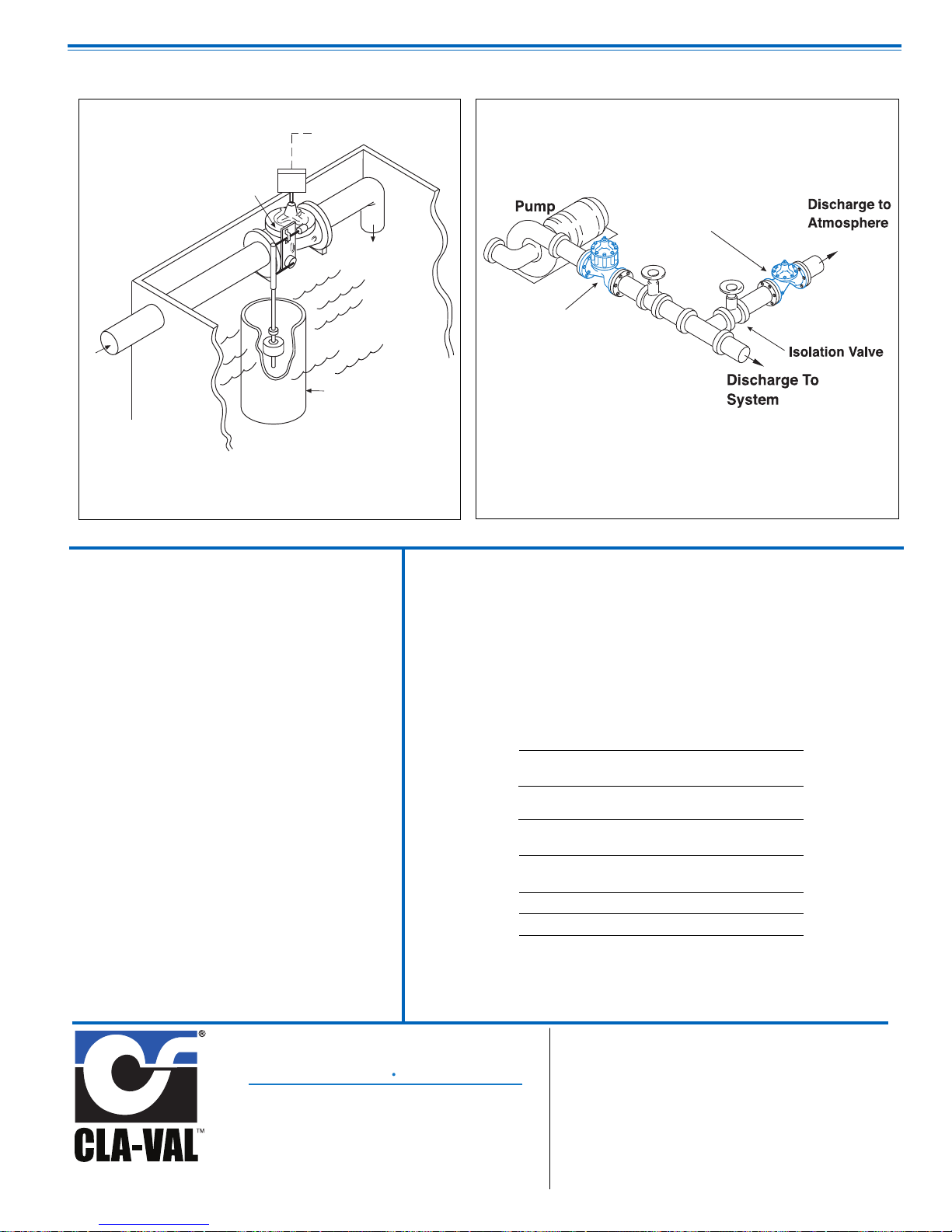
E-X105L/X105L2 (R-11/2015)
1701 Placentia Ave. Costa Mesa, CA 92627-4475
Phone: 949-722-4800 Fax: 949-548-5441
C
LA-VAL
CLA-VAL CANADA CLA-VAL EUROPE
4687 Christie Drive
Beamsville, Ontario
Canada L0R 1B4
Phone: 905-563-4963
Fax: 905-563-4040
Chemin dés Mesanges 1
CH-1032 Romanel/
Lausanne, Switzerland
Phone: 41-21-643-15-55
Fax: 41-21-643-15-50
©COPYRIGHT CLA-VAL 2015 Printed in USA
Specifications subject to change without notice.
www.cla-val.com
Represented By:
1. Valve Size and Basic Valve Model
Number
2. Catalog Number from Table Below
3. All Valve Name Plate Data
4. Select Single or Double Pole Switch
5. Explosion Proof or Weather
Proof Type Enclosure
6. Amperes and Voltage, AC or DC
7. Actuating Position (Valve Open or
Closed)
CATALOG ACTUATION SWITCH
NO. POSITION ENCLOSURE
X105LCW Valve Weather Proof
Closed
X105LCX Valve Explosion Proof
Closed
X105LOW Valve Weather Proof
Open
X105LOX Valve Explosion Proof
Open
X105L2W Dual Weather Proof
X105L2X Dual Explosion Proof
Specifications
Materials: Aluminum switch housing
Steel bracket and brass adapter
Stainless steel stem
Electrical: 1/2" Conduit connection
Switch Type: SPDT UL, File No. E12252,
CSA Certified, File No. LR57325
Weather proof
NEMA 1,3,4, and13
Switch Rating: UL/CSA rating: L96
15 amp. 125, 250, or 480 volts AC
1/2 amp. 125 volts DC
1/4 amp. 250 volts DC
Switch Options: DPDT switches available on request
UL/CSA Rating: L59, 10 amps
Explosion proof micro switches are
NEMA 1,7, and 9
UL Listed, File No. E14274 and CSA
Certified, File No. LR57324: Class I,
Group C and D and Class II, Group
E, F and G.
When Ordering, Please Specify
Supply
Tank
Stilling Well
CLA-VAL
124 Series
Float Valve
Annunciator
Used for any electrical operation which can be performed by
either opening or closing a switch; such as alarm systems,
process control, pump control, motor starting or stopping,
etc. Readily attached to most Cla-Val Valves.
Typical Applications
CLA-VAL 60 Series
Booster Pump
Control Valve
CLA-VAL 50 Series
Pressure Relief Valve
The X105L Series Limit Switch Assembly is used on Cla-Val 60
Series Booster Pump Control Valves. Flexible conduit is used for
electrical connections to the solenoid control and the limit switch.
Page 26

Limit Switch Assembly
11
10
1
2
5
7
6
8
4
3
9
12
VALV E
COVER
13
When ordering parts,
please specify:
• Item Number
• Description
• Part Number
X105L
CLA-VAL
Copyright Cla-Val 2011 Printed in USA Specifications subject to change without notice.
P.O. Box 1325 • Newport Beach, CA 92659-0325 • Phone: 949-722-4800 • Fax: 949-548-5441 • E-mail: claval@cla-val.com • Website cla-val.com
©
PL- X105L (R-3/2011)
PARTS LIST
COVER
12
9
15
16
Item
Part
Number
Description
Valves Sizes
Used On
1-2 20441701E Collar W/Set Screw All
3 67578-21B Screw, Machine (2) All
4 67584-23F Washer, Lock (2) All
5 34637K
Switch Assembly,
Weather Proof
All
34633J
Switch Assembly,
Explosion Proof
All
6 64310G
Bracket
Switch Mounting
10" thru 16"
7 67815-06J Nut, Jam All
8 63674G Plate, Mounting All
9
2838201J
2838202G
Adapter
Adapter
2" thru 3"
4" thru 16"
10 63398C
Bushing, Gland
All
11 00951E O-Ring (2) All
12
67644-17K
67644-18H
67644-19F
67644-91J
Bushing
Bushing
Bushing
Bell Reducer
8" and 10"
12"
14"
16"
13
89701-01F
89701-02D
89701-03B
89701-04K
89701-05G
Stem, Actuating
Stem, Actuating
Stem, Actuating
Stem, Actuating
Stem, Actuating
2"-2 1/2"
3"-4"
6"-8"
10"-12"-14"
16"
15 6551201H Fiber Washer All
16 6824421K Screw 8-32 x 3/8 All
Page 27

Model CDC-1
Check Valve
Sizes 3/8” and 1/2”
Dimensions
CLA-VAL
1701 Placentia Ave • Costa Mesa CA 92627 • Phone: 949-722-4800 • Fax: 949-548-5441 • E-mail: info@cla-val.com • www.cla-val.com
Copyright Cla-Val 2017 • Printed in USA • Specifications subject to change without notice.
©
E-CDC-1 (R-06/2017)
Item Description Quantity
1 Retainer, Seal 1
2 O-Ring 1
3 Retainer, Valve 1
4 Seal, Valve Ring 1
5 Plate, Valve 1
Size
(NPT)
A B C
3/8" 2.06 1.06 .38 (3/8) - 18 NPT
1/2" 2.12 1.38 .50 (1/2) - 14 NPT
• NSF-61 Approved
• Meets Low Lead Requirements
• Patented Seal Design Allows for Drip Tight Shut-off
at Low DP
• No Spring Required due to Patented Seal Design
• Delrin® Disc with Flow Profile Designed to Minimize
Head Loss
• Delrin® Disc Resists Corrosion and/or Mineral
Build-up
• Drip Tight Seating at both Low and High Operating
Pressures
• Temperature Range: 10°F to 210°F
• EPR, NBR and Fluorocarbon Seal Options
C
C
A
B
Page 28

CLA-VAL
Copyright Cla-Val 2018 Printed in USA Specifications subject to change without notice.
1701 Placentia Ave • Costa Mesa CA 92627 Phone: 949-722-4800 • Fax: 949-548-5441 • E-mail: info@cla-val.com • www.cla-val.com
©
INSTALLATION / OPERATION / MAINTENANCE
Flow Control
CV
MODEL
N-CV (R-06/2018)
DESCRIPTION
The CV Control is an adjustable restriction which acts as a
needle valve when flow is in the direction of the stem. When
flow is in the reverse direction, the port area opens fully to
allow unrestricted flow. When installed in the control system of
a Cla-Val automatic valve, it can be arranged to function as
either an opening or closing speed control.
OPERATION
The CV Flow Control permits full flow from port A to B, and
restricted flow in the reverse direction. Flow from port A to B
lifts the disc from seat, permitting full flow. Flow in the reverse
direction seats the disc, causing fluid to pass through the clearance between the stem and the disc. This clearance can be
increased, thereby increasing the restricted flow, by screwing
the stem out, or counter-clockwise. Turning the stem in, or
clockwise reduces the clearance between the stem and the
disc, thereby reducing the restricted flow.’
INSTALLATION
Install the CV Flow Control as shown in the valve schematic
All connections must be tight to prevent leakage.
DISASSEMBLY
Follow the sequence of the item numbers assigned to the
parts in the cross sectional illustration for recommended
o
rder of disassembly.
Use a scriber, or similar sharp-pointed tool to remove O-ring
from the stem.
INSPECTION
Inspect all threads for damage or evidence of crossthreading. Check mating surface of seat and valve disc for
excessive scoring or embedded foreign particles. Check
spring for visible distortion, cracks and breaks. Inspect all
parts for damage, corrosion and cleanliness.
CLEANING
After disassembly and inspection, cleaning of the parts can
begin. Water service usually will produce mineral or lime
deposits on metal parts in contact with water. These
deposits can be cleaned by dipping the parts in a 5-percent
muriatic acid solution just long enough for deposits to dissolve. This will remove most of the common types of
deposits. Caution: use extreme care when handling
acid. If the deposit is not removed by acid, then a fine grit
(400) wet or dry sandpaper can be used with water. Rinse
parts in water before handling. An appropriate solvent can
clean parts used in fueling service. Dry with compressed air
or a clean, lint-free cloth. Protect from damage and dust
until reassembled.
REPAIR AND REPLACEMENT
Minor nicks and scratches may be polished out using a fine
grade of emery or crocus cloth; replace parts if scratches
cannot be removed.
Replace O-ring packing and gasket each time CV Flow
Control is overhauled.
Replace all parts which are defective. Replace any parts
which create the slightest doubt that they will not afford completely satisfactory operation. Use Inspection steps as a
guide.
REASSEMBLY
Reassembly is the reverse of disassembly; no special tools
are required.
TEST PROCEDURE
No testing of the flow Control is required prior to reassembly
to the pilot control system on Cla-Val Main Valve.
Page 29

3/8" Flow Control
CV
2.12
MAX
STAMP PART NO. ON
SMOOTH SURFACE
RESTRICTED
FLOW
3/8 - 18 NPT
1.84
ADJUSTING STEM
(TURN CLOCKWISE TO
INCREASE RESTRICTION)
1
7
2
10
9
8
6
5
4
3
.85
FREE FLOW
BAR STOCK
CONFIGURATION
When ordering parts,
please specify:
• Number Stamped on Side
• Description (CV Flow Control)
• Part Description
• Material
CLA-VAL
Copyright Cla-Val 2018 Printed in USA Specifications subject to change without notice.
1701 Placentia Ave • Costa Mesa CA 92627 Phone: 949-722-4800 • Fax: 949-548-5441 • E-mail: info@cla-val.com • www.cla-val.com
©
PL-CV (R-03/2011)
PARTS LIST
ITEM DESCRIPTION QTY
1
Cap (SS only)
1
2
Nut, Jam
1
3
Seat
1
4
Gasket
1
5
Disc
1
6
Spring
1
7
Ring, Retaining
1
8
Stem
1
9
O-Ring
1
10
Housing
1
Page 30
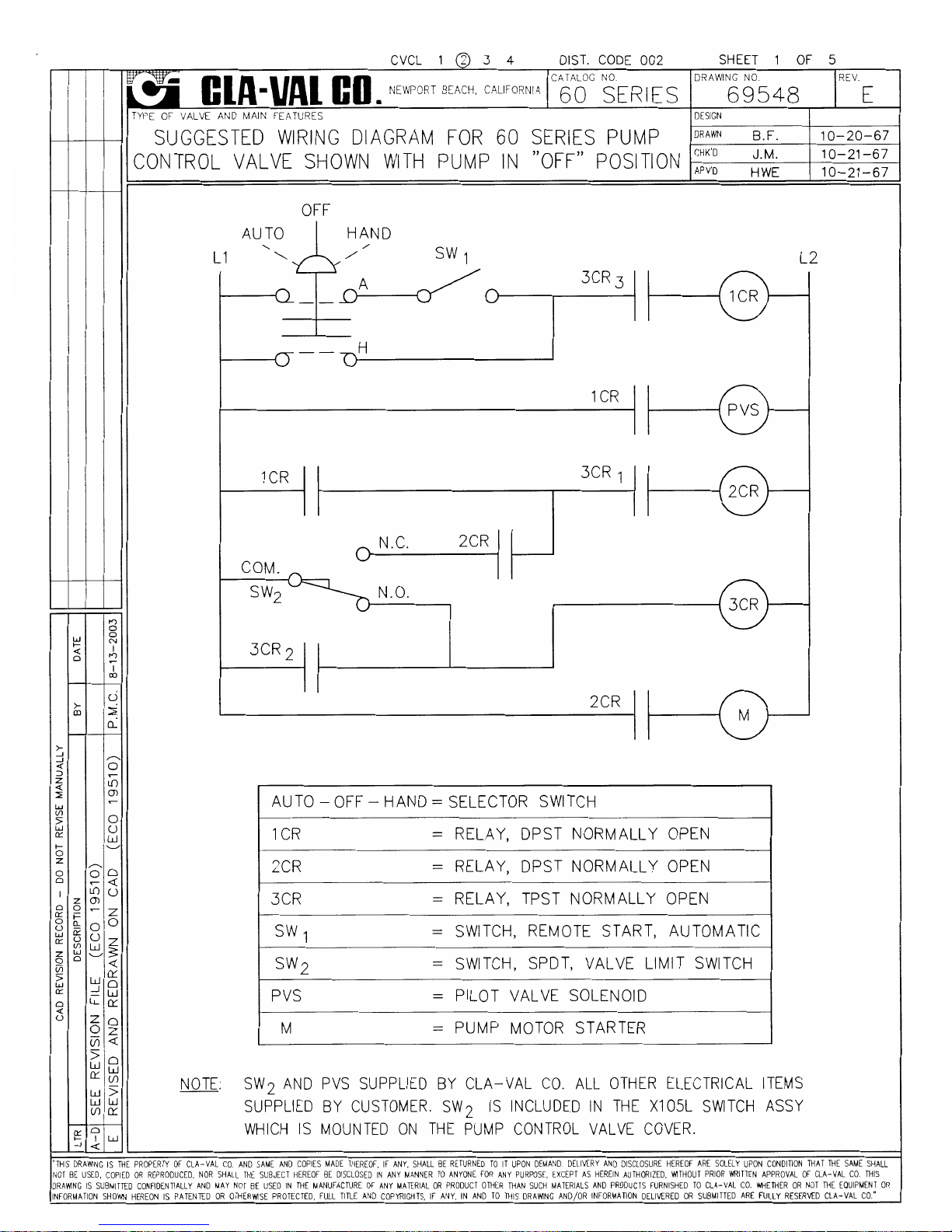
I')
0
w
0
N
I-
I
<(
Cl
I')
I
OC>
u
>-
~
Q)
n.:
>-
_J
,.........
_J
<(
0
:::i
ti)
z
<(
:::i:
(J)
..----
w
(/)
0
5
w
u
a:::
w
I-
'-../
0
z
,........
0
0
0
Cl
..----
<t:
I
L{)
u
z
(J)
Cl
0
..----
z
a:::
F
0
Q,,
0 0
u
w
5
Ulz
a:::
z
~
~
3:
0
Cl
<t:
in
0:::
5
w
0 w
_J
a:::
w
0
LL.
0:::
<(
u
z
0
0
z
Ui
<t:
>
0
w
O:'.:
w
(f)
w
>
w
w
(f)
O:'.:
a:::
Cl
I-
I w
_J
<(
CVCL
1 @ 3 4
DIST.
CODE
002
SHEET
1
OF
DRAWING
NO.
69548
l!j_
ClA·\/Al
CO.
NEwroRr
sEAcH.
c.uoRNIA
lc6QG
SERIES
TYPE
OF
VALVE
AND
MAIN
FEATURES
DESIGN
SUGGESTED
WIRING
DIAGRAM
FOR
60
SERIES
PUMP
CONTROL
VALVE
SHOWN
WITH
PUMP
IN
"OFF"
POSITION
DRAWN
CHK'D
APV'D
B.F.
J.M.
HWE
L1
NOTE:
OFF
AUTO
HAND
L2
t----e-
H
1CR
t----8-
1CR
t----8--
COM.
O N.C.
2CRl-
..--------8-
N.O.
2CR
AUTO -OFF -HAND=
SELECTOR
SWITCH
1CR
= RELAY, DPST NORMALLY
OPEN
2CR
= RELAY, DPST NORMALLY
OPEN
3CR
= RELAY,
TPST
NORMALLY
OPEN
=
SWITCH,
REMOTE
START, AUTOMATIC
=
SWITCH,
SPOT,
VALVE LIMIT
SWITCH
PVS
= PILOT
VALVE
SOLENOID
M
=
PUMP
MOTOR
STARTER
SW2
AND
PVS
SUPPLIED
BY
CLA-VAL
CO.
ALL
OTHER
ELECTRICAL
ITEMS
SUPPLIED
BY
CUSTOMER.
SW 2 IS
INCLUDED
IN
THE
X105L
SWITCH
ASSY
WHICH
IS
MOUNTED
ON
THE
PUMP
CONTROL
VALVE
COVER.
5
IREV.E
10-20-67
10-21-67
10-21-67
"THIS
DRAWING
IS
THE
PROPERTY
OF
CLA-VAL
CO.
AND
SAME
AND
COPIES
MADE
THEREOF,
IF
ANY,
SHALL
BE
RETURNED
TO
IT
UPON
DEMAND
DELIVERY
AND
DISCLOSURE
HEREOF
ARE
SOLELY
UPON
CONDITION
THAT
THE
SAME
SHALIL
NOT
BE
USED,
COPIED
OR
REPRODUCED,
NOR
SHALL
THE
SUBJECT
HEREOF
BE
DISCLOSED
IN
ANY
MANNER
TO
ANYONE
FOR
ANY
PURPOSE,
EXCEPT
AS
HEREIN
AUTHORIZED,
WITHOUT
PRIOR
WRITTEN
APPROVAL
OF
CLA-VAL
CO.
THIS
DRAl'l1NG
IS
SUBMITTED
CONFIDENTIALLY
AND
MAY
NOT
BE
USED
IN
THE
MANUFACTURE
OF
ANY
MATERIAL
OR
PRODUCT
OTHER
THAN
SUCH
MATERIALS
AND
PRODUCTS
FURNISHED
TO
CLA-VAL
CO.
1'11HETHER
OR
NOT
THE
EQUIPMENT
OR
INFORMATION
SHOWN
HEREON
IS
PATENTED
OR
OTHERWISE
PROTECTED.
FULL
TITLE
AND
COPYRIGHTS,
IF
ANY,
IN
AND
TO
THIS
DRAWING
AND/OR
INFORMATION
DELIVERED
OR
SUBMITTED
ARE
FULLY
RESERVED
CLA-VAL
co."
Page 31

>--
::]
...:::
:::J
:z
...:::
::::::;;:
w
U1
5
w
0:::
r-
I=!
...:::
=
>--
co
~
6
0 f=:
= o._
15
=
U1
gs
2:5
(.J
w
oc
:z
0
Vi
5
w
oc
a
...:::
(.J
f--
w
w
I
if)
w
w
if)
CVCL 1
(bl
3 4 DIST
CODE
002
SHEET
2
OF
5
DRAV!1NG
NO.
I
REV
69548
E
l!1i
ClA·\IAl
CO.
NEWPORT
BEACH.
CALIFORNIA
ICA60NOSERIES
DESIGN
SUGGESTED
WIRING
DIAGRAM
FOR
60
SERIES
PUMP
CONTROL
VALVE
SHOWN
WITH
PUMP
IN
"OFF"
POSITION
DRAWN
B.F.
10-20-67
CHK'D
J.M.
10-21-67
APV'D
HWE
10-21-67
WIRING
DIAGRAM
EXPLANATION
THIS
SUGGESTED
WIRING
DIAGRAM
PROVIDES
ELECTRICAL
INTERLOCK
TO
PREVENT
SURGES
ON
START
UP & SHUT
DOWN
OF
ELECTRIC
MOTOR-DRIVEN
PUMPS.
IT
IS
SUITABLE
FOR
MOST
APPLICATIONS
OF
CLA-VAL 60 &
61
SERIES
PUMP
CONTROL
VALVES.
FOR
EXPLANATION
OF
HYDRAULIC
VALVE
OPERATION
AND
PUMP
STARTING-STOPPING
SURGE
PROTECTION
SEQUENCE,
SEE
CATALOG
DATA
SHEET
FOR
60
SERIES
BOOSTER
PUMP
CONTROL
VALVES
(e.g.
-E-60-11,
ETC)
OR
61
SERIES
DEEP
WELL
PUMP
CONTROL
VALVES
(e.g.
-E-61-02,
ETC).
PUMP
OFF
THE
PUMP
CONTROL
VALVE
WILL
BE
IN
ITS
HYDRAULICALLY
NORMALLY
OPEN
(FOR
61
SERIES
VALVES)
OR
NORMALLY
CLOSED
(FOR
60
SERIES
VALVES)
POSITION.
SW2
IS
MOUNTED
ON
THE
PUMP
CONTROL
VALVE
AND
IS
IN
THE
OPEN
POSITION
(N.O.)
WHEN
THE
PUMP
IS
OFF.
3CR
RELAY
IS
ENERGIZED
AND
ALL
OF
IT'S
CONTACTS
ARE
CLOSED.
AUTO-OFF-HAND
SWITCH
ALLOWS
SELECTION
OF
THREE
MODES.
AUTO
OR
AUTOMATIC
MODE
SIGNALS
PUMP
ON
AND
OFF
UNDER
COMMAND
OF
REMOTE
SWITCH
SW1.
THIS
COULD
BE
ANY
REMOTE
SWITCH
FROM A SIMPLE
PRESSURE
SWITCH
TO A COMPLEX
COMPUTER
SYSTEM
SWITCH.
HAND
MODE
ALLOWS
OVERRIDING
THE
AUTO
MODE
FOR
THOSE
TIMES
WHEN
IT
IS
NECESSARY
TO
MANUALLY
(AT
THE
PANEL)
SIGNAL
THE
PUMP
TO
START
(HAND)
AND
STOP
(OFF).
OFF
AUTO
HAND
......
/
SW
1
L1
...........
/
L2
--
3CR3
e-
(CLOSED)
H
1CR
i-------18-
3CR
1
e-
i------------r------+---------1
2CR
(CLOSED)
1CR
2CR
I
1--------e--
I
(ENERGIZED)
3CR2
,___
__________
_.__!
- - - -
..J
(CLOSED)
2CR
"THIS
DRA'MNG
IS
THE
PROPERTY
OF
CLA-VAL
CO.
AND
SAME
AND
COPIES
MADE
THEREOF,
IF
ANY,
SHALL
BE
RE1URNED
TO
IT
UPON
DEMAND.
DELIVERY
AND
OISCLOSURE
HEREOF
ARE
SOLELY
UPON
CONDlnON
THAT
THE
SAME
SHALL
NOT
BE
USED,
COPIED
OR
REPRODUCED,
NOR
SHALL
THE
SUBJECT
HEREOF
BE
DISCLOSED
IN
ANY
MANNER
TO
ANYONE
FOR
ANY
PURPOSE,
EXCEPT
AS
HEREIN
AUTHORIZED,
WITHOUT
PRIOR
WRITTEN
APPROVAL
OF
CLA-VAL
CO.
THIS
DRAWING
IS
SUBMITTED
CONFIDENTIALLY
AND
MAY
NOT
BE
USED
IN
THE
MANUFACTURE
OF
ANY
MATERIAL
OR
PRODUCT
OTHER
THAN
SUCH
MATERIALS
AND
PRODUCTS
FURNISHED
TO
CLA-VAL
CO.
l'IHETHER
OR
NOT
THE
EQUIPMENT
OR
INFORMATION
SHOWN
HEREON
IS
PATENTED
OR
OTHERWISE
PROTECTED,
FULL
TITLE
AND
COPYRIGHTS,
IF
ANY,
IN
AND
TO
THIS
DRAWING
AND/DR
INFORMATION
DELIVERED
OR
SUBMITTED
ARE
FULLY
RESERVED
CLA-VAL
CO"
Page 32

>-
:::J
<C
:::>
:z:
<C
::::;:
LI...J
(/)
5
LI...J
0:::
!--
>-
CD
~~
0
t=
Cl
Q_
1§
Cl
(/)
gs
~
u
LI...J
0:::
:z
0
U'i
5
LI...J
0:::
~
t-
u w
w
:r:
(/)
0:::
1--
_J
w
w
(/)
CVCL 1 @ 3 4
DIST
CODE
002
~
ClA·\IAl
CO.
NEWPORT
BEACH,
CALIFORNIA
ICA60NOSERIES
SUGGESTED
WIRING
DIAGRAM
FOR
60
SERIES
PUMP
CONTROL
VALVE
SHOWN
WITH
PUMP
IN
"OFF"
POSITION
PUMP
SIGNALED
TO
GO
"ON"
USING
"AUTO"
MODE
SHEET
3
OF
5
DRA\\ING
NO.
I
REV
E
69548
DESIGN
DRAVv'N
8.F.
10-20-67
CHK'D
J.M.
10-21-67
APV'D
HWE
10-21-67
STEP
1:
SELECTOR
SWITCH
IS
TURNED
TO
AUTO
POSITION.
ELECTRICITY
FROM
L1
GOES
THROUGH
THE
SWITCH
TO
TERMINAL A AND
TO
SW1.
WHEN A REMOTE
PRESSURE
SWITCH
OR
OTHER
ELECTRICAL
SWITCH
CLOSES
SW1,
ELECTRICITY
GOES
THROUGH
3CR3
(ALREADY
CLOSED),
AND
ENERGIZES 1 CR
COIL
AND
CLOSES
ITS
CONTACTS.
STEP
2:
WHEN 1 CR
CONTACTS
CLOSE,
PVS
IS
ENERGIZED
AND
SHIFTS
PORTS
CAUSING
THE
PUMP
CONTROL
VALVE
TO
BEGIN
MOVING.
AT
THE
SAME
TIME
1
CR
ENERGIZED
THE
PVS
COIL, I TS
SECOND
SET
OF
CONT
ACTS
CLOSED
WHICH
ALLOWED
ELECTRICITY
TO
GO
FROM
L 1
THROUGH 1 CR
AND
3CR1
TO
ENERGIZE
RELAY
2CR.
STEP
3:
WHEN
2CR
RELAY
IS
ENERGIZED,
ITS
FIRST
SET
OF
POINTS
CLOSE
AND
COMPLETE
THE
CIRCUIT
FROM
L 1
THROUGH
THE
N.C.
TERMINAL
OF
SW1
AND
3CR1.
AT
THE
SAME
TIME,
ITS
SECOND
SET
OF
POINTS
CLOSE,
WHICH
ALLOWS
ELECTRICITY
FROM
L 1
THROUGH
2CR
TO
THE
PUMP
MOTOR
STARTER.
THIS
STARTS
THE
PUMP
AND
COMPLETES
THE
CIRCUIT
TO
L2.
OFF
THE
PUMP
IS
NOW
ON
AUTO
HAND
' /
L1
"-
/
L2
A
SW
1
3CR
3 t J::::\_
STEP
1
----Q_
__
D----0-----0---r---
--~~D~-
-
-D~H------~-
1CR
e-
1--~~~~~~~~~~~~~~~~----~----PVS
(CLOSES)
STEP
2
(ENERGIZED)
-(CL~~E:)
H-----------,-
3
c~
1
~t---e---
~
~
I
(ENERGIZED)
N.C.
2CR
_J
_~OM~~
Q--'-
-
(CLOSES
-
SW2
N.O.
e--
(ENERGIZED)
STEP
3
-----------------(cL~~E:~t---0--
FIG
2 (STARTS)
"THIS
DRAWING
IS
THE
PROPERTY
OF
CLA-VAL
CO.
AND
SAME
AND
COPIES
MADE
THEREOF,
IF
ANY,
SHALL
BE
RETURNED
TO
IT
UPON
DEMAND.
DELIVERY
AND
DISCLOSURE
HEREOF
ARE
SOLELY
UPON
CONDITION
THAT
THE
SAME
SHALL
NOT
BE
USED,
COPIED
OR
REPRODUCED,
NOR
SHALL
THE
SUBJECT
HEREOF
BE
DISCLOSED
IN
ANY
MANNER
TO
ANYONE
FOR
ANY
PURPOSE,
EXCEPT
AS
HEREIN
AUTHORIZED,
WITHOUT
PRIOR
~ITTEN
APPROVAL
OF
CLA-VAL
CO.
THIS
DRAWING
IS
SUBMITTED
CONFIDENTIALLY
AND
MAY
NOT
BE
USED
IN
THE
MANUFACTURE
OF
ANY
MATERIAL
OR
PRODUCT
OTHER
THAN
SUCH
MATERIALS
AND
PRODUCTS
FURNISHED
TO
QA-VAL
CO.
'MjETHER
OR
NOT
THE
EQUIPMENT
OR
INFORMATION
SHO'M<
HEREON
IS
PATENTED
OR
OTHERWISE
PROTECTED,
FULL
TITLE
AND
COPYRIGHTS,
IF
ANY,
IN
AND
TO
THIS
DRAWING
AND/OR
INFORMATION
DELIVERED
OR
SUBMITTED
ARE
FULLY
RESERVED
CLA-VAL
CO."
Page 33

>-
_J
_J
<C
:::::>
:z
<C
:::::;:
LW
(/)
5
LW
Cl:::
1---
>-
CD
~~
0
i=
Cl
o._
15
Cl
(/)
gs
~
u
LW
Cl:::
:z
0
U1
5
LW
Cl:::
Cl
<C
u
Cl:::
1---
_J
1-
w
w
:r:
(/)
w
w
(/)
CVCL 1
(2)
3 4 DIST
CODE
002
SHEET 4
OF
5
iff
__
C_lA~\l~
1
ftLC_D~~~-lcAT~ALOG~No.
___
---4-oRA~N~GNo.~~lRE~vE~
~
•
,..
•
NEWPORT
BEACH,
CALIFORNIA
60
SERIES
69548
DESIGN
SUGGESTED
WIRING
DIAGRAM
FOR
60
SERIES
PUMP
DRAVvN
8.F.
10-20-67
CONTROL
VALVE
SHOWN
WITH
PUMP
IN
"OFF"
POSITION
t-cA_HPKv:-
0
° _H_J.WM_E·--+---
10
---21---
67
---1
10-21-67
PUMP
SIGNALED
TO
GO
"OFF"
USING
"AUTO"
MODE
STEP
1:
REMOTE
SWITCH
SW1
OPENS
AND
DE-ENERGIZES
THE
COIL
OF 1 CR
RELAY
AND
ALL 1 CR
CONTACTS.
STEP
2:
THE
FIRST
SET
OF
CONTACTS
OF 1 CR
OPEN
AND
STOP
THE
ELECTRICITY
TO
THE
COIL
OF
PVS.
PVS
SHIFTS
PORTS
CAUSING
THE
PUMP
CONTROL
VALVE
TO
BEGIN
MOVING.
AT
THE
SAME
TIME
THE
SECOND
SET
OF
CONTACTS
TO
2CR
COIL
OPEN.
2CR
IS
HELD
ENERGIZED
BY
CONNECTION
TO
L 1
THROUGH
SW2.
STEP
3:
WHEN
THE
PUMP
CONTROL
VALVE
HYDRAULICALLY
REACHES
ITS
DE-ENERGIZED
POSITION
(SEE
PUMP
OFF
STEP,
ABOVE)
IT
MOVES
SW2
FROM
N.C.
CONTACT
TO
N.O.
CONTACT
AND
STOPS
ELECTRICITY
TO
2CR
COIL.
2CR
DE-ENERGIZES
AND
OPENS
ITS
CONTACTS,
WHICH
IN
TURN
DE-ENERGIZES
PUMP
MOTOR
STARTER
AND
SHUTS
PUMP
OFF.
THE
PUMP
IS
NOW
OFF
OFF
AUTO
HAND
' /
L1
........._
/
SW
1
L2
STEP
1
A
//
3CR3l
~
- -
--Q_
__
_0-
-----cY
0-
-
-r-
-
-r-
-
(DE~ED)-
- -
D,__H
________
--1_
------------------~;:~~---e---
STEP
2
(DE-ENERGIZED)
1CR
(OPENS)
f'\._N.C.
2CR~
~-----
(OPENS)
(DE-ENERGIZED)
N.O.
STEP
3
------------------co:E~)~
~--0--
(STOPS)
"THIS
DRA'MNG
IS
THE
PROPERTY
OF
CLA-VAL
CO
AND
SAME
AND
COPIES
MADE
THEREOF,
IF
ANY,
SHALL
BE
RETURNED
TO
IT
UPON
DEMAND.
DELIVERY
AND
DISCLOSURE
HEREOF
ARE
SOLELY
UPON
CONDITION
THAT
THE
SAME
SHALL
NOT
BE
USED,
COPIED
OR
REPRODUCED,
NOR
SHALL
THE
SUBJECT
HEREOF
BE
DISCLOSED
IN
ANY
MANNER
TO
ANYONE
FOR
ANY
PURPOSE,
EXCEPT
AS
HEREIN
AUTHORIZED,
'MTHOUT
PRIOR
VIRITTEN
APPROVAL
OF
CLA-VAL
CO.
THIS
DRA'MNG
IS
SUBMITTED
CONFIDENnALLY
AND
MAY
NOT
BE
USED
IN
THE
MANUFACTURE
OF
ANY
MATERIAL
OR
PRODUCT
OTHER
THAN
SUCH
MATERIALS
AND
PRODUCTS
FURNISHED
TO
CLA-VAL
CO.
'M-IETHER
OR
NOT
THE
EQUIPMENT
OR
INFORMATION
SHO'MN
HEREON
IS
PATENTED
OR
OTHER'MSE
PROTECTED,
FULL
TITLE
AND
COPYRIGHTS,
IF
ANY,
IN
AND
TO
THIS
DRA'MNG
AND/OR
INFORMATION
DELIVERED
OR
SUBMITTED
ARE
FULLY
RESERVED
CLA-VAL
CO."
Page 34

>-
:::J
<t:
=>
:z:
<t:
::::::E
LI..J
Vl
5
LI..J
0:::
t-
>-
cc
~
6
OF
Cl
CL
1§
Cl
Vl
gs
~
u
LI..J
0:::
6
Vi
5
LI..J
0:::
Cl
<t:
u
0:::
t-
~
:I
w
w
I
(/)
w
w
(/)
CVCL
1
(2)
3 4
DIST
CODE
002
SHEET
5
OF
5
DRA\IANG
NO.
I
REV
69548
E
r
ff
ClA
''"l
CO
!CATALOG
NO.
~
•
Utt
.
NEWPORT
BEACH,
CALIFORNIA
6 0 s
ER
I Es
DESIGN
SUGGESTED
WIRING
DIAGRAM
FOR
60
SERIES
PUMP
CONTROL
VALVE
SHOWN
WITH
PUMP
IN
"OFF"
POSITION
DRAWN
B.F.
10-20-67
CHK'D
J.M.
10-21-67
APV'D
HWE
10-21-67
2CR
RELAY
THIS
RELAY
IS
VERY
IMPORTANT
AND
SHOULD
BE
WIRED
EXACTLY
AS
SHOWN.
THE
MAIN
FUNCTION
OF
THIS
RELAY
IS
TO
HOLD
PUMP
"OFF"
WHEN
SELECTOR
SWITCH
OR
SW1
REMOTE
SWITCH
HAS
TOLD
PUMP
TO
GO
"OFF".
IF
WIRED
WRONG,
THE
PUMP
WILL
CYCLE
ON-OFF-ON-OFF.
WHEN
THE
SW2
MICRO
SWITCH
ARM
OF
X105
SWITCH
ASSEMBLY
IS
MOVED
EVER
SO
SLIGH
TY.
3CR
RELAY
THIS
RELAY
IS
THE
POWER
FAILURE
RELAY.
WHEN
NORMAL
POWER
IS
AVAILABLE,
3CR
IS
ENERGIZED
AND
THE
CONTACTS
ARE
CLOSED.
THIS
RELAY
IS
ENERGIZED
WITH
PUMP
ON
OR
PUMP
OFF.
DURING
NORMAL
PUMP
OPERATION
THE
3CR
CONTACTS
ARE
CLOSED.
BUT
WHEN
AN
INTERMITTENT
POWER
FAILURE
("BROWN
OUT")
OCCURS,
THIS
RELAY
DROPS
OUT
AND
ALL
OF
ITS
CONTACTS
OPEN.
WHEN
ELECTRIC
POWER
IS
QUICKLY
RE-ESTABLISHED,
THE
PUMP
WILL
NOT
COME
ON,
EVEN
THROUGH
SIGNALED
BY
SW1
"PUMP
AUTO
ON".
THIS
PREVENTS
THE
PUMP
FROM
RESTARTING
WITH A PARTIALLY
OPEN
PUMP
CONTROL
VALVE.
AFTER
THE
PUMP
CONTROL
VALVE
HAS
MOVED
HYDRAULICALLY
TO
ITS
NORMALLY
OPEN
(61
SERIES)
OR
NORMALLY
CLOSED
(60
SERIES)
POSITION,
IT
MOVES
SW2
TO
THE
OPEN
(N.O.)
POSITION.
THIS
LETS
ELECTRICITY
GO
FROM
L1
THROUGH
SW2
TO
ENERGIZE
COIL
OF
3CR
RELAY
AT
L2.
3CR
CONTACTS
CLOSE
AND
THE
CIRCUIT
WILL
THEN
BE
READY
FOR
"PUMP
SIGNALED
ON"
SEQUENCE
AS
IF
IT
WERE A NORMAL
SITUATION.
THE
3CR
RELAY
GIVES
THE
PUMP A "DELAYED
RESET"
APPEARANCE.
"THIS
DRA'MNG
IS
THE
PROPERTY
OF
CLA-VAL
CO.
AND
SAME
AND
COPIES
MADE
THEREOF,
IF
ANY,
SHALL
BE
RETURNED
TO
IT
UPON
DEMAND.
DELIVERY
AND
DISCLOSURE
HEREOF
ARE
SOLELY
UPON
CONDlnON
THAT
THE
SAME
SHALL
NOT
BE
USED,
COPIED
OR
REPRODUCED,
NOR
SHALL
THE
SUBJECT
HEREOF
BE
DISCLOSED
IN
ANY
MANNER
TO
ANYONE
FOR
ANY
PURPOSE,
EXCEPT
AS
HEREIN
AUTHORIZED,
'MTHOUT
PRIOR
'M'ITTEN
APPROVAL
OF
CLA-VAL
CO.
THIS
ORAViiNG
IS
SUBMITTED
CONFIDENTIALLY
AND
MAY
NOT
BE
USED
IN
THE
MANUFACTURE
OF
ANY
MATERIAL
OR
PRODUCT
OTHER
THAN
SUCH
MATERIALS
AND
PRODUCTS
FURNISHED
TO
CLA-VAL
CO.
v.iHETHER
OR
NOT
THE
EQUIPMENT
OR
INFORMATION
SHOWN
HEREON
IS
PATENTED
OR
OTHERl'!iSE
PROTECTED.
FULL
TITLE
AND
COPYRIGHTS.
IF
ANY,
IN
AND
TO
THIS
DRA'MNG
AND/OR
INFORMATION
DELIVERED
OR
SUBMITTED
ARE
FULLY
RESERVED
CLA-VAL
CO."
Page 35

CLA-VAL
Copyright Cla-Val 2011 Printed in USA Specifications subject to change without notice.
P.O. Box 1325 • Newport Beach, CA 92659-0325 • Phone: 949-722-4800 • Fax: 949-548-5441 • E-mail: claval@cla-val.com • Website cla-val.com
©
PL-CK2 (R-3/2011)
Page 36

The strainer is designed for use in conjunction with a Cla-Val
Main Valve, but can be installed in any piping system where
there is a moving fluid stream to keep it clean. When it is used
with the Cla-Val Valve, it is threaded into the upstream body port
provided for it on the side of the valve. It projects through the
side of the Main Valve into the flow stream. All liquid shunted to
the pilot control system and to the cover chamber of the Main
Valve passes through the X46 Flow Clean Strainer.
C
Male
Pipe
SAE
H
D
E
B
I
G
Male
Pipe
B
I
Width Across Flats
Female
Pipe
A
D
E
F
• Self Scrubbing Cleaning Action
• Straight Type or Angle Type
The Cla-Val Model X46 Strainer is designed to prevent passage of
foreign particles larger than .015". It is especially effective against
such contaminant as algae, mud, scale, wood pulp, moss, and root
fibers. There is a model for every Cla-Val. valve.
The X46 Flow Clean strainer operates on a velocity principle utilizing
the circular "air foil" section to make it self cleaning. Impingement of
particles is on the "leading edge" only. The low pressure area on the
downstream side of the screen prevents foreign particles from clogging the screen. There is also a scouring action, due to eddy currents, which keeps most of the screen area clean.
Dimensions
(In Inches)
INSTALLATION
X46 Angle Type B (In Inches)
B
(NPT)C(SAE)
DEH I
1/8 1/4 1-3/8 5/8 7/8 1/4
1/4 1/4 1-3/4 3/4 1 3/8
3/8 1/4 2 7/8 1 1/2
3/8 3/8 1-7/8 7/8 1 1/2
1/2 3/8 2-3/8 1 1-1/4 5/8
X46A Straight
X46B Angle
X46A Straight Type A (In Inches)
A B D E F G I
1/8 1/8 1-3/4 3/4 1/2 1/2 1/4
1/4 1/4 2-1/4 1 3/4 3/4 3/8
3/8 3/8 2-1/2 1 7/8 7/8 1/2
3/8 1/2 2-1/2 1-1/4 1/2 7/8 3/4
1/2 1/2 3 1-1/4 1 1-1/8 3/4
3/8 3/4 3-3/8 2 1/2 1 7/8
3/4 3/4 4 2 1 1-1/2 7/8
3/8 1 4-1/4 2-3/4 1/2 1-3/8 7/8
1 1 4-1/2 2-3/4 1-1/4 1-3/4 7/8
1/2 1 4-1/4 2-3/4 1/2 1-3/8 7/8
Flow Clean Strainer
X46
INSPECTION
Inspect internal and external threads for damage or evidence
of cross-threading. Check inner and outer screens for clogging,
embedded foreign particles, breaks, cracks, corrosion, fatigue,
and other signs of damage.
CLEANING
After inspection, cleaning of the X46 can begin. Water service usually will produce
mineral or lime deposits on metal parts in contact with water. These deposits can
be cleaned by dipping X46 in a 5-percent muriatic acid solution just long enough
for deposit to dissolve. This will remove most of the common types of deposits.
Caution: use extreme care when handling acid. If the deposit is not removed
by acid, then a fine grit (400) wet or dry sandpaper can be used with water.
Rinse parts in water before handling. An appropriate solvent can clean parts used
in fueling service. Dry with compressed air or a clean, lint-free cloth.
Protect from damage and dust until reassembled.
REPLACEMENT
If there is any sign of damage, or if there is the slightest doubt that the Model X46
Flow Clean Strainer may not afford completely satisfactory operation, replace it. Use
Inspection steps as a guide. Neither inner screen, outer screen, nor housing is furnished as a replacement part. Replace Model X46 Flow Clean Strainer as a complete unit.
When ordering replacement Flow-Clean Strainers, it is important to determine pipe
size of the tapped hole into which the strainer will be inserted (refer to column A or
F), and the size of the external connection (refer to column B or G).
When Ordering,
Please Specify:
• Catalog Number X46
• Straight Type or Angle Type
• Size Inserted Into and Size Connection
• Materials
DISASSEMBLY
Do not attempt to remove the screens from the strainer housing.
MODEL
INSTALLATION / OPERATION / MAINTENANCE
CLA-VAL
Copyright Cla-Val 2011 Printed in USA Specifications subject to change without notice.
P.O. Box 1325 • Newport Beach, CA 92659-0325 • Phone: 949-722-4800 • Fax: 949-548-5441 • E-mail: claval@cla-val.com • Website cla-val.com
©
N-X46 (R-3/2011)
(NPT) (NPT)
X46B
X46A
Page 37

CLA-VAL
1701 Placentia Ave • Costa Mesa CA 92627 • Phone: 949-722-4800 • Fax: 949-548-5441 • E-mail: info@cla-val.com • www.cla-val.com
Copyright Cla-Val 2017 • Printed in USA • Specifications subject to change without notice.
©
Cla-Val Gauge Option
E-X141 (R-08/2017)
X141
MODEL
Available Pressure Ranges
Typical Installation with two X141 Gauges
•
Liquid-Filled
•
Dual Scale (PSI / BAR)
•
Long Life Stainless Steel Construction
•
Tamper-Resistant Design
•
2 1⁄2" and 4" Diameter Sizes
•
Isolation Valve Included
The Cla-Val Model X141 Pressure Gauge Option consists of glycerin-filled pressure gauges with the Cla-Val Logo and 1⁄4” CK2
Bronze Isolation Valves on the main valve inlet and outlet. Cla-Val
gauges are waterproof, shock resistant, and fully enclosed with a
stainless steel case and bronze wetted parts.
Ambient temperature
ratings are -4 Degrees F to +140 Degrees F (-20 Degrees C to +60
Degrees C).
All gauges have dual scale (PSI/BAR) and are supplied with a 1/4"
NPT bottom connection. Model X141 gauges are available installed
on new valves and must be specified on the customer Purchase
Order. Consult factory for other available materials.
Model X141
4" Pressure Gauge
X141 Gauge Assembly (2 1/2" Diameter Dial)
Pressure Range* Part Number
0 - 60 psi 20534301 A
0 - 100 psi 20534302K
0 - 160 psi 20534311J
0 - 200 psi 20534303J
0 - 300 psi 20534304H
0 - 400 psi 20534305G
X141 Gauge Assembly (4" Diameter Dial)
Pressure Range* Part Number
0 - 60 psi 20534306F
0 - 100 psi 20534307E
0 - 200 psi 20534308D
0 - 300 psi 20534309C
0 - 400 psi 20534310K
Typical X141 Installation
*Specify desired pressure range and valve location (inlet or outlet) on order.
Page 38

1
2
3
4
5
3/8 NPT
Strainer
X43
Standard 60 mesh pilot system strainer for fluid service.
CLA-VAL
Copyright Cla-Val 2012 Printed in USA Specifications subject to change without notice.
P.O. Box 1325 • Newport Beach, CA 92659-0325 • Phone: 949-722-4800 • Fax: 949-548-5441 • E-mail: claval@cla-val.com • Website cla-val.com
©
PL- X43 (R-9/2012)
PARTS LIST
ITEM DESCRIPTION MATERIAL
1
Pipe Plug Steel
2
Strainer Plug Brass
3
Gasket Copper
4
Screen SST
5
Body Brass
No parts available. Rreplacement assembly only.
Size Stock Number
3/8 x 3/8 33450J
Page 39

Cla-Val Product
Identification
Proper Identification
For ordering repair kits, replacement parts, or for
inquiries concerning valve operation, it is important to
properly identify Cla-Val products already in service
by including all nameplate data with your inquiry.
Pertinent product data includes valve function, size,
material, pressure rating, end details, type of pilot
controls used and control adjustment ranges.
Identification Plates
For product identification, cast-in body markings are
supplemented by identification plates as illustrated on
this page. The plates, depending on type and size of
product, are mounted in the most practical position. It
is extremely important that these identification
plates are not painted over, removed, or in any
other way rendered illegible.
INLET
EINTRITT
ENTREE
ENTRADA
SIZE &
CAT NO.
STOCK
NO.
CODE
MFD. BY CLA-VAL
NEWPORT BEACH, CALIF, U.S.A.
RESERVOIR
END
I
N
L
E
T
I
N
L
E
T
SIZE &
CAT NO.
STOCK
NO.
FLOW
MFD. BY CLA-VAL NEWPORT BEACH, CALIF. U.S.A.
CODE
C
®
™
SIZE &
CAT NO.
STOCK
NO.
SPRING
RANGE
MFD. BY CLA-VAL NEWPORT BEACH, CALIF. U.S.A.
SIZE &
CAT NO.
STOCK
NO.
CODE
MFD. BY CLA-VAL
NEWPORT BEACH, CALIF.
U.S.A.
C
®
™
DO NOT REMOVE
THIS VALVE HAS BEEN MODIFIED
SINCE ORIGINAL SHIPMENT FROM
FACTORY. WHEN ORDERING PARTS
AND/ OR SERVICE SUPPLY DATA FROM
THIS PLATE & ALL OTHER PLATES ON
ORIGINAL VALVE.
REDUCED PRESSURE BACKFLOW PREVENTION DEVICE
STK.
NO.
SER.
NO.
CAT.
NO.
RP
-4
CLA-VAL
NEWPORT BEACH, CA.
This brass plate appears on valves sized 21/2" and larger
and is located on the top of the inlet flange.
These two brass plates appear on 3/8", 1/2", and 3/4" size
valves and are located on the valve cover.
These two brass plates appear on threaded valves
1" through 3" size or flanged valves 1" through 2".
It is located on only one side of the valve body.
This brass plate appears on altitude valves only and is
found on top of the outlet flange.
This brass plate is used to identify pilot control valves.
The adjustment range is stamped into the plate.
This tag is affixed to the cover of the pilot control valve.
The adjustment range appears in the spring range section.
This aluminum plate is included in pilot system
modification kits and is to be wired to the new pilot
control system after installation.
This brass plate is used on our backflow prevention
assemblies. It is located on the side of the Number Two
check (2" through 10"). The serial number of the
assembly is also stamped on the top of the inlet flange of
the Number One check.
How to Order
Page 40

HOW TO ORDER
Because of the vast number of possible configurations and
combinations available, many valves and controls are not
shown in published product and price lists. For ordering
information, price and availability on product that are not listed,
please contact your local Cla-Val office or our factory office
located at:
SPECIFY WHEN ORDERING
• Model Number • Valve Size
• Globe or Angle Pattern • Threaded or Flanged
• Adjustment Range • Body and Trim Materials
(As Applicable) • Optional Features
• Pressure Class
UNLESS OTHERWISE SPECIFIED
• Globe or angle pattern are the same price
• Ductile iron body and bronze trim are standard
• X46 Flow Clean Strainer or X43 “Y” Strainer are included
• CK2 Isolation Valves are included in price on 4" and larger
valve sizes (6" and larger on 600 Series)
P. O. Box 1325
Newport Beach, California 92659-0325
(949) 722-4800
FAX (949) 548-5441
LIMITED WARRANTY
Automatic valves and controls as manufactured by Cla-Val are warranted
for three years from date of shipment against manufacturing defects in
material and workmanship that develop in the service for which they are
designed, provided the products are installed and used in accordance
with all applicable instructions and limitations issued by Cla-Val.
Electronic components manufactured by Cla-Val are warranted for one
year from the date of shipment.
We will repair or replace defective material, free of charge, that is returned
to our factory, transportation charges prepaid, if upon inspection, the
material is found to have been defective at time of original shipment. This
warranty is expressly conditioned on the purchaser’s providing written
notification to Cla-Val immediate upon discovery of the defect.
Components used by Cla-Val but manufactured by others, are warranted
only to the extent of that manufacturer’s guarantee.
This warranty shall not apply if the product has been altered or repaired by
others, Cla-Val shall make no allowance or credit for such repairs or
alterations unless authorized in writing by Cla-Val.
DISCLAIMER OF WARRANTIES AND
LIMITATIONS OF LIABILITY
The foregoing warranty is exclusive and in lieu of all other
warranties and representations, whether expressed, implied, oral or
written, including but not limited to any implied warranties or
merchantability or fitness for a particular purpose. All such other
warranties and representations are hereby cancelled.
Cla-Val shall not be liable for any incidental or consequential loss,
damage or expense arising directly or indirectly from the use of the
product. Cla-Val shall not be liable for any damages or charges for
labor or expense in making repairs or adjustments to the product.
Cla-Val shall not be liable for any damages or charges sustained in
the adaptation or use of its engineering data and services. No
representative of Cla-Val may change any of the foregoing or
assume any additional liability or responsibility in connection with
the product. The liability of Cla-Val is limited to material
replacements F.O.B. Newport Beach, California.
TERMS OF SALE
ACCEPTANCE OF ORDERS
All orders are subject to acceptance by our main office at Newport Beach, California.
CREDIT TERMS
Credit terms are net thirty (30) days from date of invoice.
PURCHASE ORDER FORMS
Orders submitted on customer’s own purchase order forms will be accepted only
with the express understanding that no statements, clauses, or conditions contained
in said order form will be binding on the Seller if they in any way modify the Seller’s
own terms and conditions of sales.
PRODUCT CHANGES
The right is reserved to make changes in pattern, design or materials when deemed
necessary, without prior notice.
PRICES
All prices are F.O.B. Newport Beach, California unless expressly stated otherwise on
our acknowledgement of the order. Prices are subject to change without notice. The
prices at which any order is accepted are subject to adjustment to the Seller’s price
in effect at the time of shipment. Prices do not include sales, excise, municipal, state
or any other Government taxes. Minimum order charge $100.00.
RESPONSIBILITY
We will not be responsible for delays resulting from strikes, accidents, negligence of
carriers, or other causes beyond our control. Also, we will not be liable for any
unauthorized product alterations or charges accruing there from.
RISK
All goods are shipped at the risk of the purchaser after they have been delivered by
us to the carrier. Claims for error, shortages, etc., must be made upon receipt of
goods.
EXPORT SHIPMENTS
Export shipments are subject to an additional charge for export packing.
RETURNED GOODS
1. Customers must obtain written approval from Cla-Val prior to returning any
material.
2. Cla-Val reserves the right to refuse the return of any products.
3. Products more than six (6) months old cannot be returned for credit.
4. Specially produced, non-standard models cannot be returned for credit.
5. Rubber goods such as diaphragms, discs, o-rings, etc., cannot be returned for
credit, unless as part of an unopened vacuum sealed repair kit which is less
than six months old.
6. Goods authorized for return are subject to a 35% ($100 minimum) restocking
charge and a service charge for inspection, reconditioning, replacement of
rubber parts, retesting, repainting and repackaging as required.
7. Authorized returned goods must be packaged and shipped prepaid to Cla-Val,
1701 Placentia Avenue, Costa Mesa, California 92627.
PO Box 1325 Newport Beach CA 92659-0325
Phone: 949-722-4800 Fax: 949-548-5441
C
LA-VAL
CLA-VAL CANADA CLA-VAL EUROPE
4687 Christie Drive
Beamsville, Ontario
Canada L0R 1B4
Phone: 905-563-4963
Fax: 905-563-4040
Chemin dés Mesanges 1
CH-1032 Romanel/
Lausanne, Switzerland
Phone: 41-21-643-15-55
Fax: 41-21-643-15-50
©COPYRIGHT CLA-VAL 2011 Printed in USA
Specifications subject to change without notice.
www.cla-val.com
E-Product I.D. (R-3/2011)
Represented By:
Page 41

REPAIR KITS
MODEL
INSTALLATION / OPERATION / MAINTENANCE
BUNA-N MATERIAL
RUBBER KIT REPAIR KIT REBUILD KIT STUD & NUT KIT
STOCK NO. STOCK NO. STOCK NO. STOCK NO.
3/8” 9169801K 21176614B 21176633J
1/2” 9169802H 21176602F 21176615A 21176634H
3/4” 9169802H 21176602F 21176615A 21176634H
1” Non-Guided 9169803F 21176601G 21176616K 21176636F
1” 9169804D 21176603E 21176617J 21176636F
1 1/4” 9169804D 21176603E 21176617J 21176636F
1 1/2” 9169804D 21176603E 21176617J 21176636F
2” 9169805A 21176608K 21176618H 21176637E
2 1/2” 9169811J 21176609J 21176619G 21176638D
3” 9169812G 21176604D 21176620D 21176639C
4” 9169813E 21176605C 21176621C 21176640K
6” 9169815K 21176606B 21176622B 21176641J
8” 9817901D 21176607A 21176623A 21176642H
10” 9817902B 21176610F 21176624K 21176643G
12” 9817903K 21176611E 21176625J 21176644F
14” 9817904H 21176612D 21176626H 21176645E
16” 9817905E 21176613C 21176627G 21176645E
Consult factory for larger sizes
BUNA-N MATERIAL
RUBBER KIT REPAIR KIT REBUILD KIT STUD & NUT KIT
STOCK NO. STOCK NO. STOCK NO. STOCK NO.
3” 9169805A 21176608K 21176618H 21176637E
4” 9169812G 21176604D 21176620D 21176639C
6” 9169813E 21176605C 21176621C 21176640K
8” 9169815K 21176606B 21176622B 21176641J
10” 9817901D 21176607A 21176623A 21176642H
12” 9817902B 21176610F 21176624K 21176643G
14” 9817903K 21176611E 21176625J 21176644F
16” 9817903K 21176611E 21176625J 21176644F
Model 100-01 Hytrol Main Valve
Model 100-20 Hytrol Main Valve
Rubber Kit Includes: Diaphragm, Disc, Spacer Washers
Repair Kit Includes: Diaphragm, Disc, Spacer Washers, Epoxy Coated Disc Retainer, Epoxy Coated Diaphragm Washer,
Protective Washer
Rebuild Kit Includes: Diaphragm, Disc, Spacer Washers, Epoxy Coated Disc Retainer, Epoxy Coated Diaphragm Washer,
Protective Washer, Stainless Steel Bolts & Washers (6" & Below),
Stainless Steel Studs, Nuts, & Washers (8" & Above), Stem, Stem Nut, Disc Guide
Stud & Nut Kit Includes: Stainless Steel Bolts & Washers (6" & Below), Stainless Steel Studs, Nuts, & Washers (8" & Above)
Page 42
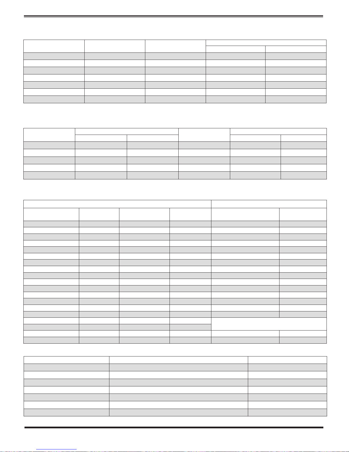
Repair Kits for 100-04/100-23 Hy-Check Main Valves
For: Hy-Check Main Valves—150 Pressure Class Only
Includes: Diaphragm, Disc and O-Rings and full set of spare Spacer Washers.
Larger Sizes: Consult Factory.
Repair Kits for 100-02/100-21 Powertrol and 100-03/100-22 Powercheck Main Valves
For: Powertrol and Powercheck Main Valves—150 Pressure Class Only
Includes: Diaphragm, Disc (or Disc Assembly) and O-rings and full set of spare Spacer Washers.
Repair Kits for Pilot Control Valves (In Standard Materials Only)
Includes: Diaphragm, Disc (or Disc Assembly), O-Rings, Gaskets or spare Screws as appropriate.
Repair Assemblies (In Standard Materials Only)
CLA-VAL
Copyright Cla-Val 2018 Printed in USA Specifications subject to change without notice.
1701 Placentia Ave • Costa Mesa CA 92627 Phone: 949-722-4800 • Fax: 949-548-5441 • E-mail: info@cla-val.com • www.cla-val.com
©
N-RK (R-08/2018)
Valve
Size
Kit Stock Number
100-02
Valve
Size
Kit Stock Number
100-02 & 100-03 100-21 & 100-22
3
⁄8”
9169901H
2
1
⁄2”
9169910J N/A
1
⁄2” & 3⁄4”
9169902F
3”
9169911G 9169905J
1” 9169903D
4”
9169912E 9169911G
1
1
⁄4” & 11⁄2”
9169904B
6”
9169913C 9169912E
2” 9169905J
8”
99116G 9169913C
10”
9169939H 99116G
12”
9169937B 9169939H
Valve
Size
Kit Stock Number
Valve
Size
Kit Stock Number
100-04 100-23 100-04 100-23
4” 20210901B N/A 12” 20210905H 20210904J
6” 20210902A 20210901B 14” 20210906G N/A
8” 20210903K 20210902A 16” 20210907F 20210905H
10” 20210904J 20210903K 20” N/A 20210907F
24” N/A 20210907F
BUNA-N
®
(Standard Material) VITON (For KB Controls)
Pilot
Control
Kit Stock
Number
Pilot
Control
Kit Stock
Number
Pilot
Control
Kit Stock
Number
CDB 9170006C CFM-9 12223E CDB-KB 9170012A
CDB-30 9170023H
CRA (w/bucking spring)
9170001D CRA-KB N/A
CDB-31 9170024F
CRD (w/bucking spring)
9170002B
CRD-KB (w/bucking spring)
9170008J
CDB-7 9170017K
CRD (no bucking spring)
9170003K CRL-KB 9170013J
CDH-2 18225D CRD-18 20275401K CDHS-2BKB 9170010E
CDHS-2 44607A CRD-22 98923G CDHS-2FKB 9170011C
CDHS-2B 9170004H CRL (55F, 55L) 9170007A CDHS-18KB (no bucking spring) 9170009G
CDHS-2F 9170005E CRL60/55L-60 9170033G
102C-KB
1726202D
CDHS-3C-A2 24657K CRL60/55L60 1" 9170042H
CDHS-8A 2666901A CRL-4A 43413E
CDHS-18 9170003K CRL-5 (55B) 65755B
CDS-4 9170014G CRL-5A (55G) 20666E
CDS-5 14200A CRL-18 20309801C
CDS-6 20119301A Universal CRL 9170041K
CDS-6A 20349401C CV 9170019F
CFCM-M1 1222301C X105L (O-ring) 00951E
Buna-N
®
CFM-2 12223E 102B-1 1502201F
CFM-7 1263901K 102C-2 1726201F CRD Disc Ret. (Solid) C5256H
CFM-7A 1263901K 102C-3 1726201F CRD Disc Ret. (Spring) C5255K
Control Description Stock Number
CF1-C1 Pilot Assembly Only 89541H
CF1-Cl Complete Float Control less Ball and Rod 89016A
CFC2-C1 Disc, Distributor and Seals 2674701E
CSM 11-A2-2 Mechanical Parts Assembly 97544B
CSM 11-A2-2 Pilot Assembly Only 18053K
33A 1” Complete Internal Assembly and Seal 2036030B
33A 2” Complete Internal Assembly and Seal 2040830J
When ordering, please give complete nameplate data of the valve and/or control being repaired. MINIMUM ORDER CHARGE APPLIES
Larger Sizes: Consult Factory.
 Loading...