CITIZEN RS-672, RS-670, RS-671 Datasheet

RS-670 NEW
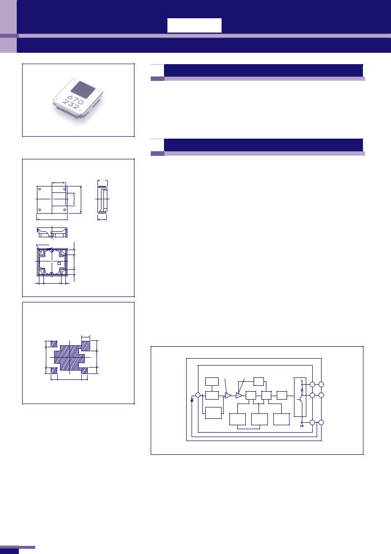
Micro-size Surface Mountable Infrared Remote Control Receiver Unit RS-670 Series


 Features
1.RS-670 4.5 (L)×5.0( )×1.35(H)mm
1.The RS-670 series are super-miniature chips with external dimensions 4.5(L)× 5.0(W)×1.35(H)mm.
2.Surface-mountable chips allow reflow mounting.
■ /Outline drawing
RS-670 /RS-670Series
|
2.2 |
1.35 /Case |
|
|
|
OUT |
GND |
|
|
|
|
0 7 6 5 X 4 |
2.45 |
4.5 |
Vcc |
GND |
1.32 |
5.0 |
4-R0.55 |
|
0.85 |
|
|
|
|
|
2.5 |
|
|
0.85 |
0.85 |
3.0 |
0.85 |
/Unit : mm
The following soldering patterns are recommended for
reflow-soldering:
|
|
2.2 |
1.6 |
|
2.0 |
2.5 |
|
2.1 |
1.6 |
|
1.6 |
1.6 |
3.0 |
1.6 |
(RS)
(Note)Remote control receiver unit (RS) should be
grounded wholly on its bottom side.


 Application
TV VTR TV, VCR, audio equipment, air conditioner,
|
automotive equipment, camera etc. |
|
■ /Absolute Maximum Rating |
|
|
|
|
(Ta 25 ) |
||||||
|
|
|
|
|
|
|
|
|
|
||
/Item |
|
|
|
/Symbol |
/Rating |
|
/Unit |
||||
/Power supply voltage |
|
|
V |
|
6 |
|
V |
||||
/Operating temperature range |
|
TOP |
|
-30 +85 |
|
|
|||||
/Storage temperature range |
|
TST |
|
-40 +90 |
|
|
|||||
■ /Recommended Operating Conditions |
|
|
|
||||||||
|
|
|
|
|
|
|
|
|
|||
|
|
|
|
|
|
|
|
|
|||
Item |
|
|
Symbol |
|
Recommended Operating Voltage |
|
Unit |
||||
/Power voltage |
|
VCC |
|
|
4.5 5.5 |
|
V |
||||
■ /Specifications |
|
|
|
|
|
|
|
|
|
||
|
|
|
|
|
|
|
|
|
|
|
|
|
|
/Carrier frequency |
/Specifications |
||||||||
|
|
|
|
|
|
|
|
||||
Series |
Feature |
40KHz |
|
38KHz |
36.7KHz |
||||||
|
Size of photo-diode |
Reaching distance |
|||||||||
RS-670 |
|
|
|
|
|
|
|
|
|
5m |
|
For general |
RS-670 |
|
RS-671 |
RS-672 |
□2mm |
||||||
RS-670 Series |
purpose |
|
|
|
|
|
|
|
|
5 meters min. |
|
|
|
|
|
|
|
|
|
|
|
||
|
|
|
|
|
|
|
|
|
|
|
|
■ /Internal circuit diagram |
|
|
|
||||
|
|
|
|
|
|
||
|
First stage |
Limiter |
|
Wave form shaping |
|||
|
amplifier |
|
amplifier |
|
circuit |
|
|
|
ABLC |
|
|
|
AGC |
|
Vcc |
|
|
|
|
|
|
|
1 |
|
|
|
|
|
|
22kΩ |
|
4 |
IN |
|
|
TRAP |
BPF |
Detector |
2 |
|
|
|
|
|
|
|
OUT |
|
|
|
|
|
|
|
|
|
Carier |
|
|
|
|
|
|
|
elimination |
TRAP |
Trimming |
|
|
||
|
|
fo setting |
GND |
||||
|
|
Skip |
|
|
circuit |
||
|
|
|
|
|
3 |
||
|
|
|
|
|
|
|
|
 90
90
 Loading...