


 Loading...
Cisco Wide Area Virtualization Engine 594 and 694 Hardware Installation Guide
May 24, 2013
Cisco Systems, Inc.
www.cisco.com
Cisco has more than 200 offices worldwide. Addresses, phone numbers, and fax numbers are listed on the Cisco website at www.cisco.com/go/offices.
Text Part Number: OL-24619-02
THE SPECIFICATIONS AND INFORMATION REGARDING THE PRODUCTS IN THIS MANUAL ARE SUBJECT TO CHANGE WITHOUT NOTICE. ALL STATEMENTS, INFORMATION, AND RECOMMENDATIONS IN THIS MANUAL ARE BELIEVED TO BE ACCURATE BUT ARE PRESENTED WITHOUT WARRANTY OF ANY KIND, EXPRESS OR IMPLIED. USERS MUST TAKE FULL RESPONSIBILITY FOR THEIR APPLICATION OF ANY PRODUCTS.
THE SOFTWARE LICENSE AND LIMITED WARRANTY FOR THE ACCOMPANYING PRODUCT ARE SET FORTH IN THE INFORMATION PACKET THAT SHIPPED WITH THE PRODUCT AND ARE INCORPORATED HEREIN BY THIS REFERENCE. IF YOU ARE UNABLE TO LOCATE THE SOFTWARE LICENSE OR LIMITED WARRANTY, CONTACT YOUR CISCO REPRESENTATIVE FOR A COPY.
The following information is for FCC compliance of Class A devices: This equipment has been tested and found to comply with the limits for a Class A digital device, pursuant to part 15 of the FCC rules. These limits are designed to provide reasonable protection against harmful interference when the equipment is operated in a commercial environment. This equipment generates, uses, and can radiate radio-frequency energy and, if not installed and used in accordance with the instruction manual, may cause harmful interference to radio communications. Operation of this equipment in a residential area is likely to cause harmful interference, in which case users will be required to correct the interference at their own expense.
The following information is for FCC compliance of Class B devices: The equipment described in this manual generates and may radiate radio-frequency energy. If it is not installed in accordance with Cisco’s installation instructions, it may cause interference with radio and television reception. This equipment has been tested and found to comply with the limits for a Class B digital device in accordance with the specifications in part 15 of the FCC rules. These specifications are designed to provide reasonable protection against such interference in a residential installation. However, there is no guarantee that interference will not occur in a particular installation.
Modifying the equipment without Cisco’s written authorization may result in the equipment no longer complying with FCC requirements for Class A or Class B digital devices. In that event, your right to use the equipment may be limited by FCC regulations, and you may be required to correct any interference to radio or television communications at your own expense.
You can determine whether your equipment is causing interference by turning it off. If the interference stops, it was probably caused by the Cisco equipment or one of its peripheral devices. If the equipment causes interference to radio or television reception, try to correct the interference by using one or more of the following measures:
•Turn the television or radio antenna until the interference stops.
•Move the equipment to one side or the other of the television or radio.
•Move the equipment farther away from the television or radio.
•Plug the equipment into an outlet that is on a different circuit from the television or radio. (That is, make certain the equipment and the television or radio are on circuits controlled by different circuit breakers or fuses.)
Modifications to this product not authorized by Cisco Systems, Inc. could void the FCC approval and negate your authority to operate the product.
The Cisco implementation of TCP header compression is an adaptation of a program developed by the University of California, Berkeley (UCB) as part of UCB’s public domain version of the UNIX operating system. All rights reserved. Copyright © 1981, Regents of the University of California.
NOTWITHSTANDING ANY OTHER WARRANTY HEREIN, ALL DOCUMENT FILES AND SOFTWARE OF THESE SUPPLIERS ARE PROVIDED “AS IS” WITH ALL FAULTS. CISCO AND THE ABOVE-NAMED SUPPLIERS DISCLAIM ALL WARRANTIES, EXPRESSED OR IMPLIED, INCLUDING, WITHOUT LIMITATION, THOSE OF MERCHANTABILITY, FITNESS FOR A PARTICULAR PURPOSE AND NONINFRINGEMENT OR ARISING FROM A COURSE OF DEALING, USAGE, OR TRADE PRACTICE.
IN NO EVENT SHALL CISCO OR ITS SUPPLIERS BE LIABLE FOR ANY INDIRECT, SPECIAL, CONSEQUENTIAL, OR INCIDENTAL DAMAGES, INCLUDING, WITHOUT LIMITATION, LOST PROFITS OR LOSS OR DAMAGE TO DATA ARISING OUT OF THE USE OR INABILITY TO USE THIS MANUAL, EVEN IF CISCO OR ITS SUPPLIERS HAVE BEEN ADVISED OF THE POSSIBILITY OF SUCH DAMAGES.
Cisco and the Cisco logo are trademarks or registered trademarks of Cisco and/or its affiliates in the U.S. and other countries. To view a list of Cisco trademarks, go to this URL: www.cisco.com/go/trademarks. Third-party trademarks mentioned are the property of their respective owners. The use of the word partner does not imply a partnership relationship between Cisco and any other company. (1110R)
Any Internet Protocol (IP) addresses used in this document are not intended to be actual addresses. Any examples, command display output, and figures included in the document are shown for illustrative purposes only. Any use of actual IP addresses in illustrative content is unintentional and coincidental.
Cisco Wide Area Virtualization Engine 594 and 694 Hardware Installation Guide
© 2013 Cisco Systems, Inc. All rights reserved.

|
|
|
|
|
|
|
|
|
C O N T E N T S |
|
|
Preface vii |
|
|
|
|
|
|
|
|
|
Introducing the Cisco Wide Area Virtualization Engine 594 and 694 1-1 |
|||||||
C H A P T E R |
1 |
||||||||
|
|
Supported Products |
1-1 |
|
|
|
|
|
|
|
|
Hardware Features |
1-1 |
|
|
|
|
|
|
|
|
Front Panel Components and LEDs |
1-2 |
|
|
||||
|
|
Back Panel Components and LEDs |
1-4 |
|
|
||||
|
|
Location of Ports and Connectors |
|
1-5 |
|
|
|||
|
|
Connecting a Console Terminal |
1-6 |
|
|
|
|
||
|
|
Cabling |
1-6 |
|
|
|
|
|
|
|
|
Installing the Cisco USB Driver |
1-6 |
|
|
||||
|
|
Preparing to Install the WAVE-594 and WAVE-694 2-1 |
|||||||
C H A P T E R |
2 |
||||||||
|
|
Safety Warnings and Cautions |
2-1 |
|
|
|
|
||
|
|
Safety Guidelines |
2-2 |
|
|
|
|
|
|
|
|
General Precautions 2-4 |
|
|
|
|
|
||
|
|
System Reliability Considerations |
|
2-5 |
|
|
|||
|
|
Protecting Against Electrostatic Discharge |
2-5 |
||||||
|
|
Understanding the Environmental Requirements |
2-5 |
||||||
|
|
Understanding the Power Requirements |
2-6 |
|
|||||
|
|
Understanding the Grounding Requirements |
2-6 |
|
|||||
|
|
Installing the WAVE-594 and WAVE-694 |
|
|
|
||||
C H A P T E R |
3 |
3-1 |
|
|
|||||
|
|
Rack-Mounting Considerations, Parts, and Tools |
3-1 |
||||||
|
|
Rack Mounting and Cabling the WAVE-594 and WAVE-694 3-2 |
|||||||
|
|
Mounting in a 4-Post Rack |
3-3 |
|
|
|
|
||
|
|
Front-Mounting in a 2-Post Rack |
3-5 |
|
|
||||
|
|
Cabling |
3-7 |
|
|
|
|
|
|
|
|
Connecting Power and Booting the System |
3-8 |
|
|||||
|
|
Checking the LEDs |
3-8 |
|
|
|
|
|
|
|
|
Removing or Replacing a WAVE Appliance |
3-9 |
|
|||||
Cisco Wide Area Virtualization Engine 594 and 694 Hardware Installation Guide
|
OL-24619-02 |
iii |
|

Contents
C H A P T E R |
4 |
Installing Hardware Options for the WAVE-594 and WAVE-694 4-1 |
|||||||
|
|
Installing a Cisco WAVE Interface Module |
4-1 |
|
|||||
|
|
Replacing a Hard Disk Drive/Solid State Drive |
4-2 |
||||||
|
|
Replacing a Fan |
4-4 |
|
|
|
|
|
|
|
|
Replacing a Power Supply |
4-5 |
|
|
|
|
||
|
|
Installing Memory |
4-6 |
|
|
|
|
|
|
|
|
Removing the Cover |
4-6 |
|
|
|
|
||
|
|
Installing Memory Modules |
4-7 |
|
|
||||
|
|
WAVE Interface Modules |
|
|
|
|
|
||
C H A P T E R |
5 |
5-1 |
|
|
|
|
|||
|
|
Interface Module Descriptions |
5-1 |
|
|
|
|||
|
|
Gigabit Ethernet Interface Module—Copper |
5-1 |
||||||
|
|
Gigabit Ethernet Interface Module—Fiber Optic 5-2 |
|||||||
|
|
10 Gigabit Ethernet Interface Module—Fiber Optic SFP+ 5-3 |
|||||||
|
|
Inline Interface |
5-4 |
|
|
|
|
|
|
|
|
Ports and LED Indicators |
5-5 |
|
|
|
|
||
|
|
Network Adapter Cabling Requirements |
5-8 |
|
|||||
|
|
Gigabit Ethernet—Copper |
5-8 |
|
|
|
|||
|
|
Gigabit Ethernet—Fiber Optic |
5-10 |
|
|
||||
|
|
Installation Scenarios and Cabling Examples for Fast Ethernet Connections 5-10 |
|||||||
|
|
Troubleshooting the System Hardware 6-1 |
|
||||||
C H A P T E R |
6 |
|
|||||||
|
|
Identifying System Problems 6-1 |
|
|
|
||||
|
|
Checking Connections and Switches |
6-2 |
|
|
||||
|
|
Troubleshooting the Ethernet Controller |
6-2 |
|
|||||
|
|
Network Connection Problems |
6-3 |
|
|
||||
|
|
Ethernet Controller Troubleshooting Chart |
6-3 |
||||||
|
|
Undetermined Problems |
6-4 |
|
|
|
|
||
|
|
Problem-Solving Tips |
6-5 |
|
|
|
|
||
|
|
Error Symptoms |
6-6 |
|
|
|
|
|
|
A P P E N D I X |
A |
WAVE-594 and WAVE-694 Hardware Specifications A-1 |
||||
|
|
|
|
Appliance Specifications A-1 |
|
|
|
|
|
|
Interface Module Specifications |
A-3 |
|
|
|
Maintaining the WAVE-594 and WAVE-694 B-1 |
||||
A P P E N D I X |
B |
|||||
|
|
|
|
Maintaining Your Site Environment |
B-1 |
|
|
|
|
Cisco Wide Area Virtualization Engine 594 and 694 Hardware Installation Guide |
|||
|
|
|
||||
|
|
|
|
|
|
|
|
iv |
|
|
|
OL-24619-02 |
|
|
|
|
|
|
||

Contents
Temperature B-2 |
|
|
|
|
Humidity |
B-2 |
|
|
|
Altitude B-2 |
|
|
|
|
Dust and Particles |
B-3 |
|
||
Corrosion |
B-3 |
|
|
|
Electrostatic Discharge |
B-3 |
|
||
Electromagnetic and Radio Frequency Interference B-4 |
||||
Magnetism |
B-4 |
|
|
|
Shock and Vibration |
B-4 |
|
||
Power Source Interruptions |
B-5 |
|||
Using Power Protection Devices |
B-5 |
|||
Surge Protectors |
B-6 |
|
|
|
Line Conditioners |
B-6 |
|
||
Uninterruptible Power Supplies B-6
I N D E X
Cisco Wide Area Virtualization Engine 594 and 694 Hardware Installation Guide
|
OL-24619-02 |
v |
|

Contents
Cisco Wide Area Virtualization Engine 594 and 694 Hardware Installation Guide
|
vi |
OL-24619-02 |
|
|
|

Preface
This preface describes the purpose of the Cisco Wide Area Virtualization Engine 594 and 694 Hardware Installation Guide, who should read it, how it is organized, and its document conventions.
This preface contains the following sections:
•Purpose, page vii
•Audience, page vii
•Organization, page viii
•Conventions, page viii
•Related Documentation, page xiii
•Obtaining Documentation and Submitting a Service Request, page xiv
Purpose
This installation guide explains how to prepare your site for installation, how to install a Wide Area Virtualization Engine 594 and 694 (WAVE-594 and WAVE-694) in an equipment rack, and how to maintain and troubleshoot the system hardware. After completing the hardware installation procedures covered in this guide, you will then use the appropriate related publications to configure your system. (See the “Related Documentation” section on page xiii.)
Audience
To use this installation guide, you should be familiar with internetworking equipment and cabling, and have a basic knowledge of electronic circuitry and wiring practices.
To complete the installation, including the software configuration for your WAVE-594 and WAVE-694 appliance and for the router that works with the WAVE-594 and WAVE-694 appliance, you should be familiar with basic networking principles, router configuration, and web page protocols.
Warning Only trained and qualified personnel should be allowed to install, replace, or service this equipment.
Statement 1030
Cisco Wide Area Virtualization Engine 594 and 694 Hardware Installation Guide
|
OL-24619-02 |
vii |
|

Organization
This guide is organized as follows:
Chapter |
Title |
Description |
|
|
|
Chapter 1 |
Introducing the Cisco Wide Area |
Describes the physical properties and provides a |
|
Virtualization Engine 594 and |
functional overview of the WAVE-594 and |
|
694 |
WAVE-694. |
|
|
|
Chapter 2 |
Preparing to Install the |
Describes safety considerations and gives an |
|
WAVE-594 and WAVE-694 |
overview of the installation and procedures that you |
|
|
should perform before the actual installation. |
|
|
|
Chapter 3 |
Installing the WAVE-594 and |
Describes how to install the hardware and connect |
|
WAVE-694 |
the external network interface cables. |
|
|
|
Chapter 4 |
Installing Hardware Options for |
Describes how to install Cisco Interface Modules, |
|
the WAVE-594 and WAVE-694 |
hard disk drives, fans, power supplies, and memory. |
|
|
|
Chapter 5 |
WAVE Interface Modules |
Describes the features and cabling requirements of |
|
|
the Cisco WAVE-594 and WAVE-694 Cisco |
|
|
Interface Modules. |
|
|
|
Chapter 6 |
Troubleshooting the System |
Describes troubleshooting procedures for the |
|
Hardware |
hardware installation. |
|
|
|
Appendix A |
WAVE-594 and WAVE-694 |
Gives a summary of the hardware features and |
|
Hardware Specifications |
specifications. |
|
|
|
Appendix B |
Maintaining the WAVE-594 and |
Describes how to maintain the WAVE-594 and |
|
WAVE-694 |
WAVE-694. |
|
|
|
Conventions
Command descriptions use the following conventions:
Convention |
Description |
|
|
boldface font |
Commands and keywords are in boldface. |
|
|
italic font |
Variables for which you supply values are in italics. |
|
|
[ ] |
Elements in square brackets are optional. |
|
|
{x | y | z} |
Alternative keywords are grouped in braces and separated |
|
by vertical bars. |
|
|
[x | y | z] |
Optional alternative keywords are grouped in brackets and |
|
separated by vertical bars. |
|
|
string |
A nonquoted set of characters. Do not use quotation marks |
|
around the string, or the string will include the |
|
quotation marks. |
|
|
Cisco Wide Area Virtualization Engine 594 and 694 Hardware Installation Guide
|
viii |
OL-24619-02 |
|
|
|

Screen examples use the following conventions:
Convention |
Description |
|
|
|
|
screen font |
Terminal sessions and information the system displays are |
|
|
|
in screen font. |
|
|
|
boldface screen |
Information you must enter is in boldface screen font. |
|
font |
|
|
|
|
|
italic screen |
Variables for which you supply values are in italic screen |
|
font |
font. |
|
|
|
|
^ |
|
The symbol ^ represents the key labeled Control—for |
|
|
example, the key combination ^D in a screen display means |
|
|
hold down the Control key while you press the D key. |
|
|
|
< |
> |
Nonprinting characters, such as passwords, are in angle |
|
|
brackets. |
|
|
|
[ |
] |
Default responses to system prompts are in square brackets. |
|
|
|
!, # |
An exclamation point (!) or a pound sign (#) at the |
|
|
|
beginning of a line of code indicates a comment line. |
|
|
|
Notes, cautionary statements, and safety warnings use these conventions:
Note Means reader take note. Notes contain helpful suggestions or references to materials not contained in this manual.
Caution Means reader be careful. You are capable of doing something that might result in equipment damage or loss of data.
Cisco Wide Area Virtualization Engine 594 and 694 Hardware Installation Guide
|
OL-24619-02 |
ix |
|

Warning IMPORTANT SAFETY INSTRUCTIONS
This warning symbol means danger. You are in a situation that could cause bodily injury. Before you work on any equipment, be aware of the hazards involved with electrical circuitry and be familiar with standard practices for preventing accidents. Use the statement number provided at the end of each warning to locate its translation in the translated safety warnings that accompanied this device. Statement 1071
SAVE THESE INSTRUCTIONS
Cisco Wide Area Virtualization Engine 594 and 694 Hardware Installation Guide
|
x |
OL-24619-02 |
|
|
|
Cisco Wide Area Virtualization Engine 594 and 694 Hardware Installation Guide
|
OL-24619-02 |
xi |
|

Cisco Wide Area Virtualization Engine 594 and 694 Hardware Installation Guide
|
xii |
OL-24619-02 |
|
|
|
Related Documentation
The WAVE-594 and WAVE-694 appliance supports the Cisco Wide Area Application Services software (WAAS) and can function as either a WAAS Central Manager or as an Application Acceleration Engine.
The Cisco WAAS software document set includes the following documents:
•Release Note for Cisco Wide Area Application Services
•Cisco Wide Area Application Services Upgrade Guide
•Cisco Wide Area Application Services Quick Configuration Guide
•Cisco Wide Area Application Services Configuration Guide
•Cisco Wide Area Application Services Command Reference
•Cisco Wide Area Application Services API Reference
•Cisco Wide Area Application Services Monitoring Guide
•Cisco WAAS Installation and Configuration Guide for Windows on a Virtual Blade
•Cisco WAAS Troubleshooting Guide for Release 4.1.3 and Later
Cisco Wide Area Virtualization Engine 594 and 694 Hardware Installation Guide
|
OL-24619-02 |
xiii |
|

The documentation for this product also includes the following hardware-related document:
• Regulatory Compliance and Safety Information for the Cisco Wide Area Virtualization Engines
Obtaining Documentation and Submitting a Service Request
For information on obtaining documentation, submitting a service request, and gathering additional information, see the monthly What’s New in Cisco Product Documentation, which also lists all new and revised Cisco technical documentation, at:
http://www.cisco.com/en/US/docs/general/whatsnew/whatsnew.html
Subscribe to the What’s New in Cisco Product Documentation as a Really Simple Syndication (RSS) feed and set content to be delivered directly to your desktop using a reader application. The RSS feeds are a free service and Cisco currently supports RSS version 2.0.
Cisco Wide Area Virtualization Engine 594 and 694 Hardware Installation Guide
|
xiv |
OL-24619-02 |
|
|
|

C H A P T E R 1
Introducing the Cisco Wide Area Virtualization
Engine 594 and 694
This chapter provides a basic functional overview of the Cisco Wide Area Virtualization Engine 594 and 694 (WAVE-594 and WAVE-694) appliance and describes the hardware, major components, and front and back panel indicators and controls.
This chapter contains the following sections:
•Supported Products, page 1-1
•Hardware Features, page 1-1
•Connecting a Console Terminal, page 1-6
Supported Products
The WAVE-594 and WAVE-694 appliance supports Cisco Wide Area Application Services (WAAS) software version 4.4.1 and later releases.
Hardware Features
This section illustrates and describes the front and back panel controls, ports, and LED indicators on the WAVE-594 and WAVE-694. It contains the following topics:
•Front Panel Components and LEDs, page 1-2
•Back Panel Components and LEDs, page 1-4
•Location of Ports and Connectors, page 1-5
Cisco Wide Area Virtualization Engine 594 and 694 Hardware Installation Guide
|
OL-24619-02 |
1-1 |
|
|
|
Chapter 1 Introducing the Cisco Wide Area Virtualization Engine 594 and 694
Hardware Features
Front Panel Components and LEDs
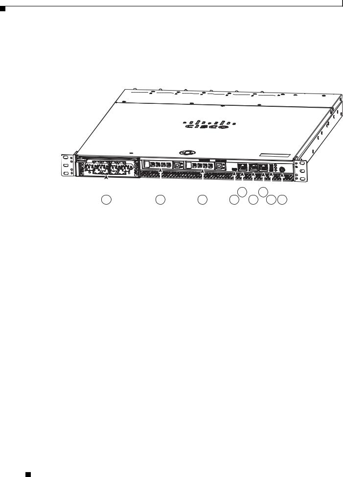
Figure 1-1 shows the front panel components.
Figure 1-1 |
Front Panel |
246569
Cisco Wide Area Virtualization Engine 594 
|
|
|
|
|
|
|
|
|
|
|
|
|
|
|
|
|
|
|
|
|
|
|
|
|
|
|
|
|
|
|
|
|
|
|
|
|
|
|
|
|
|
|
|
|
5 |
|
7 |
|
|
|
|
||
|
1 |
2 |
|
3 |
4 |
|
6 |
|
8 |
9 |
|||||||
|
|
|
|
|
|
|
|
|
|
|
|
|
|
|
|
||
1 |
Interface Module slot |
|
|
6 |
10/100/1000 GE 0/0 connector |
|
|
|
|
||||||||
|
|
|
|
|
|
|
|
|
|
|
|
|
|
|
|||
2 |
Hard drive bay 1 (device number |
7 |
10/100/1000 GE 0/1 connector |
|
|
|
|
||||||||||
|
0) |
|
|
|
|
|
|
|
|
|
|
|
|
|
|
|
|
|
|
|
|
|
|
|
|
|
|
|
|
|
|
|
|
||
3 |
Hard drive bay 2 (device number |
8 |
External USB port |
|
|
|
|
|
|
|
|||||||
|
1) |
|
|
|
|
|
|
|
|
|
|
|
|
|
|
|
|
|
|
|
|
|
|
|
|
|
|
|
|
|
|
|
|
|
|
4 |
Console port (mini-USB) |
|
|
9 |
Power On button |
|
|
|
|
|
|
|
|
|
|
||
|
|
|
|
|
|
|
|
|
|
|
|
|
|
|
|
|
|
5 |
Console port (RJ-45) |
|
|
|
|
|
|
|
|
|
|
|
|
|
|
|
|
|
|
|
|
|
|
|
|
|
|
|
|
|
|
|
|
|
|
Cisco Wide Area Virtualization Engine 594 and 694 Hardware Installation Guide
1-2 |
OL-24619-02 |
|
|
Chapter 1 Introducing the Cisco Wide Area Virtualization Engine 594 and 694
Hardware Features
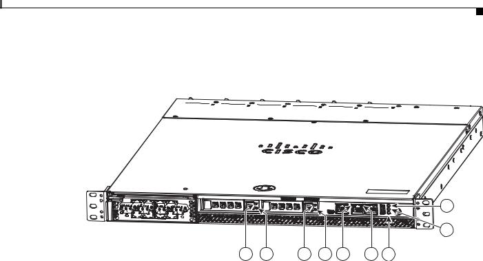
Figure 1-2 shows the front panel LEDs.
Figure 1-2 Front Panel LEDs
Cisco Wide Area Virtualization Engine 594 
1 |
2 |
3 |
4 |
5 |
6 |
9 |
Table 1-1 describes the front panel LEDs and their functions.
246570
7
8
|
|
Table 1-1 |
Front Panel LEDs |
|
|
|
|
|
||
|
|
|
|
|
|
|
|
|||
|
|
LED |
|
|
Color |
State |
Description |
|||
|
|
|
|
|
|
|||||
1,3 |
Drive activity LED |
Green |
Blinking |
Drive activity is normal. |
||||||
|
|
|
|
|
|
|
|
|||
|
|
|
|
|
Green |
On |
Online. |
|||
|
|
|
|
|
|
|
|
|||
|
|
|
|
|
Green |
Blinking |
Drive locate. |
|||
|
|
|
|
|
|
1Hz |
|
|
|
|
|
|
|
|
|
|
|
|
|||
|
|
|
|
|
— |
Off |
No reading/writing, no activity. |
|||
|
|
|
|
|
|
|||||
5 |
NIC link/activity |
Green |
On |
Link exists. |
||||||
|
|
|
|
|
|
|
|
|||
|
|
|
|
|
Green |
Blinking |
Activity exists. |
|||
|
|
|
|
|
|
|
|
|||
|
|
|
|
|
— |
Off |
No link detected. |
|||
|
|
|
|
|
|
|||||
6 |
NIC speed |
— |
Off |
10Mbps connection. |
||||||
|
|
|
|
|
|
|
|
|||
|
|
|
|
|
Green |
On |
100Mbps connection. |
|||
|
|
|
|
|
|
|
|
|||
|
|
|
|
|
Yellow |
On |
1000Mbps connection. |
|||
|
|
|
|
|
|
|||||
7 |
System power LED |
Green |
On |
System is on. |
||||||
|
|
|
|
|
|
|
|
|||
|
|
|
|
|
— |
Off |
Power cord is not attached or power supply |
|||
|
|
|
|
|
|
|
failure has occurred. |
|||
|
|
|
|
|
|
|||||
8 |
System fault LED |
Yellow |
On |
System has detected a fault. Refer to the |
||||||
|
|
|
|
|
|
|
“Troubleshooting the System Hardware” |
|||
|
|
|
|
|
|
|
chapter for more information. |
|||
|
|
|
|
|
|
|
|
|||
|
|
|
|
|
— |
Off |
System operation is normal. |
|||
|
|
|
|
|
|
|||||
9 |
Storage activity LED |
Green |
Blinking |
Drive activity is normal. |
||||||
|
|
|
|
|
|
|
|
|||
|
|
|
|
|
Orange |
On |
Drive failure has occurred. |
|||
|
|
|
|
|
|
|
|
|
|
|
|
|
|
|
Cisco Wide Area Virtualization Engine 594 and 694 Hardware Installation Guide |
|
|
||||
|
|
|
|
|
||||||
|
|
|
|
|
|
|
|
|
|
|
|
OL-24619-02 |
|
|
|
|
|
|
1-3 |
|
|
|
|
|
|
|
|
|
|
|||

Chapter 1 Introducing the Cisco Wide Area Virtualization Engine 594 and 694
Hardware Features
Back Panel Components and LEDs
Figure 1-3 shows the back panel components.
Note To monitor the boot process in normal operation, use a console port.
Figure 1-3 Back Panel Components
|
1 |
2 |
3 |
|
4 |
5 |
6 |
7 |
8 |
|
|
|
|
|
|
|
|
|
|
1 |
Power supply 1 |
|
|
5 |
Fan 4 |
|
|
|
|
|
|
|
|
|
|
|
|
|
|
2 |
Power supply 0 |
|
|
6 |
Fan 3 |
|
|
|
|
|
|
|
|
|
|
|
|
|
|
3 |
Fan 6 |
|
|
7 |
Fan 2 |
|
|
|
|
|
|
|
|
|
|
|
|
|
|
4 |
Fan 5 |
|
|
8 |
Fan 1 |
|
|
|
|
|
|
|
|
|
|
|
|
|
|
Figure 1-4 shows the back panel LEDs.
Figure 1-4 |
Back Panel LEDs |
|
|
|
|
|
|
1 |
2 |
3 |
4 |
5 |
6 |
7 |
8 |
Table 1-2 describes the back panel LEDs and their functions.
Table 1-2 |
Back Panel LEDs |
|
|
||
|
|
|
|
|
|
LED |
|
|
Color |
State |
Description |
|
|
|
|
|
|
1, 2 |
Power supply status |
— |
Off |
No AC power to all power supplies. |
|
|
|
|
|
|
|
|
|
|
Red |
Blinking |
No AC power to this power supply. |
|
|
|
|
|
|
|
|
|
Green |
Blinking |
AC power is present, only standby output on. |
|
|
|
|
|
|
|
|
|
Green |
On |
Power supply DC outputs on and OK. |
|
|
|
|
|
|
|
|
|
Red |
On |
Power supply failure. Refer to the |
|
|
|
|
|
“Troubleshooting the System Hardware” |
|
|
|
|
|
chapter for more information. |
|
|
|
|
|
|
Cisco Wide Area Virtualization Engine 594 and 694 Hardware Installation Guide
1-4 |
OL-24619-02 |
|
|

Chapter 1 Introducing the Cisco Wide Area Virtualization Engine 594 and 694
Hardware Features
Table 1-2 |
Back Panel LEDs (continued) |
|
|||
|
|
|
|
|
|
LED |
|
|
Color |
State |
Description |
|
|
|
|
|
|
3 - 8 |
Fan status |
Orange |
On |
Alarm. |
|
|
|
|
|
|
|
|
|
|
Orange |
Blinking |
Alarm. Fan speed too low. |
|
|
|
|
|
|
|
|
|
— |
Off |
Normal state. |
|
|
|
|
|
|
Location of Ports and Connectors
The WAVE appliance supports two Ethernet connectors and two Console ports on the front of the appliance.
Figure 1-3 shows the back panel ports and connectors.
Warning To avoid electric shock, do not connect safety extra-low voltage (SELV) circuits to telephone-network voltage (TNV) circuits. LAN ports contain SELV circuits, and WAN ports contain TNV circuits. Some LAN and WAN ports both use RJ-45 connectors. Use caution when connecting cables. Statement 1021
This section contains the following topics:
•Ethernet Port Connectors
•Console Port Connector
Ethernet Port Connectors
Connect a Category 3, 4, or 5 unshielded twisted-pair cable to an Ethernet connector. 100BASE-TX and 1000BASE-T Fast Ethernet standards require Category 5 or higher cabling.
The WAVE-594 and WAVE-694 appliance has two Ethernet connectors that are attached to the Ethernet controllers (see Figure 1-5). The Ethernet controllers are integrated on the system board. They provide an interface for connecting to a 10-Mbps, 100-Mbps, or 1-Gbps network and provide full-duplex (FDX) capability, which enables simultaneous transmission and reception of data on the network. If the Ethernet ports in the server support auto negotiation, the controllers detect the data-transfer rate (10BASE-T, 100BASE-TX, or 1000BASE-T) and duplex mode (full duplex or half duplex) of the network and automatically operate at that rate and mode. You do not have to set any jumpers or configure the controllers.
Note There is a third RJ45 connector on the front of the appliance (see Figure 1-1). This is a console port. Do not connect this port to your network.
Cisco Wide Area Virtualization Engine 594 and 694 Hardware Installation Guide
|
OL-24619-02 |
1-5 |
|
|
|

Chapter 1 Introducing the Cisco Wide Area Virtualization Engine 594 and 694
Connecting a Console Terminal
Figure 1-5 Ethernet Port Connector
Link/Activity |
|
|
|
|
|
|
|
|
|
|
|
Speed LED |
|
|
|
|
|
|
|
|
|
|
|
||
|
|
|
|
|
|
|
|
|
|
|
||
LED |
|
|
|
|
|
|
|
|
|
|
|
|
|
|
|
|
|
|
|
|
|
|
|
|
330210 |
|
|
|
|
|
|
|
|
|
|
|
|
|
|
|
|
|
|
|
|
|
|
|
|
|
|
8 |
|
|
|
|
|
|
|
1 |
|
|
||
Console Port Connector
The WAVE-594 and WAVE-694 appliance has two console port connectors, serial and mini-USB (see Figure 1-1). Use a console port connector to access the command-line interface (CLI) for controlling the WAVE appliance.
For information on connecting a console terminal to the mini-USB console port, see the “Connecting a Console Terminal” section on page 1-6.
Connecting a Console Terminal
The WAVE appliance has both serial and mini-USB console ports (see Figure 1-1). These ports provide administrative access to your appliance with a console terminal or PC.
Note You cannot use both ports at the same time. If both ports are connected, the mini-USB port takes priority.
Note When using the mini-USB port to connect to a Windows-based PC for the first time, you must install the Windows USB driver on the PC first. See the “Installing the Cisco USB Driver” section on page 1-6.
Cabling
The following cables included with the WAVE appliance may be used for connecting the WAVE appliance to a console terminal or PC:
•USB Console cable—5-pin USB to mini-USB Type A-B
•Serial Console cable— EIA RJ-45 to DB-9
Installing the Cisco USB Driver
When using the mini-USB port to connect a Microsoft Windows based PC as a console terminal to the WAVE appliance, you must first install the Windows USB driver on the PC. Otherwise, the USB interface may not function.
The following Windows operating systems are supported:
• Windows XP—32-bit and 64-bit
Cisco Wide Area Virtualization Engine 594 and 694 Hardware Installation Guide
1-6 |
OL-24619-02 |
|
|
Chapter 1 Introducing the Cisco Wide Area Virtualization Engine 594 and 694
Connecting a Console Terminal
•Vista—32-bit, Business edition
•Vista—64-bit
•Windows 7—32-bit and 64-bit
To install the Cisco Microsoft Windows USB driver, perform the following steps:
Note Do not connect the cable from the Windows PC to the WAVE appliance until after the driver is installed.
Step 1 Load the DVD that came with your WAVE appliance and double-click the CUSBInst.exe file. The Cisco Virtual Com InstallShield Wizard begins.
You can also access the driver from the WAAS software download area of Cisco.com located at:
http://www.cisco.com/cisco/pub/software/portal/select.html?&mdfid=280484571&catid=268437639&
softwareid=280836712
It’s located under release 4.4.1 and the filename is CUSBInst_Signed_18May2011.exe
Step 2 Click Next. The Ready to Install the Program window appears.
Step 3 Click Install. The InstallShield Wizard Completed window appears.
Step 4 Click Finish.
Step 5 Connect the USB cable to the PC USB port and WAVE appliance mini-USB console port. Within a few moments, the Found New Hardware Wizard appears.
Follow the instructions to complete the installation of the driver.
Step 6 Once the installation is finished, the USB console is ready for use.
Note If the driver has been installed on the PC but does not get bound to the hardware, you can manually browse the driver installation query to the location C:\Windows\tiinst\. The newly attached hardware will appear in the Windows Device Manager as "TUSB3410 EECode Ser".
This solution also applies when connecting additional WAVE appliances to the same PC. Multiple WAVE appliances can be independently administered by console sessions on the same PC.
Note You do not need to reinstall the driver if you change to a different USB port on your PC.
Note If you happen to install the driver multiple times, each time the driver is installed the virtual COM port number assigned to the USB port gets incremented. This is expected behavior and may not get reset even if you uninstall the driver.
Cisco Wide Area Virtualization Engine 594 and 694 Hardware Installation Guide
|
OL-24619-02 |
1-7 |
|
|
|

Chapter 1 Introducing the Cisco Wide Area Virtualization Engine 594 and 694
Connecting a Console Terminal
Cisco Wide Area Virtualization Engine 594 and 694 Hardware Installation Guide
1-8 |
OL-24619-02 |
|
|

C H A P T E R 2
Preparing to Install the WAVE-594 and WAVE-694
This chapter contains important safety information that you should know before you work with the WAVE-594 and WAVE-694. Use the guidelines in this chapter to ensure your own personal safety and to help protect your appliance from potential damage.
This chapter contains the following sections:
•Safety Warnings and Cautions, page 2-1
•Safety Guidelines, page 2-2
•Understanding the Environmental Requirements, page 2-5
•Understanding the Power Requirements, page 2-6
•Understanding the Grounding Requirements, page 2-6
Note Read the Regulatory Compliance and Safety Information for Cisco Wide Area Virtualization Engines document and the Site Preparation and Safety Guide that came with your appliance before you begin the installation.
Safety Warnings and Cautions
Before you install the WAVE-594 and WAVE-694, observe the following safety warnings and cautions:
Warning Read the installation instructions before connecting the system to the power source. Statement 1004
Warning This unit is intended for installation in restricted access areas. A restricted access area can be accessed only through the use of a special tool, lock and key, or other means of security.
Statement 1017
Warning The plug-socket combination must be accessible at all times, because it serves as the main disconnecting device. Statement 1019
Cisco Wide Area Virtualization Engine 594 and 694 Hardware Installation Guide
|
OL-24619-02 |
2-1 |
|
|
|
Chapter 2 Preparing to Install the WAVE-594 and WAVE-694
Safety Guidelines
Warning
Warning
Warning
Warning
Warning
Caution
Caution
This equipment must be grounded. Never defeat the ground conductor or operate the equipment in the absence of a suitably installed ground conductor. Contact the appropriate electrical inspection authority or an electrician if you are uncertain that suitable grounding is available. Statement 1024
This unit might have more than one power supply connection. All connections must be removed to de-energize the unit. Statement 1028
Only trained and qualified personnel should be allowed to install, replace, or service this equipment.
Statement 1030
This product requires short-circuit (overcurrent) protection, to be provided as part of the building installation. Install only in accordance with national and local wiring regulations. Statement 1045
Installation of the equipment must comply with local and national electrical codes. Statement 1074
To properly ventilate the system, you must provide at least 7.6 cm (3.0 in) of clearance at the front and back of the WAVE appliance.
To reduce the risk of electric shock or damage to the equipment:
-Do not disable the power cord grounding plug. The grounding plug is an important safety feature.
-Plug the power cord into a grounded (earthed) electrical outlet that is easily accessible at all times.
-Unplug the power cord from the power supply to disconnect power to the equipment.
-Do not route the power cord where it can be walked on or pinched by items placed against it. Pay particular attention to the plug, electrical outlet, and the point where the cord extends from the WAVE appliance.
Caution To reduce the risk of personal injury or damage to the equipment:
-Observe local occupation health and safety requirements and guidelines for manual handling.
-Obtain adequate assistance to lift and stabilize the chassis during installation or removal. The WAVE appliance is unstable when not fastened to the rails. When mounting the WAVE appliance in a rack, remove the power supplies and any other removable module to reduce the overall weight of the product.
Safety Guidelines
To reduce the risk of bodily injury, electrical shock, fire, and damage to the equipment, observe the precautions in this section.
This section contains the following topics:
• General Precautions, page 2-4
Cisco Wide Area Virtualization Engine 594 and 694 Hardware Installation Guide
2-2 |
OL-24619-02 |
|
|

Chapter 2 Preparing to Install the WAVE-594 and WAVE-694
Safety Guidelines
•System Reliability Considerations, page 2-5
•Protecting Against Electrostatic Discharge, page 2-5
Cisco Wide Area Virtualization Engine 594 and 694 Hardware Installation Guide
|
OL-24619-02 |
2-3 |
|
|
|

Chapter 2 Preparing to Install the WAVE-594 and WAVE-694
Safety Guidelines
General Precautions
Observe the following general precautions for using and working with the WAVE-594 and WAVE-694:
•Observe and follow service markings. Do not service any Cisco product except as explained in your system documentation. Opening or removing covers that are marked with the triangular symbol with a lightning bolt may expose you to electrical shock. Components inside these compartments should be serviced only by a trained and qualified service technician.
•If any of the following conditions occur, unplug the product from the electrical outlet and replace the part or contact your customer service representative:
–The power cable or plug is damaged.
–An object has fallen into the product.
–The product has been exposed to water.
–The product has been dropped or damaged.
–The product does not operate correctly when you follow the operating instructions.
•Keep your system components away from radiators and heat sources. Also, do not block cooling vents.
•Do not spill food or liquids on your system components, and never operate the product in a wet environment.
•Do not push any objects into the openings of your system components. Doing so can cause fire or electric shock by shorting out interior components.
•Use the product only with other Cisco-approved equipment.
•Allow the product to cool before removing covers or touching internal components.
•Use the correct external power source. Operate the product only from the type of power source indicated on the electrical ratings label. If you are not sure of the type of power source required, consult your service representative or local power company.
•Use only approved power cables. If you have not been provided with a power cable for your WAVE appliance or for any AC-powered option intended for your system, purchase a power cable that is approved for use in your country. The power cable must be rated for the product and for the voltage and current marked on the product’s electrical ratings label. The voltage and current rating of the cable should be greater than the ratings marked on the product.
•To help prevent electric shock, plug the system components and peripheral power cables into properly grounded electrical outlets. These cables are equipped with three-prong plugs to help ensure proper grounding. Do not use adapter plugs or remove the grounding prong from a cable.
•Observe power strip ratings. Make sure that the total ampere rating of all products plugged into the power strip does not exceed 80 percent of the power strip ampere ratings limit.
•Do not use appliance or voltage converters or kits sold for appliances with your product.
•To help protect your system components from sudden, transient increases and decreases in electrical power, use a surge suppressor, line conditioner, or uninterruptible power supply (UPS).
•Position cables and power cords carefully; route cables and the power cord and plug so that they cannot be stepped on or tripped over. Be sure that nothing rests on your system components’ cables or power cord.
•Do not modify power cables or plugs. Consult a licensed electrician or your power company for site modifications. Always follow your local or national wiring rules.
Cisco Wide Area Virtualization Engine 594 and 694 Hardware Installation Guide
2-4 |
OL-24619-02 |
|
|
Loading...