


Topspin 270
Table of contents
 Loading...
Part Number: 10-00044-04-A0
Topspin 270/Cisco SFS 7008 Hardware Guide
Release 2.3.0

Copyright © 2004 - 2005 Topspin Communications, Inc. All rights reserved.
The Topspin Switched Computing System, Topspin Host Channel Adapter, Topspin Element Manager, and collateral
software programs and documentation are subject to and made available only pursuant to the license agreement
signed by you and Topspin, Communications, Inc. (or if no signed license agreement exists, the license agreement
included with your original media) and may only be used in accordance with the terms of that agreement. Making
copies, modifications, or compilation works of the software except as specifically allowed in that agreement is
prohibited by law and constitutes a punishable violation of the law. This documentation may not be copied, modified
or reduced to any electronic or machine-readable form without Topspin Communication, Inc.'s prior written consent.
As defined in FAR section 2.101, DFAR section 252.227-7014(a)(1) and DFAR section 252.227-7014(a)(5) or
otherwise, the collateral software programs provided to you are “commercial items,” “commercial computer
software” and/or “commercial computer software documentation.” Consistent with DFAR section 227.7202, FAR
section 12.212 and other sections, any use, modification, reproduction, release, performance, display, disclosure or
distribution thereof by or for the U.S. Government shall be governed solely by the terms of the license agreement and
shall be prohibited except to the extent expressly permitted by the terms of that agreement. Any technical data
provided that is not covered by the above provisions shall be deemed “technical data-commercial items” pursuant to
DFAR section 227.7015(a) or equivalent. Any use, modification, reproduction, release, performance, display or
disclosure of such technical data shall be governed by the terms of DFAR section 227.7015(b) or equivalent.
This documentation may include technical inaccuracies or typographical errors and is subject to correction and other
revision without notice. TOPSPIN PROVIDES THIS DOCUMENTATION “AS IS” AND WITHOUT ANY
WARRANTIES OF ANY KIND, EITHER EXPRESS OR IMPLIED, INCLUDING BUT NOT LIMITED TO THE
IMPLIED WARRANTIES OF MERCHANTABILITY OR FITNESS FOR A PARTICULAR PURPOSE. Some
states or jurisdictions do not allow disclaimer of express or implied warranties in certain transactions; therefore, this
statement may not apply to you.
© Copyright 2004 - 2005, Topspin Communications, Inc. All rights reserved. Topspin is a registered trademark and
the Topspin logo, TopspinOS, and Topspin Switched Computing System are trademarks of Topspin Communications,
Inc. Other company, product, or service names are the property of their respective owners.
Document Version: 2.3.0
Part Number: 10-00044-04-A0
June, 2005
Printed in the United States of America.

iii
Regulatory Notices........................................ vii
FCC Statement.......................................................................................................................................... vii
Safety Information .................................................................................................................................... vii
Electrical Cautions....................................................................................................................... vii
General Cautions........................................................................................................................... ix
Contact Information................................................................................................................................... ix
1: Features Overview ................................... 11
System Architecture...................................................................................................................................11
Hot Standby .................................................................................................................................. 11
InfiniBand Connectivity ............................................................................................................... 12
Flexibility...................................................................................................................................... 12
Hi-Availability .............................................................................................................................. 12
Non-Blocking Architecture........................................................................................................... 13
About the Topspin 270/Cisco SFS 7008 Chassis ......................................................................................13
Diagram of the Chassis ................................................................................................................. 13
Chassis Slot Numbering................................................................................................................ 15
Dimensions ................................................................................................................................... 16
Connections .................................................................................................................................. 16
LEDs ............................................................................................................................................. 16
Power Supplies ............................................................................................................................. 16
Fan Trays ...................................................................................................................................... 17
Management Interface Modules ................................................................................................... 17
Fabric Controller Modules............................................................................................................ 18
Node and Core Slots ..................................................................................................................... 18
Line Interface Modules (LIM)...................................................................................................... 19
Chassis ID Module........................................................................................................................ 19
Rack Alarm ................................................................................................................................... 19
Administrative Features.............................................................................................................................20
Real-Time Clock........................................................................................................................... 20
Latency.......................................................................................................................................... 20
Non-Volatile Memory................................................................................................................... 20
Vital Product Data Storage ........................................................................................................... 20
Diagnostics.................................................................................................................................... 20
2: Installing the Topspin 270/Cisco SFS 7008 21
Prepare the Site ..........................................................................................................................................21
Read the Cautionary Statements ................................................................................................... 21
Prepare the Physical Environment for the Topspin 270/Cisco SFS 7008 System........................ 21
Mount the Topspin 270/Cisco SFS 7008 Chassis in a Rack......................................................................22
Requirements ................................................................................................................................ 22
Rack Mount Installation................................................................................................................ 22
Install Optional HA Components ..............................................................................................................26

iv
Connect Management Devices ..................................................................................................................26
Attach a Serial Console Cable to a PC or Terminal ..................................................................... 26
Connect an Ethernet Cable to the Ethernet Management Port ..................................................... 27
Recommended Management Configuration ................................................................................. 27
Power on the Chassis .................................................................................................................... 28
Configure Basic Connectivity....................................................................................................................29
Assigning an Address Statically ................................................................................................... 29
Assigning an Address Dynamically.............................................................................................. 30
Connect Network Devices .........................................................................................................................30
About Connectors ......................................................................................................................... 30
Connecting InfiniBand Devices.................................................................................................... 31
Manage the System....................................................................................................................................32
(Optional) Launch the Chassis Manager ...................................................................................... 32
(Optional) Install the Element Manager GUI ............................................................................... 34
3: Managing Individual Components............ 35
About the Field Replaceable Units ............................................................................................................35
Power Supply Modules..............................................................................................................................35
About the Power Supply Modules ................................................................................................ 35
Removing a Power Supply Module .............................................................................................. 36
Installing a New Power Supply Module ....................................................................................... 38
Fan Tray Modules......................................................................................................................................39
About the Fan Tray Modules ........................................................................................................ 39
Removing a Fan Module............................................................................................................... 39
Installing a Fan Module ................................................................................................................ 41
Fabric Controllers ......................................................................................................................................42
About the Fabric Controllers ........................................................................................................ 42
Removing a Fabric Controller ...................................................................................................... 42
Installing a Fabric Controller........................................................................................................ 44
Upgrading the Controller Card ..................................................................................................... 44
Line Interface Management Modules (LIM) .............................................................................................45
About LIM Cards.......................................................................................................................... 45
Removing a LIM Card.................................................................................................................. 45
Installing a LIM Module............................................................................................................... 48
Management Interface Modules ................................................................................................................49
About Management Interface Modules ........................................................................................ 49
Removing a Management Interface Module................................................................................. 49
Installing a Management Interface Module .................................................................................. 50
Chassis ID Modules ...................................................................................................................................50
About Chassis ID Modules ........................................................................................................... 50
Removing a Chassis ID Module ................................................................................................... 50
Installing a Replacement Chassis ID Module............................................................................... 52
4: Administrative Tasks ................................ 53
Upgrade all Cards in a Chassis ..................................................................................................................53

v
Upgrading a Topspin 270/Cisco SFS 7008 with the CLI ............................................................. 53
Upgrading a Topspin 270/Cisco SFS 7008 with Element Manager............................................. 54
Upgrading an Individual Controller Card..................................................................................................56
Upgrading a Controller Card with the CLI................................................................................... 57
Upgrading Individual Node Cards.............................................................................................................59
Upgrading a Node Card with Element Manager........................................................................... 60
Upgrading a New Management I/O Card ..................................................................................................63
Upgrade a New Management I/O Card with the CLI................................................................... 63
Upgrade a New Management I/O Card with Element Manager................................................... 64
5: Monitoring the Topspin 270/Cisco SFS 7008
System ......................................................... 67
Interpreting the Front Panel LEDs.............................................................................................................67
System-Wide Status LED ............................................................................................................. 68
Power Supply LEDs...................................................................................................................... 69
Fan LEDs ...................................................................................................................................... 71
Fabric Controller LEDs ................................................................................................................ 72
Interpreting the Back Panel LEDs .............................................................................................................73
Management Interface Module LEDs........................................................................................... 73
Chassis ID LEDs........................................................................................................................... 76
LIM Status LEDs .......................................................................................................................... 77
InfiniBand Port LEDs ................................................................................................................... 77
Monitoring the System with Chassis Manager ..........................................................................................78
Monitor the Device ....................................................................................................................... 78
Monitor the Cards ......................................................................................................................... 81
Monitor the InfiniBand Ports........................................................................................................ 82
Monitor the Power Supplies ......................................................................................................... 83
Monitor the Fans........................................................................................................................... 84
Monitor the Temperature .............................................................................................................. 85
Monitoring the System with Element Manager.........................................................................................86
Interpreting the Summary Tab...................................................................................................... 86
Interpreting the Power Supplies Tab ............................................................................................ 87
Interpreting the Fans Tab.............................................................................................................. 87
Interpreting the Sensors Tab ......................................................................................................... 87
Monitor the System With the CLI .............................................................................................................88
6: Hardware Diagnostic Tests ...................... 91
About Diagnostic Tests..............................................................................................................................91
LED Tests ..................................................................................................................................... 91
Self Tests....................................................................................................................................... 91
Run Card Tests...........................................................................................................................................92
Run a Card Self-Test..................................................................................................................... 92
Run Chassis Tests ......................................................................................................................................94
Run a Chassis Standard Test......................................................................................................... 95

vi
Run Fan Tests ............................................................................................................................................96
Run a Self-Test on a Fan............................................................................................................... 96
Run Power Supply Tests............................................................................................................................98
Run a LED Test on the Power Supply.......................................................................................... 98
Run a Self-Test on a Power Supply .............................................................................................. 99
Displaying Hardware Errors ....................................................................................................................101
7: Specifications and Compliance Certifications
105
Chassis and Management Interface ............................................................................................ 105
Electrical Specifications ............................................................................................................. 106
EMC/Immunity........................................................................................................................... 106
Safety .......................................................................................................................................... 106
Acoustics..................................................................................................................................... 106
Product Markings........................................................................................................................ 107
8: Index ...................................................... 109

vii
Regulatory Notices
FCC Statement
This equipment has been tested and found to comply with the limits for a Class A digital device,
pursuant to Part 15 of the FCC Rules. These limits are designed to provide reasonable protection against
harmful interference when the equipment is operated in a commercial environment. This equipment
generates, uses, and can radiate radio frequency energy and, if not installed and used in accordance with
the instruction manual, may cause harmful interference to radio communications. Operation of this
equipment in a residential area is likely to cause harmful interference in which case the user will be
required to correct the interference at his own expense.
Safety Information
• “Electrical Cautions” on page vii
• “General Cautions” on page ix
Electrical Cautions
CAUTION: Use only the power cable provided with your Topspin system. Inspect the power cord and
determine if it provides the proper plug and is appropriately certified for use with your electrical system.
Discard the cord if it is inappropriate for your country’s electrical system and obtain the proper cord, as
required by your national electrical codes or ordinances.

viii
CAUTION: Grounding is supplied by the ground-prong on the 3-prong power cable. Do not attach a
separate ground cable. Do not use adapter plugs. Do not remove the ground prong from the cable.
Ensure the ground connection on the power supply is correct and functioning before applying power to
the Topspin system.
CAUTION: Always ground yourself before touching any internal Topspin system component to avoid
damage from electrostatic discharge (ESD).
CAUTION: The Topspin system has two power cables. The operator must disconnect all power cables
before attempting to remove the system from the rack.
CAUTION: Remove power cables by grasping the cable connector and pulling straight out.If the
chassis comes equipped with a power-plug retainer, move the bail wire used to retain the plug to the
side before attempting to remove the power plug. Replace power-supply cables be grasping the cable
connector, align the connector with the power jack, and insert the connector straight into the jack.If the
chassis comes equipped with a power-plug retainer, move the bail wire back into place to keep the
power plug firmly in place.
CAUTION: The Topspin system contains lithium batteries. Do not attempt to replace or discard these
batteries. The batteries may only be serviced by Topspin service personnel.
CAUTION: Observe and follow service markings. Do not service the Topspin system, except as
explained in the Topspin documentation supplied with your system. Opening the chassis or removing
the enclosure cover exposes you to electrical shock and may damage system components.
If one or more of the following situations occurs, remove power to the Topspin system chassis, and
contact your Topspin support representative:
• The power cable or power plug is damaged.
• The system has been exposed to water.
• The system has been dropped or damaged in any way.
• The system does not operate correctly after following the installation instructions.
CAUTION: You must ensure the operating environment has adequate air circulation. Keep the
Topspin system in a cool, well-ventilated room. Do not block cooling vents. Install filler panels into all
unused slots.

ix
CAUTION: Never place your hand inside an empty card or module bay. You should never have cause
to place a hand anywhere inside the Topspin chassis. Unused card and module bays should always have
a Topspin cover over the bay to ensure proper safety, ventilation, and cooling.
General Cautions
CAUTION: No user is authorized to remove the Topspin system enclosure cover. The internal chassis
contains no user-serviceable components. Removing the enclosure cover voids your warranty. See the
warranty card for further details regarding the servicing of your chassis.
In general
• Do not spill food or liquids on your system components.
• Protect your Topspin system from sudden power-surges and interruptions by using a surge
suppressor, line conditioner, or uninterruptable power supply (UPS).
• Place cables appropriately so that they do not obstruct any egress within the data center and they do
not block any ventilation inlets or outlets.
• Rack mount the Topspin chassis according to the rack manufacturer recommendations.
Contact Information
Table III-1: Customer Contact Information
Address Topspin Communications, Inc.
515 Ellis St.
Mountain View, CA 94043
Telephone, Corporate Headquarters (866) TOPSPIN or (650) 316-3300
Fax (650) 316-3269
Telephone, Technical Support (800) 499-1473
Email, Technical Support support@topspin.com
Web site, Support http://support.topspin.com

x

11
1
Features Overview
The Topspin 270/Cisco SFS 7008 Server Switch provides data center managers with a
high-performance, low-latency interconnect.
• “System Architecture” on page 11.
• “About the Topspin 270/Cisco SFS 7008 Chassis” on page 13.
• “Administrative Features” on page 20.
System Architecture
Hot Standby
On the Topspin 270/Cisco SFS 7008, the inactive controller card remains on hot standby so that it can
assume control in the event that the active controller card fails over. The hot standby feature lets the
Server Switch fail over without rebooting or resetting any cards in the chassis.
You can access the hot standby controller card with a connection to the serial console port. A CLI
session to the standby controller provides read-only access to the controller. You can view but not
configure the card.
Because the hot standby features keeps both controller cards up, the show card command identifies the
card on which your CLI session runs. In the command output, an asterisk identifies the controller card
to which you are connected. In the example that follows, the CLI session applies to the controller card
in slot 11 (the active card), as identified by the asterisk next to the slot number (line 10).

12
Example
The oper code field of the command output identifies the controller card as the active card (normal) or
the hot standby card (standby). By default, when you power on a Topspin 270/Cisco SFS 7008, the card
in slot 11 becomes active and the card in slot 12 becomes the standby. The master and standby
controllers automatically synchronize state and configuration information.
InfiniBand Connectivity
The Topspin 270/Cisco SFS 7008 is an enterprise-class managed 960Gb/S, 6U InfiniBand (IB) Switch
that is capable of supporting up to 96 4X ports.
In addition, the Topspin 270/Cisco SFS 7008 is designed to support the 12x InfiniBand ports when they
become available.
Flexibility
The architecture of the Topspin 270/Cisco SFS 7008 offers flexibility in that the switch fabric modules
are generic, and will assume the role of fabric controller or fabric node depending on the slot into which
they are installed.
This increases the ease of replacing components because only one type of fabric card has to be stocked,
and will become a controller or node, depending on what is needed.
Hi-Availability
Hardware
The Topspin 270/Cisco SFS 7008 features hot-swappable and redundant:
• Power Supply Modules
• Fan Trays
• Line Interface Modules (redundant connection from HCA)
• Fabric Controller Modules (in redundant Core or Node slots)
• Management Interface module
The Topspin 270/Cisco SFS 7008 features hot-swappable:
• Chassis ID
Ports
No failure on any single InfiniBand port will result in interruptions in service for any of the other ports.
1. SFS-270# show card
2.
3.
4. =========================================================================
5. Card Information
6. =========================================================================
7. admin oper admin oper oper
8. slot type type status status code
9. -------------------------------------------------------------------------
10. 11* controllerFabric12x controllerFabric12x up up normal
11. 12 controllerFabric12x controllerFabric12x up up standby
13
Fabric
For redundancy, InfiniBand Host Channel Adapters (HCAs) can be dual-connected to a redundant pair
of Topspin 270/Cisco SFS 7008s.
In an InfiniBand fabric that includes more than one Topspin 270/Cisco SFS 7008: if the subnet manager
on the Topspin 270/Cisco SFS 7008 that is acting as the master fails, another subnet manager will take
over within seconds. All necessary state information is kept in sync.
Non-Blocking Architecture
The Topspin 270/Cisco SFS 7008 provides non-blocking switch element architecture with full
bi-directional bandwidth for the switch chassis.
About the Topspin 270/Cisco SFS 7008 Chassis
An overview of the Topspin 270/Cisco SFS 7008 hardware features are described in this section.
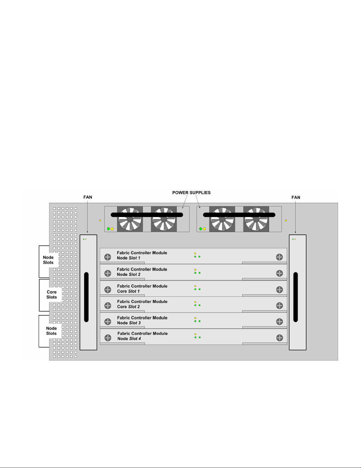
Diagram of the Chassis
Figure 1-1: Front Chassis View without Bezel

14
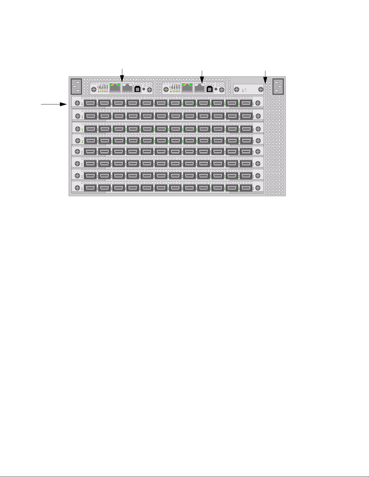
Figure 1-2: Back Chassis View
15
Chassis Slot Numbering
Slot numbers are printed on the chassis for easy identification.
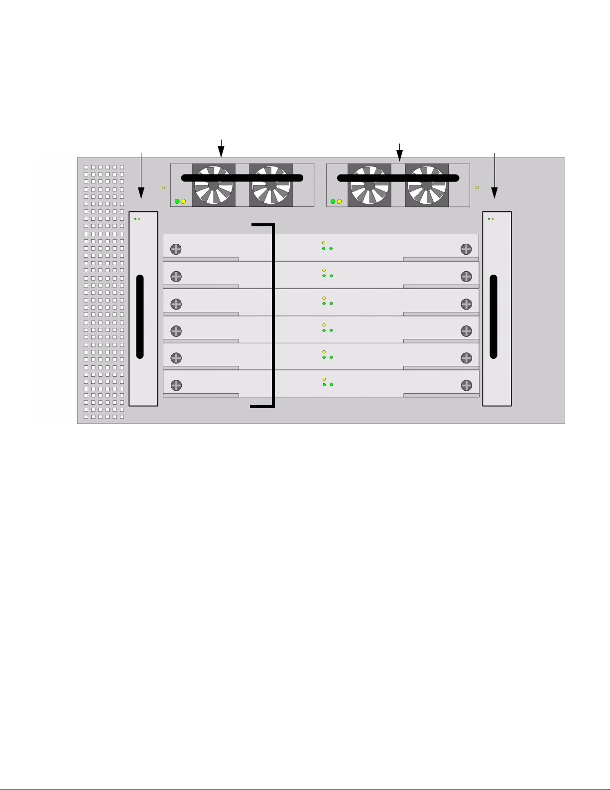
Figure 1-3: Chassis Slot Numbering in Front (Non-port Side)
Power Supply ID 1
Power Supply ID 2
Fan ID 2
Slot # 9
Slot # 10
Slot # 11
Slot # 12
Slot # 13
Slot # 14
Fan ID 1
16
Figure 1-4: Chassis Slot Numbering in Back (Service Side)
Dimensions
• Height: 6U unit
• Width: 17.04”
• Depth: 8” - 23.7”
• Wei ght: maximum 106 pounds (full chassis configuration with 4x copper Line Interface Modules)
Connections
• 96 ports of 10 Gbps 4X Copper InfiniBand.
• Two 10/100 Ethernet RJ-45 Management-Ethernet ports for out-of-band management.
• Two RJ-45 Console Port used to configure and monitor the Topspin 270/Cisco SFS 7008.
• Rack Alarm.
All cabling is on the rear of the chassis.
LEDs
LEDs are located on both the front and back of the chassis. Refer to “Interpreting the Front Panel
LEDs” on page 67 and “Interpreting the Back Panel LEDs” on page 73 for more information.
Power Supplies
Refer to “Installing a New Power Supply Module” on page 38 for installation instructions.
The Topspin 270/Cisco SFS 7008 has two AC-DC bulk power supply modules.
• Only one power supply, in either of the two slots, is required to power the system. However, a
blanking panel is required for any unused bay.
Slot # 15
Slot # 16
Slot # 17
Slot # 1
Slot # 2
Slot # 3
Slot # 4
Slot # 5
Slot # 6
Slot # 7
Slot # 8
17
• The power supplies are 1U, 48V, 1200W
• The supplies provide regulated +48V DC to all other modules in the system.
• Each power supply has self contained fans for cooling.
Fan Trays
Refer to “Installing a Fan Module” on page 41 for installation instructions.
The fan trays are redundant, hot-swappable cooling units.
• Only one fan tray, in either of the two slots, is required to cool the system. However, a blanking
panel is required for any unused bay.
• The replacement of any one fan tray does not disrupt the operation of the device in any way, and
can be successfully completed without having to remove the device from a rack, or disconnect any
cables.
• The fan modules use DC Voltage regulators to control fan speed and contain a hardware fan control
circuit, which controls and monitors the fan speed.
• The fan module will default to full speed after a power-on or reset condition.
• If one the fans fails, the redundant fan will go to full speed (if one is available).
CAUTION: The fan modules do not have guards. Do not remove a fan module completely from the
bay until the blades have stopped moving (approximately 15 seconds).
Management Interface Modules
See Figure 1-2 on page 14 for a diagram of the chassis.
Refer to “Installing a Management Interface Module” on page 50 for installation instructions.
The Topspin 270/Cisco SFS 7008 supports redundant, hot-swappable Management Interface modules,
each of which is paired to one of the Fabric Controller Core modules.
The Management Interface modules provide the following functions:
• RS-232 serial console port
• 10/100 Ethernet management port
• System real time clock (RTC)
• Intra-system Ethernet switch, which provides a system configuration management data-path to all
fabric modules.
• Provide mirrors of the LED indicators from the front side of the chassis for the power supply, fans,
and over-all system status. (refer to “Management Interface Module LEDs” on page 73).
• Rack Alarm Connection (refer to “Rack Alarm” on page 19).
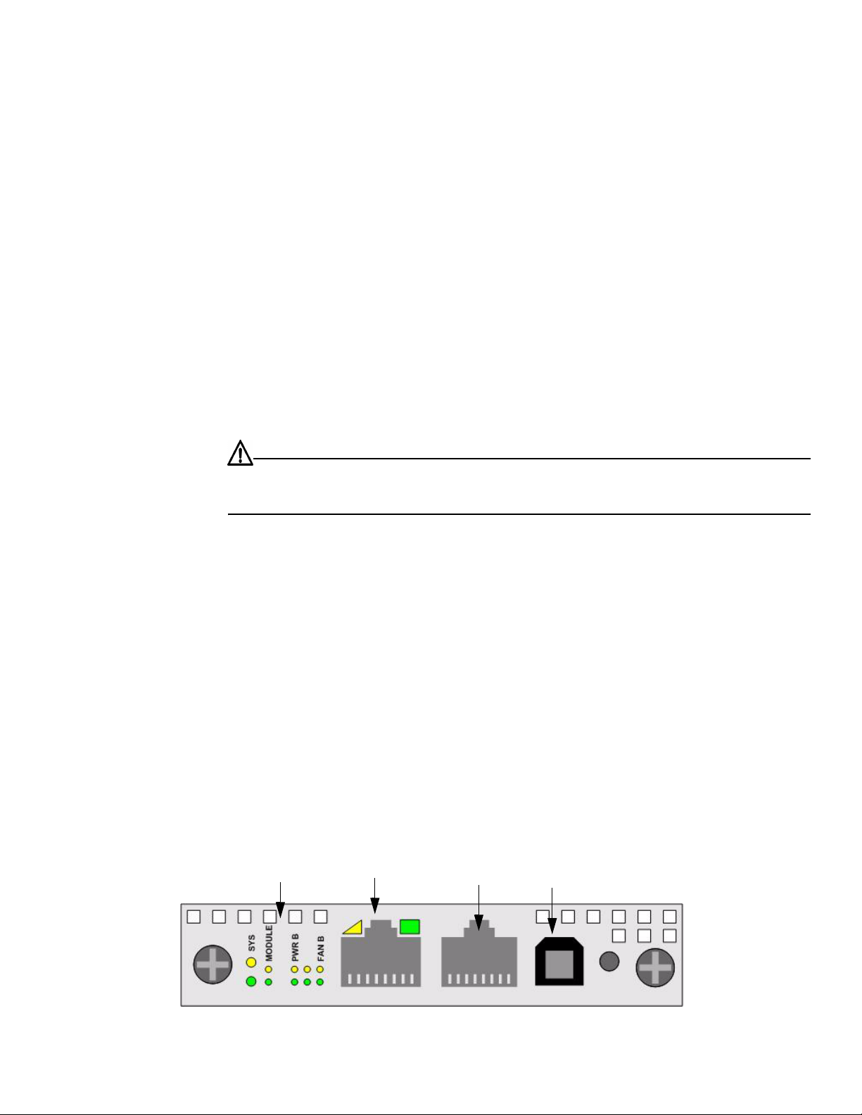
Figure 1-5: Management Interface Module
Rack Alarm
Ethernet
Port
Serial
Port
Redundant
LEDs

18
Understanding the Core Slot to Mgmt Interface Module Connection
Each Core slot in the chassis (refer to “The Core Slot” on page 18) is connected to 1 port on the
Management Interface module. The controller (fabric interface module inserted in the core slot) selects
the Management Interface module to which it will connect.
The pairing of Management Interface module to core slot is as follows:
• The Management Interface module in slot #15 is connected to the Fabric Controller Module in the
Core slot #11.
• The Management Interface module in slot #16 is connected to the Fabric Controller Module in the
Core slot #12.
For example, removing the Fabric Controller from the Core slot 11 would cause both the Fabric
Controller card and its paired Management Interface module in slot 15 to fail-over. The new primary
Controller would be slot 12 and the primary Management Interface would be slot 16.
Fabric Controller Modules
See Figure 1-2 on page 14 for a diagram of the chassis.
Refer to “Installing a Fabric Controller” on page 44 for Fabric Controller module installation
instructions.
The Topspin 270/Cisco SFS 7008 contains six fabric control modules.
The fabric controller modules perform the following roles within the system:
• System Controller
• Switch fabric spine
• Switch fabric end-nodes
• Stores redundant Vital Product Data (VPD) from the Chassis ID module. This allows the chassis to
continue functioning (and the VPD information to be recovered) even if a Chassis ID module fails.
Each Fabric Controller module runs the management software and contains non-volatile storage.
The behavior and responsibility of each fabric controller module is determined by the type of slot into
which it is inserted. Each fabric controller module can be installed in either a Node slot or a Core slot
(refer to “Node and Core Slots” on page 18).
Master/Slave and Standby Roles
When the CPU of a fabric module detects that is in a Core slot, it will arbitrate for system mastership
and run system wide control functions in addition to its local management functions.
• One fabric controller in the Core slot acts as the Master
• One fabric controller in the Core slot acts as the Standby to the Master
• Fabric controllers in Node slots act as slaves
• Note: Fabric controllers in Node slots do not act in active/standby configuration
Node and Core Slots
The fabric controller modules can occupy either a Node slot or a Core slot in the chassis.
The Node Slot
There are four Node slots in the Topspin 270/Cisco SFS 7008.
Fabric modules installed in Node slots provide fabric leaf switching, as opposed to controller
functionality.
The Core Slot
There are two Core slots in the Topspin 270/Cisco SFS 7008.
19
• At least one Fabric Controller module must be installed in the Core slot for the chassis to boot.
• When a module is installed in a Core slot, it acts as either the master or standby controller for the
chassis, with all modules in the system being slaves to the master controller.
• The subnet manager runs on the fabric module installed in the Core slot that has arbitrated to be the
master.
• The Core slot module also acts as the switch fabric spine, interconnecting the end-nodes.
Each Core slot is connected to 1 of 2 ports on the Management Interface module.
The pairing of core slot to Management I/O module is as follows:
• The Fabric Interface Module in the Core slot #11 is connected to the Management I/O module in
slot #15 .
• The Fabric Interface Module in the Core slot #12 is connected to the Management I/O module in
slot #16.
Line Interface Modules (LIM)
Refer to “Installing a LIM Module” on page 48 for installation instructions.
The Topspin 270/Cisco SFS 7008 has hot-swappable Line Interface Modules (LIMs), which are
installed in the rear of the chassis; this is opposite of the fabric modules (see Figure 1-2 on page 14).
The LIMs provide the physical InfiniBand port interfaces and are 4x over copper. The number of LIMs
in your Topspin 270/Cisco SFS 7008 chassis depends on your particular configuration.
Chassis ID Module
The chassis ID module is hot-swappable, and is located on the rear of the chassis (see Figure 1-2 on
page 14).
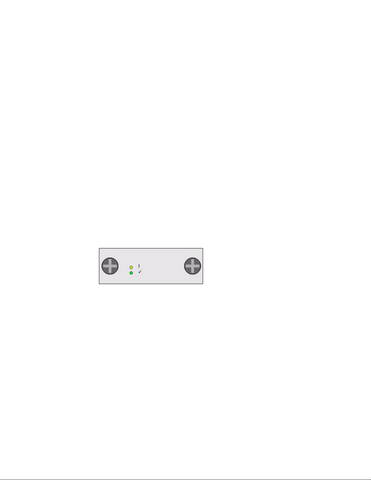
Figure 1-6: Chassis ID Module
How the Chassis ID is Used
Upon initial boot-up of the Topspin 270/Cisco SFS 7008, the Chassis ID is read by the system, and the
unique information is populated to the rest of the chassis.
The Chassis ID module contains model and serial number information, and logs certain error
information. Refer to “Vital Product Data Storage” on page 20.
About Replacing a Chassis ID Module
In the event that a Chassis ID module must be replaced, the replacement module will arrive with your
previous serial number and GUID. When a Chassis ID modules is installed, the new Chassis ID is
detected. This allows your chassis to maintain the same identification and GUID.
Rack Alarm
The Rack Alarm (also referred to as the Rack Locator) feature is supported with release 2.3.0 and later.

20
Administrative Features
Real-Time Clock
The Topspin 270/Cisco SFS 7008 maintains correct time regardless of power conditions or
connectivity.
Latency
The Topspin 270/Cisco SFS 7008 has port to port latency of less than 600ns.
Non-Volatile Memory
The memory supports up to:
• three stored system images (not including recovery image)
• one week of log files at normal verbosity; and one day of log files at maximum verbosity
Vital Product Data Storage
Vital Product Data (VPD) is stored in non-volatile memory in the Chassis ID module (refer to “Chassis
ID Module” on page 19) and the Fabric Controller that is installed in the Core slot (refer to “Fabric
Controller Modules” on page 18), and is available electronically. Some VPD info can be accessed via
CLI, the Java GUI, or the Web GUI.
The following Vital Product Data can be recovered by returning a Field Replaceable Unit to the original
manufacturer. Note: This requires the appropriate support contract.
• Power on hours
• Manufacturing part number
• Serial number
• Final test date
•Card ID
• Failure code
• Failure date
• Operation status
•Failure log
• OEM part number
Diagnostics
Refer to “About Diagnostic Tests” on page 91 for more detailed information.
The following tests are run to determine operational status:
• Power On Self Test (POST) is performed on all system components during power on to determine
operational readiness.
• Redundant components' operational status is ensured periodically during normal operation,
including the logic required to perform the transition from faulted/primary to redundant
component. Detection of abnormal status is reported.

21
2
Installing the Topspin 270/Cisco SFS 7008
This chapter describes how to install and manage the Topspin 270/Cisco SFS 7008 system hardware.
• “Prepare the Site” on page 21
• “Configure Basic Connectivity” on page 29
• “Mount the Topspin 270/Cisco SFS 7008 Chassis in a Rack” on page 22
• “Connect Network Devices” on page 30
• “Manage the System” on page 31
Prepare the Site
This section provides information that you need to safely and successfully prepare your environment for
your Topspin 270/Cisco SFS 7008. Read this section carefully before you install your device.
Read the Cautionary Statements
Refer to the “FCC Statement” on page vii and the “Safety Information” on page vii.
Prepare the Physical Environment for the
Topspin 270/Cisco SFS 7008 System
• Make sure you have the right cables and sufficient ventilation.
• Unpack the Topspin 270/Cisco SFS 7008 package.

22
• Prepare a management workstation, such as a PC running a terminal program, and a
straight-through M/F DB-9 serial cable (included).
Mount the Topspin 270/Cisco SFS 7008 Chassis in a
Rack
This section describes how to install the Topspin 270/Cisco SFS 7008 chassis in an equipment rack. The
following procedure is the standard installation, using your own rack shelf.
Topspin also has an optional shelf that is appropriate for pre-racking and shipping a unit in the rack. If
you have purchased this shelf unit separately, refer to the documentation that is provided in the shelf kit
package.
Requirements
In addition to the accessories provided with the server switch, you should have:
• #2 phillips screwdriver
• Rack with 6Us of available space
• Shelf installed in the rack (not provided). The shelf must support the weight of the chassis, which
can be up to 106 pounds with all possible components installed.
• Screws appropriate to your rack, which are used to secure the rack handles to the rack posts.
• Three people are recommended to lift the switch into the rack; however, the procedure can be
performed by two people.
NOTE: The Topspin 270/Cisco SFS 7008 chassis weighs up to 106 pounds (fully loaded).
Rack Mount Installation
To mount the Topspin 270/Cisco SFS 7008 chassis in a rack:
1. Remove the CD-ROM, parts bag, and documentation from the box.
2. Remove the packaging from around the chassis.
23
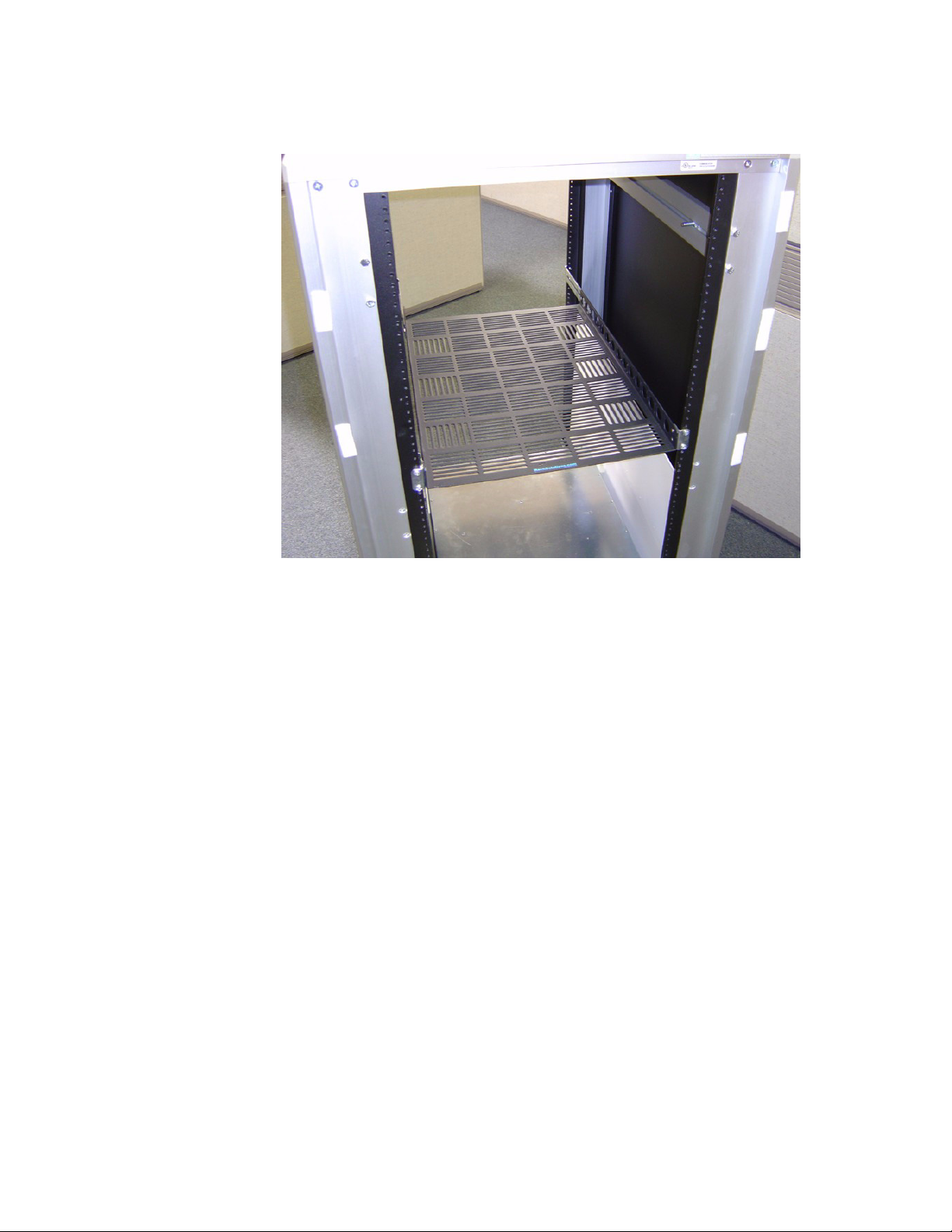
3. Install a shelf for the chassis, if you have not already done so. Verify that the shelf can support the
weight of the chassis, which can be up to 106 pounds with all possible components installed.
Figure 2-1: Install Appropriate Rack in Shelf
4. Determine the direction that the switch will be installed and justified in the rack. The direction that
the switch will be justified will determine which set of rack ears that need to be removed.
5. Use a #2 phillips screwdriver to remove one set of rack ears:
• If you have determined that the switch will be justified toward the front of the rack, then use a
#2 phillips screwdriver to unscrew the rack ears from the back of the switch.
24
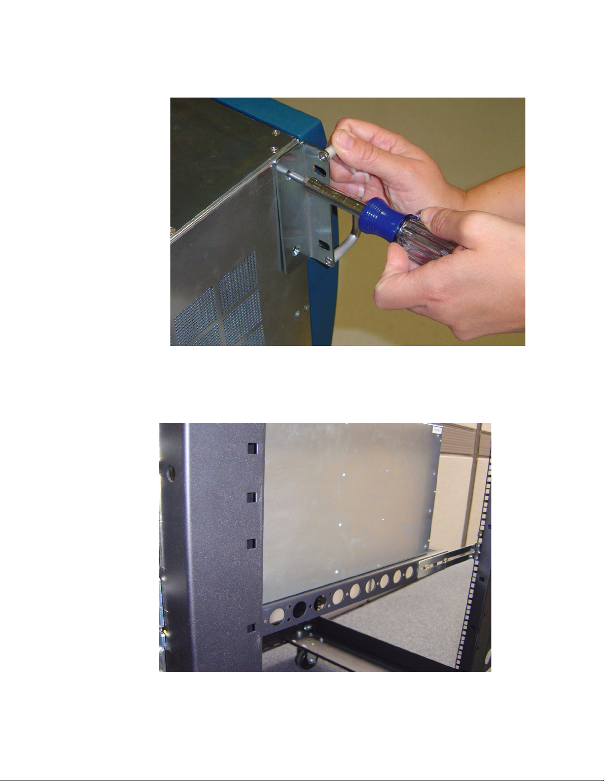
• If you have determined that the switch will be justified toward the back of the rack, then use a
#2 phillips screwdriver to unscrew the rack ears from the front of the switch.
Figure 2-2: Unscrew Extra Rack Ears from the Chassis
6. Separate the rack ears from the chassis when all screws have been loosened.
7. Use 2 - 3 people to lift the switch into the rack.
Figure 2-3: Chassis Set onto Shelf
25
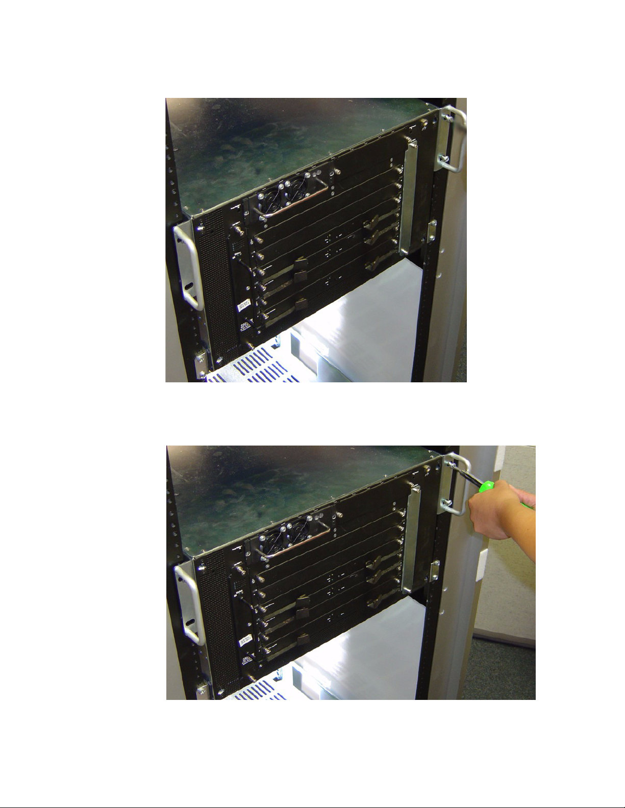
8. Push the chassis into the rack until the rack ears are flush with rails.
Figure 2-4: Rack Ears Flush with Rails
9. Use screws that fit your rack to attach both rack ears to the rack rails.
Figure 2-5: Use Appropriate Screws to Attach Rack Ears to Rails

26
Install Optional HA Components
If you have purchased a High-Availability (HA) package, install the following components:
• Redundant Power Supply. Refer to “Power Supply Modules” on page 35.
• Redundant Fan Tray. Refer to “Fan Tray Modules” on page 39.
• Redundant Management Interface Module. Refer to “Management Interface Modules” on page 49.
Connect Management Devices
To connect the management ports, use either a serial cable and/or an Ethernet cable.
Figure 2-6: Serial and Ethernet Management Ports
Attach a Serial Console Cable to a PC or
Terminal
1. Attach the RJ-45 console cables from the cable kit that is provided. See Figure 2-7.
a. Connect the cables to the InfiniBand chassis serial console port on the Management Interface
card.
If you have two Management Interface cards, make sure that you connect to the left Management
Interface module (slot 15), which will be the primary Management card upon initial boot-up. The
serial console port is labeled “10101.”
b. Connect the other end of the serial cable to your terminal server or management workstation.
For detailed information on how to connect the serial console cable, please see the
documentation included with the serial cable kit.
2. Open a terminal emulation window using a program such as HyperTerminal for Windows. Set your
terminal parameters to the following:
27
•Baud: 9600 bps
• Data Bits: 8
• Parity: None
• Stop Bits: 1
• Flow control: None
Connect an Ethernet Cable to the Ethernet
Management Port
3. Connect an Ethernet cable to the Ethernet port of the left Management Interface module (slot
number 15). See Figure 2-7.
a. If you have two Management Interface modules, you may also want to connect an Ethernet
cable to the standby module (slot 16) to maintain Ethernet connectivity in the event of a
fail-over.
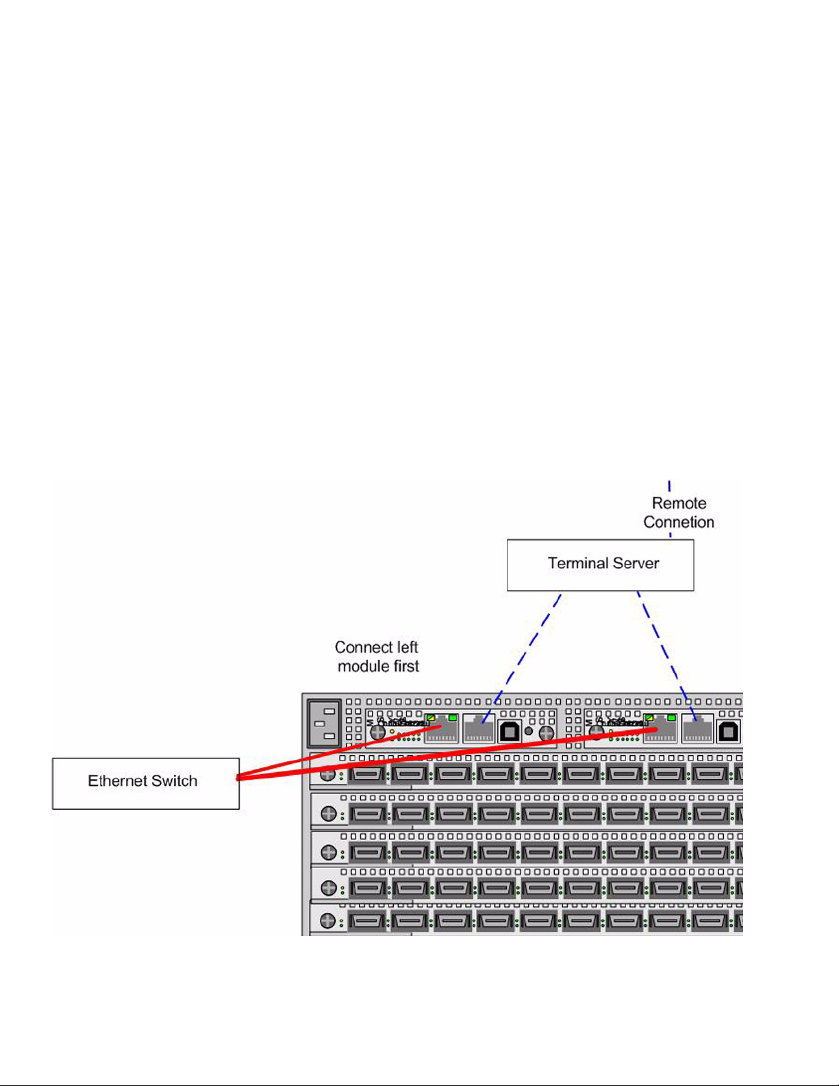
Recommended Management Configuration
The diagram below shows the recommended management port connections. To have constant access to
the chassis remotely, redundantly connect the serial ports on two Management Interface cards to a
terminal server.
Figure 2-7: Recommended Management Configuration
28
Power on the Chassis
Use only the power cable provided with your InfiniBand system.
4. Remove the power cords from the shipping package.
One power cord UL rated 12 Amps/125 VAC or greater is provided by default. If you have a
high-availability unit, you will have a second power cord.
5. Inspect the power cord and determine if it provides the proper plug and is appropriately certified for
use with your electrical system. Discard the cord if it is inappropriate for your national electrical
system and obtain the proper cord, as required by your national electrical codes or ordinances.
Grounding is supplied by the ground-prong on the 3-prong power plug. Do not attach a separate
ground cable. Do not use adapter plugs. Do not remove the ground prong from the cable. Ensure
the ground connection on the power supply is correct and functioning before applying power to the
chassis.
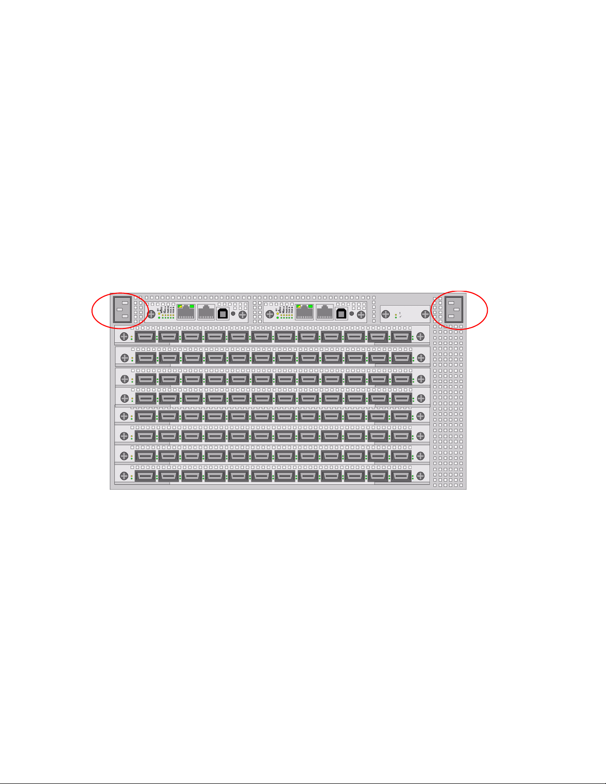
6. Insert the power cords to the power jacks on the rear of the chassis. If you only have a single power
cord, insert it into the left receptacle.
Refer toFigure 2-8 for power jack locations.
Figure 2-8: Power Jack Locations
7. Plug the other end of each AC power cable into a 90-264VAC power outlet operating at 47-63Hz.
Attach the chassis only to approved power sources, as indicated by the electrical ratings label. If
you are unsure of the correct power-source to use, contact your support personnel or your local
power company.
The chassis automatically starts and boots. You can watch the running status via the serial console.
Use the correct external power-source.
8. Check the LEDs on the front of the Topspin 270/Cisco SFS 7008 system. When the system first
powers up, it performs a power-on self test (POST). Refer to “System-Wide Status LED” on
page 68.
You will know that the system has completed the boot process when you see a login prompt.

29
Configure Basic Connectivity
1. Configure an IP address for the Ethernet Management port.
It is necessary to configure connectivity to the out-of-box Ethernet management port in order to use
Telnet, the Web GUI, or the Java GUI. The system is not pre-configured when it ships from the
factory.
IP addresses can be assigned statically (which is the default), or dynamically assigned using DHCP.
• “Assigning an Address Statically” on page 29
• “Assigning an Address Dynamically” on page 30
Assigning an Address Statically
Refer to the static example below:
a. When the system has completed booting, press <Enter> several times to display the CLI
prompt.
b. Enter the user name and password. The default user name is super, and the default password is
super.
c. Enter the enable command.
d. Enter the configure command.
e. Enter the interface mgmt-ethernet command.
f. Enter the IP address of the management port followed by the netmask.
g. Set the default gateway for the management port. For example:
h. Enable the management port by entering the no shutdown command.
i. Save the configuration to preserve it between reboots.
Login:
Login: super
Password: super
SFS-270>
SFS-270> enable
SFS-270#
SFS-270# configure
SFS-270(config)#
SFS-270(config)# interface mgmt-ethernet
SFS-270(config-if-mgmt-ethernet)# ip address 10.10.0.22
255.255.255.0
SFS-270(config-if-mgmt-ethernet)# gateway 10.10.0.1
SFS-270(config-if-mgmt-ethernet)# no shutdown
SFS-270(config-if-mgmt-ethernet)# exit
SFS-270(config)# exit
SFS-270# copy running-config startup-config

30
Assigning an Address Dynamically
a. When the system has completed booting, press <Enter> several times to display the CLI
prompt.
b. Enter the user name and password. The default user name is super, and the default password is
super.
c. Enter the enable command.
d. Enter the configure command.
e. Enter the interface mgmt-ethernet command.
f. Enter the option dhcp command. The chosen method will be persistent across module reboots.
g. Enable the management port by entering the no shutdown command.
h. Save the configuration to preserve it between reboots.
If you have two Fabric Controllers installed in Core slots, you will receive a message asking if you
want to save the configuration to the Standby Controller.
i. Answer Ye s to save the configuration across both controllers.
Connect Network Devices
This section describes how to connect the InfiniBand system to other network devices. InfiniBand
devices can be connected to InfiniBand-enabled servers.
About Connectors
The Topspin 270/Cisco SFS 7008 device supports the following types of connectors:
• Management ports:
• Serial console port: male DB-9 connector.
• Ethernet Management port: RJ-45 jack for unshielded twisted-pair connections.
• Switch card: 4X 10 Gbps InfiniBand connectors.
Login:
Login: super
Password: super
SFS-270>
SFS-270> enable
SFS-270#
SFS-270# configure
SFS-270(config)#
SFS-270(config)# interface mgmt-ethernet
SFS-270(config-if-mgmt-ethernet)# option dhcp
SFS-270(config-if-mgmt-ethernet)# no shutdown
SFS-270(config-if-mgmt-ethernet)# exit
SFS-270(config)# exit
SFS-270# copy running-config startup-config
Loading...